
In mechanical power transmission, the design of spur and pinion gear pairs is foundational. Traditional design methodologies, which rely on standardized rack cutters, offer simplicity and interchangeability. However, they inherently constrain the performance potential of the gear set to a predefined, limited subset of possible geometries. To overcome this limitation and achieve truly optimized performance for specific operational conditions, the Direct Gear Design approach is employed. This method liberates the designer from the predefined tool constraints, allowing for the independent synthesis of gear tooth profiles to meet precise functional requirements. This article details a comprehensive direct design methodology for involute spur and pinion gear sets, centering on the construction and utilization of an “Area of Existence” for selecting optimal working profile parameters, followed by an analytical selection of the optimal root fillet contour.
The core of the direct design for the involute working profile lies in treating the gear tooth not as a product of a standard tool, but as a geometric entity defined by its fundamental circles. A spur gear tooth profile comprises two involute flanks originating from the base circle $d_b$, the tip circle $d_a$, the root circle $d_f$, and the root fillet transition. Key formative parameters are defined not by a tool, but directly by the designer. The pressure angle at the point where the two involute flanks would intersect, often termed the involute tip point or the point of sharpening, is a primary variable:
$$ \nu = \arccos\left(\frac{d_b}{d_\triangle}\right) $$
where $d_\triangle$ is the diameter of the sharp tip circle. The pressure angle at the tip circle is:
$$ \alpha_a = \arccos\left(\frac{d_b}{d_a}\right) $$
To control tooth thickness at critical diameters, the base circle thickness coefficient $m_b$ and the tip circle thickness coefficient $m_a$ are introduced. Their definitions are fundamental to direct design:
$$ m_b = \frac{s_b}{p_b} = \frac{2 r_b \text{inv}(\nu)}{d_b \pi / z} = \frac{z \,\text{inv}(\nu)}{\pi} $$
$$ m_a = \frac{s_a}{p_b} = \frac{z \,[\text{inv}(\nu) – \text{inv}(\alpha_a)]}{\pi \cos \alpha_a} $$
Here, $s_b$ is the base circle tooth thickness, $s_a$ is the tip circle tooth thickness, $p_b$ is the base pitch, $r_b$ is the base radius, and $z$ is the number of teeth. The tip thickness coefficient $m_a$ is typically chosen within a recommended range (e.g., 0.1 to 0.5) to prevent an excessively sharp tooth tip while ensuring adequate contact ratio.
For a mating spur and pinion gear pair, the condition for backlash-free meshing at the operating center distance $a_w$ must be satisfied. This condition, along with the geometry of involute curves, links the parameters of the two gears. The sum of the tooth thicknesses on the operating pitch circles must equal the operating circular pitch:
$$ s_{w1} + s_{w2} = p_w $$
$$ p_w = \frac{\pi d_{w1}}{z_1} = \frac{\pi d_{w2}}{z_2} $$
$$ s_{w1} = [\text{inv}(\nu_1) – \text{inv}(\alpha_w)] \frac{d_{b1}}{\cos \alpha_w} $$
$$ s_{w2} = [\text{inv}(\nu_2) – \text{inv}(\alpha_w)] \frac{d_{b2}}{\cos \alpha_w} $$
where $d_{w1}, d_{w2}$ are operating pitch diameters, $d_{b1}, d_{b2}$ are base diameters, and $\alpha_w$ is the operating pressure angle (mesh angle). The center distance is given by:
$$ a_w = \frac{d_{b1}(1+u)}{2 \cos \alpha_w} \quad \text{or equivalently} \quad d_{b1} = \frac{2 a_w \cos \alpha_w}{1+u} $$
where $u = z_2 / z_1$ is the gear ratio. It is also crucial to ensure the active part of the involute begins outside the root circle to avoid undercutting. The pressure angle at the start of the active profile (form circle) for each gear is:
$$ \alpha_{p1} = \arctan\left[ (1+u)\tan\alpha_w – u \tan\alpha_{a2} \right] $$
$$ \alpha_{p2} = \arctan\left[ \frac{(1+u)\tan\alpha_w – \tan\alpha_{a1}}{u} \right] $$
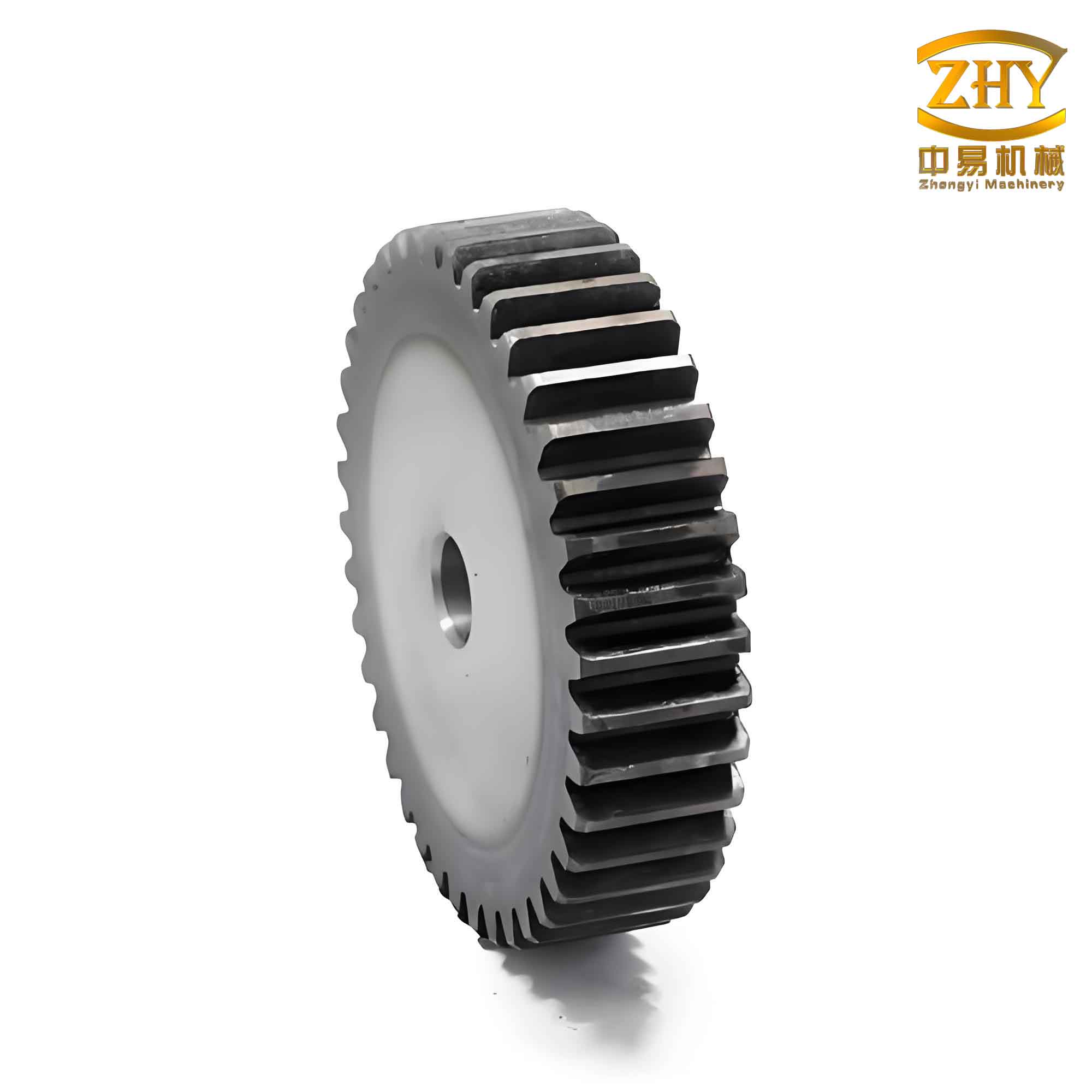
The most powerful tool in the direct design of a spur and pinion gear set is the concept of the Area of Existence. This is a two-dimensional domain that maps all geometrically feasible and functionally acceptable combinations of the primary tooth profile variables for a given set of constraints. For a pair of gears with specified tooth numbers $z_1$, $z_2$, and chosen tip thickness coefficients $m_{a1}$, $m_{a2}$, the axes of this domain can be the pressure angles at the sharp tip points $\nu_1$ and $\nu_2$, or equivalently, the tip pressure angles $\alpha_{a1}$ and $\alpha_{a2}$. The boundaries of this area are defined by curves representing critical performance criteria, plotted as contour lines (isograms).
The equations for these key performance contours are derived from the fundamental relations of involute gearing. The contour for a constant operating pressure angle $\alpha_w$ is given by:
$$ \text{inv}(\alpha_w) = \frac{\text{inv}(\nu_1) + u \cdot \text{inv}(\nu_2) – \pi / z_1}{1 + u} $$
The contour for a constant transverse contact ratio $\varepsilon_\alpha$ is:
$$ \varepsilon_\alpha = \frac{z_1 [ \tan\alpha_{a1} + u \tan\alpha_{a2} – (1+u) \tan\alpha_w ]}{2\pi} $$
To prevent undercutting (interference at the root), the start-of-active-profile pressure angle must be greater than zero. This yields the interference boundary lines:
$$ \alpha_{p1}=0: \quad (1+u)\tan\alpha_w – u \tan\alpha_{a2} = 0 $$
$$ \alpha_{p2}=0: \quad (1+u)\tan\alpha_w – \tan\alpha_{a1} = 0 $$
The condition where the pitch point $P$ coincides with the endpoints of the path of contact defines the boundary between different regimes of mesh. These node position contours are:
$$ \alpha_{a1} = \alpha_w: \quad \text{inv}(\nu_1) – \text{inv}(\alpha_w) = \pi m_{a1} \cos\alpha_{a1} / z_1 $$
$$ \alpha_{a2} = \alpha_w: \quad \text{inv}(\nu_2) – \text{inv}(\alpha_w) = \pi m_{a2} \cos\alpha_{a2} / z_2 $$
Furthermore, an important criterion for wear performance is the specific sliding. The contour for equal specific sliding at the mesh entry and exit ($\eta_1 = \eta_2$) is:
$$ \tan\alpha_{a1} – u \tan\alpha_{a2} + (u-1) \tan\alpha_w = 0 $$
By plotting these contours on the $\nu_1$-$\nu_2$ (or $\alpha_{a1}$-$\alpha_{a2}$) plane, the Area of Existence emerges. For a functional spur and pinion gear pair, the transverse contact ratio must be greater than 1. Therefore, the practical existence domain is bounded by the $\varepsilon_\alpha = 1.0$ contour and the two interference contours $\alpha_{p1}=0$ and $\alpha_{p2}=0$. Every point within this closed domain represents a valid, unique set of geometric parameters for the spur and pinion gear pair. This visualization allows the designer to directly select a point that best satisfies a weighted combination of performance targets—for instance, maximizing contact ratio, achieving a desired pressure angle, or balancing specific sliding—thereby enabling true performance-driven optimization.
| Point | $\nu_1$ (°) | $\nu_2$ (°) | $\alpha_w$ (°) | $\varepsilon_\alpha$ | Characteristics |
|---|---|---|---|---|---|
| A | 37.76 | 34.51 | 29.80 | 1.02 | On $\varepsilon_\alpha=1.0$ boundary; minimum contact ratio, maximum mesh angle. |
| B | 30.33 | 34.19 | 25.37 | 1.21 | $\alpha_{a1} < \alpha_w$, node outside path of contact. |
| C | 38.13 | 25.41 | 21.11 | 1.16 | $\alpha_{a2} < \alpha_w$, node outside path of contact. |
| D | 35.12 | 23.46 | 12.37 | 2.15 | Intersection of $\alpha_{p1}=0$ and $\alpha_{p2}=0$; maximum contact ratio, minimum mesh angle, both gears at undercutting limit. |
| E | 34.51 | 29.82 | 22.26 | 1.46 | Central point within the domain; balanced performance. |
After optimizing the working involute profile via selection from the Area of Existence, the design of the non-active root fillet must be addressed. The fillet has a significant impact on bending stress concentration and thus the fatigue life of the spur and pinion gear. In direct design, the fillet is not tied to a standard tool tip but can be synthesized independently. Common smooth transition curves include single arc, double arc, parabolic, and elliptical profiles.
The geometry of the fillet generated by a rack-type cutter with a given tip profile can be derived using the theory of gearing. Consider generating the pinion (gear 1) with a rack cutter. Multiple coordinate systems are established: a fixed system $S_f(O_f-X_fY_f)$, a moving system $S_2(O_2-X_2Y_2)$ attached to the translating rack, and a moving system $S_1(O_1-X_1Y_1)$ attached to the rotating gear. The rack translates a distance $r_{w1}\phi$ for a gear rotation of $\phi$. The condition of contact (meshing) between the rack tip curve and the generated gear fillet provides the relation $\phi = (x – y \cot t)/r_{w1}$, where $(x, y)$ are the coordinates of a point on the rack tip in $S_2$, and $t$ is a parameter related to the normal direction.
For a single circular arc tip on the rack with radius $r_f$, its parametric equation in $S_2$ is:
$$ \begin{cases} x = r_f \cos t \\ y = r_f \sin t – h_{r1} + r_f \sin \alpha_w \end{cases}, \quad t \in [\pi+\alpha_w, 2\pi-\alpha_w] $$
where $h_{r1}$ is the rack addendum. The coordinates of the corresponding generated fillet point in the gear coordinate system $S_1$ are obtained via coordinate transformation:
$$ \begin{aligned} x_1 &= x \cos \phi + y \sin \phi + r_{w1}(\sin \phi – \phi \cos \phi) \\ y_1 &= -x \sin \phi + y \cos \phi + r_{w1}(\cos \phi + \phi \sin \phi) \end{aligned} $$
Similar derivations can be performed for double circular arc, parabolic, and elliptical rack tip profiles to obtain their respective generated fillet equations.
To select the optimal fillet, a comparative stress analysis is essential. Three-dimensional finite element models of the spur and pinion gear pair are constructed for each fillet type, using identical working profile parameters (e.g., from point E in the existence domain). A torque $T$ is applied to the driving gear, and the maximum bending stress at the root fillet of both gears is extracted. The goal is to minimize this peak stress.
| Root Fillet Profile Type | Max Bending Stress – Pinion (MPa) | Max Bending Stress – Gear (MPa) | Relative Performance |
|---|---|---|---|
| Single Circular Arc | 266.0 | 144.4 | Lowest stress for both members. |
| Double Circular Arc | 279.5 | 166.3 | Higher stress concentration. |
| Parabolic | 267.0 | 147.0 | Close to single arc, slightly higher. |
| Elliptical | 267.4 | 146.9 | Close to single arc, slightly higher. |
The results from such an analysis, as tabulated above for an illustrative case, clearly indicate which fillet profile provides the most favorable stress state. In this specific instance, the single circular arc profile yielded the lowest maximum bending stress for both the spur and pinion gear, establishing it as the optimal choice. This selection, combined with the previously optimized involute parameters, completes the direct design of a high-performance, application-tailored gear set.
In conclusion, the direct design methodology for involute spur and pinion gear sets, centered on the Area of Existence, provides a powerful and systematic framework for performance-driven gear synthesis. By mapping all feasible combinations of primary tooth parameters against key performance contours like contact ratio, mesh angle, and interference limits, designers can visually and analytically select the optimal working profile geometry for their specific needs, moving beyond the restrictions of standardized tooling. Subsequently, the root fillet can be independently designed and optimized through comparative stress analysis of various smooth transition curves, such as single arc, double arc, parabolic, and elliptical forms, to minimize bending stress concentration. This two-stage process—first optimizing the active involute flank via the existence domain, and then optimizing the root fillet via stress analysis—ensures that the final spur and pinion gear design is not just feasible, but truly optimal for its intended load, life, and efficiency requirements. The method empowers engineers to fully exploit the geometric potential of the involute for advanced mechanical transmissions.