
As a design engineer specializing in mechanical transmission systems, I have extensive experience in using UGNX for parametric solid modeling of complex gear profiles. UGNX, originally developed by EDS, is a powerful integrated CAD/CAE/CAM platform that excels in parametric and feature-based design. Its ability to combine parametric modeling with feature-based thinking allows me to define features using dimensional driving or variable design methods. In particular, UGNX offers unmatched capabilities for complex surface modeling and freeform shape creation, which are essential for designing worm gears. Worm gear drives are widely used in machine tools, automotive systems, instruments, hoisting machinery, metallurgical equipment, and other machinery due to their compact structure, large transmission ratio, smooth operation, and reliable self‑locking under certain conditions. However, the complex tooth profile of worm gears makes it difficult to directly create three‑dimensional solid models using conventional CAD/CAM software. Through UGNX’s tools such as “Law Curve”, “Expression”, and “Dynamic WCS”, I can construct intricate tooth curves. Nevertheless, for designers unfamiliar with UG, the learning curve is steeper compared to other CAD software. In this article, I will describe my parametric modeling process for an Archimedean worm gear pair, which serves as a reference for modeling other complex 3D parametric shapes.
Geometric Characteristics of Worm Gears
Worm and worm gear drives evolved from crossed‑axis helical cylindrical gears. Each tooth of the worm can wrap around the pitch cylinder more than one full turn, giving the worm a screw‑like appearance. To improve meshing, the pitch cylinder of the worm gear is typically curved into a circular arc so that it partially envelops the worm. The worm gear is usually generated by a hob that has the same shape and parameters as the worm, resulting in line contact between tooth surfaces and enabling the transmission of larger power. Thus, the worm drive shares some characteristics with screw drives: the worm acts as a screw, and the worm gear acts as a nut that partially encloses the worm. The worm belongs to the shaft‑type part family; its basic geometric structure consists of different shaft sections with features such as teeth, keyways, chamfers, and undercuts. The worm gear belongs to the disc‑type part family; its main body is a revolved solid with teeth, holes, ribs, keyways, and other features.
Parameter Table for the Worm
For my Archimedean worm example, the key parameters are listed in the table below. These parameters define the geometry of the worm and are used throughout the modeling process.
| Parameter | Symbol | Value | Unit |
|---|---|---|---|
| Axial module | \(m_{ax}\) | 2 | mm |
| Number of worm starts | \(z_1\) | 1 | – |
| Pressure angle | \(\alpha\) | 20° | deg |
| Lead angle | \(\gamma\) | 4°23’55” | deg |
| Pitch circle diameter | \(d_1\) | 26 | mm |
| Addendum circle diameter | \(d_{a1}\) | 30 | mm |
| Dedendum circle diameter | \(d_{f1}\) | 21 | mm |
Modeling Process of the Worm
Creating the Worm Blank
I start by creating the worm blank, which is a revolved body. Using the UG Sketch functionality, I draw the cross‑section shown below. The sketch is fully dimensioned in a parametric manner, so that any subsequent modification to the sketch dimensions automatically updates the solid body. After completing the sketch, I use the “Revolve” command to create the main cylindrical shape, followed by “Chamfer” to add the necessary bevels. The resulting worm blank is illustrated in the following solid model representation.
Creating the Tooth Space Profile
To generate the helical tooth space, I first adjust the working coordinate system (WCS) using the “Dynamic WCS” command so that the ZC axis aligns with the lead angle \(\gamma\) of the worm helix. This ensures that the sketch plane for the tooth space profile is perpendicular to the helix. The tooth space profile sketch includes dimensions derived from the pressure angle and the tooth geometry. Specifically, one angular dimension is set to 70° (based on the complement of the pressure angle), and the radial dimensions are defined by the addendum circle radius plus a small clearance (0.1 mm) and the dedendum circle radius. The clearance of 0.1 mm is intentionally added to facilitate the subsequent Boolean subtraction.
Creating the Helix
Next, I create the guiding curve for the cutting tool using the “Insert → Curve → Helix” command. When setting the helix parameters, I pay careful attention to the radius: it must equal the pitch circle radius of the worm (13 mm). The resulting helix serves as the path along which the tooth space profile will be swept. The equation of a helix in cylindrical coordinates is:
$$ r = \text{constant} = 13 \text{ mm}, \quad z = \frac{p \cdot \theta}{2\pi} $$
where \(p\) is the lead (axial distance per revolution) and \(\theta\) is the angular position. For a single‑start worm, the lead equals the axial pitch: \(p = \pi m_{ax} = 6.283 \, \text{mm}\).
Creating the Swept Solid (Cutting Tool)
With the helix as the guide, I use the “Swept” command to generate a solid body (the “cutting tool”) that represents the volume to be removed from the worm blank. The tooth space profile is selected as the section curve. The resulting swept solid is a helical body that matches the desired tooth space shape. In principle, this operation is equivalent to performing a swept Boolean subtraction. The mathematical representation of the swept surface can be described by a Frenet‑Serret frame moving along the helix, but UGNX handles the computation internally.
Subtracting to Form Teeth
Finally, I perform a Boolean subtraction operation (“Subtract” or “Difference”) using the worm blank as the target body and the swept helical solid as the tool body. This operation cuts the helical grooves into the worm blank, producing the worm teeth. After the subtraction, I add fillets and keyway features using the “Blend” and “Slot” commands to complete the worm model. The final worm is shown in the solid representation.
Modeling Process of the Worm Gear
For the worm gear, the parameters are listed below:
| Parameter | Symbol | Value | Unit |
|---|---|---|---|
| Normal module | \(m_n\) | 2 | mm |
| Number of teeth | \(z_2\) | 27 | – |
| Pressure angle | \(\alpha\) | 20° | deg |
| Lead angle | \(\gamma\) | 4°23’55” | deg |
| Pitch circle diameter | \(d_2\) | 54 | mm |
| Addendum circle diameter | \(d_{a2}\) | 62 | mm |
| Dedendum circle diameter | \(d_{f2}\) | 49 | mm |
| Face width | \(b\) | 25 | mm |
| Throat diameter | \(d_{t}\) | 58 | mm |
| Center distance | \(a\) | 40 | mm |
Creating the Worm Gear Blank
I first create a cylinder for the worm gear body using the “Cylinder” command, then generate the central bore using “Extrude” and Boolean subtraction. A spherical groove is then cut into the gear body using the “Groove” command. The radius of the spherical groove is calculated as the difference between the center distance and the throat radius: \(R_{groove} = a – \frac{d_t}{2} = 40 – 29 = 11\) mm. The groove diameter is set to the pitch circle diameter of the gear (54 mm). This spherical recess accommodates the worm’s enveloping geometry.
Creating the Involute Curve
The tooth profile of the worm gear is an involute curve. According to the generation principle, an involute is the path traced by a point on a line that rolls without slipping on the base circle. The parametric equations in Cartesian coordinates are:
$$ x = r_b \cos \theta + r_b \theta \sin \theta $$
$$ y = r_b \sin \theta – r_b \theta \cos \theta $$
where \(r_b\) is the base circle radius and \(\theta\) is the roll angle (in radians). In UGNX, I generate the involute using the “Law Curve → By Equation” function. First, I define the following expressions using the “Tools → Expressions” command:
| Expression Name | Formula | Description |
|---|---|---|
| m | 2 | Normal module (mm) |
| a | 20 | Pressure angle (deg) |
| z | 27 | Number of teeth |
| r | m*z*cos(a)/2 | Base circle radius (mm) |
| t | 0.001 | Parameter for point position |
| s | t*45 | Roll angle (deg) – scaled to 45° |
| xt | r*cos(s)+r*rad(s)*sin(s) | X‑coordinate of involute |
| yt | r*sin(s)-r*rad(s)*cos(s) | Y‑coordinate of involute |
| zt | 0 | Z‑coordinate (planar) |
Note that the function \(rad(s)\) converts the angle \(s\) from degrees to radians. The resulting involute curve is then placed on the XY plane.
Constructing the Tooth Profile Sketch
I create a sketch containing three concentric circles representing the addendum, pitch, and dedendum circles. Then I use the “Offset Curve” command to extract the involute curve into the sketch. A fillet is added between the involute and the dedendum circle to avoid stress concentration. The single‑tooth profile is completed by adding a mirrored copy. To determine the mirror line, I draw a line from the center to the intersection of the involute with the pitch circle. Another line is drawn at an angular spacing of \(\frac{360}{z_2 \cdot 4} = \frac{360}{108} = 3.333^\circ\) from that line. This second line is converted to a reference line that serves as the mirror axis. Using the “Mirror Curve” command, I obtain the full tooth profile. The final sketch is trimmed to contain only the closed tooth shape.
Creating the Swept Cutting Tool for the Worm Gear
Since the worm gear tooth spaces are also helical, I need to orient the tooth profile sketch to match the lead angle \(\gamma\). I rotate the sketch around the X‑axis by \(-4^\circ23’55”\) (the negative sign depends on the helix direction). Then I create a helix using the same lead as the worm. The helix radius is set to the pitch circle radius of the worm gear (27 mm). Using this helix as the guide and the rotated tooth profile as the section, I perform a “Swept” operation to generate a solid body that represents one tooth space of the worm gear.
Repeating the Cutting Tool and Generating the Worm Gear
To create all 27 tooth spaces, I use the “Edit → Transform” command with the “Copy” option. The swept solid is rotated around the gear axis by increments of \(\frac{360}{27} = 13.333^\circ\). After 26 copies, the entire set of cutting tools surrounds the gear blank. Finally, a Boolean subtraction operation is performed: the gear blank is the target, and all 27 swept solids (the original plus 26 copies) are the tool bodies. The result is the final worm gear solid model.
Assembly and Further Analysis
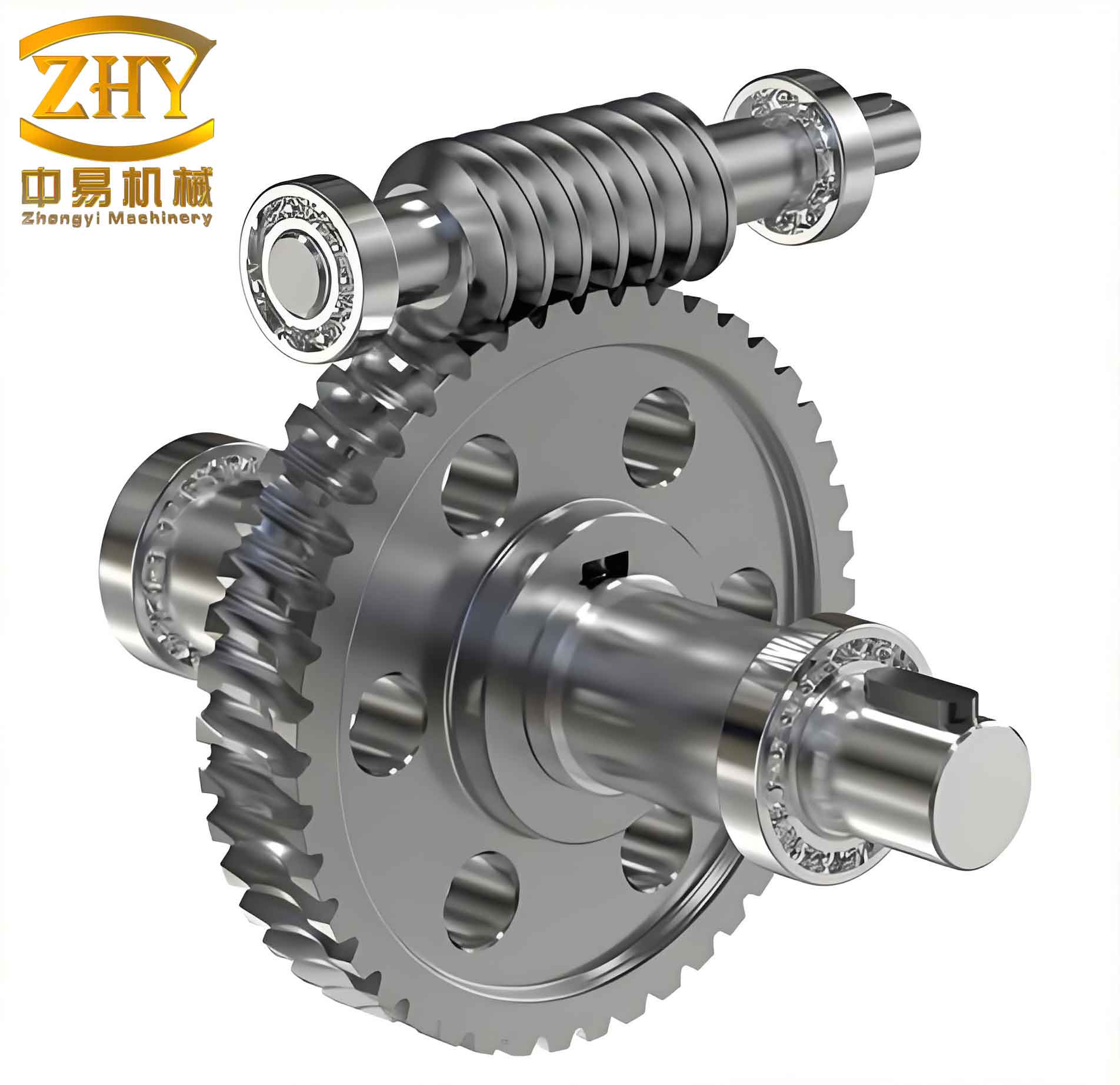
Once the worm and worm gear are modeled, I import them into the UGNX assembly environment and apply appropriate mating conditions (e.g., center distance alignment, angular positioning) to obtain the assembled worm gear pair. The assembly model allows me to perform static interference checks and dynamic collision analysis. It also enables motion simulation to visualize the meshing process. The parametric nature of the models means that any change to the input parameters (module, number of teeth, pressure angle, etc.) automatically updates the geometry, making design iterations efficient.
Mathematical Foundation of Worm Gear Geometry
Understanding the underlying mathematics is critical for parametric modeling. The lead angle \(\gamma\) of the worm satisfies:
$$ \tan \gamma = \frac{z_1 m_{ax}}{d_1} = \frac{1 \cdot 2}{26} \approx 0.07692 \quad \Rightarrow \quad \gamma \approx 4^\circ23’55” $$
The axial pitch \(p_{ax} = \pi m_{ax}\) and the lead \(L = z_1 p_{ax}\). For the worm gear, the normal module is related to the axial module by \(m_n = m_{ax} \cos \gamma\). The center distance is:
$$ a = \frac{d_1 + d_2}{2} = \frac{26 + 54}{2} = 40 \text{ mm} $$
The throat diameter of the worm gear is given by:
$$ d_t = d_2 + 2m_n = 54 + 4 = 58 \text{ mm} $$
These formulas ensure that the worm and worm gear mesh correctly.
Advantages of Parametric Modeling in UGNX
My approach fully exploits the parametric and feature‑based capabilities of UGNX. The use of expressions allows me to define geometric relationships that automatically update when a driving parameter is changed. For example, if I modify the module, all dependent dimensions (pitch diameters, addendum/dedendum, helix lead) recalculate, and the solids regenerate automatically. The combination of sketch‑based parametrics and feature parametrics provides a robust foundation for customized design of worm gears. Below is a summary table of the key parametric relationships used in the modeling:
| Part | Relationship | Equation |
|---|---|---|
| Worm | Pitch diameter | \(d_1 = z_1 m_{ax} / \tan \gamma\) |
| Worm | Addendum diameter | \(d_{a1} = d_1 + 2m_{ax}\) |
| Worm | Dedendum diameter | \(d_{f1} = d_1 – 2.4m_{ax}\) |
| Worm | Lead | \(L = \pi m_{ax} z_1\) |
| Worm Gear | Pitch diameter | \(d_2 = m_n z_2 / \cos \gamma\) |
| Worm Gear | Base circle radius | \(r_b = (d_2 / 2) \cos \alpha\) |
| Worm Gear | Throat diameter | \(d_t = d_2 + 2m_n\) |
| Both | Center distance | \(a = (d_1 + d_2)/2\) |
Conclusion
Through this detailed parametric modeling process of an Archimedean worm gear pair using UGNX, I have demonstrated the power of combining feature‑based and sketch‑based parametrics. The ability to define complex tooth profiles via law curves, helices, and swept operations, while keeping all dimensions linked through expressions, significantly streamlines the design cycle and ensures geometric accuracy. Although UGNX has a steeper learning curve, its flexibility for handling complex shapes like worm gear profiles is unmatched. The solid models created serve as a foundation for subsequent assembly, interference detection, finite element analysis, and motion simulation, enabling deeper investigation into meshing characteristics, surface behavior, and performance optimization of worm gear drives.