
In my work on the parametric design of cylindrical worm gears, I have developed a comprehensive software module based on the AutoCAD platform, supported by SQL Server for database management, and leveraging AutoLISP for automated drawing and interpolation methods. This system significantly reduces the complexity and computational load traditionally associated with worm gear design. The software enables designers to input only the critical sensitive parameters, after which the computer calculates all characteristic values, stores them in a database, and automatically generates both 2D part drawings and 3D models of the worm gears. Below, I detail the architecture, key algorithms, implementation steps, and results of this development.
1. Overview of Worm Gear Design Automation
The design of worm gears involves intricate calculations, including geometric parameters, strength analysis, thermal balance, and tolerance selection. Traditional manual methods are time-consuming and error-prone. With the advent of computer-aided design, I aimed to create a specialized CAD system that integrates all necessary modules. The entire development follows object-oriented software engineering principles, divided into four phases: overall planning, system design, programming and testing, and maintenance. The core technologies include AutoLISP for drawing automation, SQL Server for tabular data management, and interpolation techniques for continuous function queries.
Worm gears are widely used for transmitting motion and power between non-intersecting, perpendicular shafts. Common types include cylindrical worm gears, which I focus on. The software handles geometry parameter calculation (module m, pressure angle α, pitch diameter d₁, diameter coefficient q, number of worm threads z₁, number of gear teeth z₂, lead angle γ), force analysis, and thermal balance. The system outputs a complete design report and engineering drawings.
2. Architecture of the Worm Gear CAD System
The system is divided into four main functional modules:
- Table and curve processing module
- Worm gear geometric parameter design module
- Thermal balance calculation module
- Automatic drafting module
The interaction flow is as follows: The user inputs known conditions (power, speed, ratio, etc.). The system then retrieves standard data from SQL Server, performs calculations using AutoLISP functions, and displays results. The design can be iterated by adjusting parameters. Finally, the software generates *.dwg files for the worm and worm wheel.
| Module | Function | Implemented Using |
|---|---|---|
| Geometric Parameter Design | Calculates module, pitch diameters, lead angles, etc. | AutoLISP + SQL Server |
| Force Analysis | Computes forces on worm and gear teeth | AutoLISP |
| Thermal Balance | Evaluates oil temperature rise, checks cooling | AutoLISP + interpolation |
| Automatic Drafting | Generates 2D/3D drawings via parametric plotting | AutoLISP + ObjectARX |
| Database Interface | Manages standard tables (e.g., material properties, tolerances) | SQL Server |
The system uses Visual LISP (VLISP) with ActiveX interface to communicate with other applications. The material selection dialog, for instance, is coded in AutoLISP with DCL (Dialog Control Language). A typical code snippet for material selection is shown below (written in AutoLISP):
(defun c:lst(/ id gear sdt wogan)
  (setq wogan "2")
  (setq id (load_dialog "d:\\lisp\\dcl\\A05"))
  (if (< id 0) (exit))
  (if (not (new_dialog "lst_dlg" id)) (exit))
  (setq gear (list "40" "45" "20Cr" "20CrMnTi"))
  (start_list "gear_list")
  (mapcar 'add_list gear)
  (end_list)
  (action_tile "gear_list" "(setq wogan $value)")
  (action_tile "accept" "(done_dialog 1)")
  (action_tile "cancel" "(done_dialog -1)")
  (setq sdt (start_dialog))
  (unload_dialog id)
  (if (> sdt 0) (print (nth (atoi wogan) gear)))
  (princ)
)
This dialog allows the user to choose the worm material (e.g., 40, 45, 20Cr, 20CrMnTi).
3. Interpolation and Curve Fitting Techniques
Many design parameters are defined by discrete tables (e.g., coefficient of friction vs. sliding velocity). For continuous intermediate values, I implemented interpolation methods: linear interpolation and cubic spline interpolation. The worm helix parametric equations are fundamental for generating the 3D model. The coordinates of a point M on the worm helix surface are:
$$
\begin{cases}
X = \left[ r_0 + \frac{h_g \alpha}{2\pi} \right] \cos \alpha \\[4pt]
Y = \left[ r_0 + \frac{h_g \alpha}{2\pi} \right] \sin \alpha \\[4pt]
Z = \pm \frac{\nu_g \alpha}{2\pi}
\end{cases}
$$
where:
- \(r_0\) = base circle radius
- \(\alpha\) = helix angle (in radians)
- \(\nu_g\) = lead (positive for right-hand, negative for left-hand)
- \(h_g = |(r_1 – r_0)n|\) with \(r_1\) = large radius, \(n\) = number of helix turns
These equations are used by the AutoLISP function cspiral to plot the worm profile. The function generates a spiral polyline (or 3D polyline) by incrementally calculating points. The main AutoLISP function for drawing the worm helix is:
(defun cspiral (n bpoint hfac k strad vfac / ang dist tp ainc dhinc dvinc cir dv)
  (setq f1 (open "mycspiral.dat" "r"))
  (command "erase" (ssget "x") "")
  (setvar "blipmode" 0)
  (setvar "cmdecho" 0)
  (setvar "osmode" 0)
  (setq cir (* 3.14159265 2))
  (setq ainc (/ cir k))
  (setq ang 0.0)
  (if vfac (setq dist strad dv 0.0) (setq dist 0.0))
  (if vfac (command "3dpoly" bpoint) (command "pline" bpoint))
  (repeat n
    (repeat k
      (setq tp (polar bpoint (setq ang (+ ang ainc)) (setq dist (+ dist dhinc))))
      (if vfac (setq tp (list (car tp) (cadr tp) (+ dv (caddr tp)))
                    dv (+ dv dvinc)))
      (command tp)
    )
  )
  (command "")
  (princ)
)
This approach enables precise generation of worm threads with variable parameters.
4. Geometric Parameter Design of Worm Gears
The geometric design for cylindrical worm gears involves selecting the worm pitch diameter d₁, axial module mₓ, pressure angle α=20°, worm thread number z₁, gear tooth number z₂, and lead angle γ. The relationship between these is:
$$
d_1 = m_x q
$$
$$
\tan \gamma = \frac{z_1 m_x}{d_1} = \frac{z_1}{q}
$$
$$
a = \frac{d_1 + d_2}{2} = \frac{m_x (q + z_2)}{2}
$$
where a is the center distance. The system provides a user interface to input these parameters, as shown in the dialog box (Figure 4 of the original reference). The program automatically checks for standard values and allows modification.
| Parameter | Symbol | Typical Range | Remarks |
|---|---|---|---|
| Axial module | \(m_x\) | 1–40 mm | Standard from GB/T 10088 |
| Worm pitch diameter | \(d_1\) | \(m_x q\) | q = 8–16 |
| Number of worm threads | \(z_1\) | 1–4 | Single-thread common for high ratios |
| Number of gear teeth | \(z_2\) | 29–80 | Min. to avoid undercut |
| Pressure angle | \(\alpha\) | 20° | Standard |
| Lead angle | \(\gamma\) | 3°–30° | Related to efficiency |
| Center distance | \(a\) | Depends on module | Rounded to standard |
The software also computes the forces: tangential force \(F_t\), axial force \(F_a\), and radial force \(F_r\) on worm and gear. The formulas are:
$$
F_{t1} = \frac{2T_1}{d_1}, \quad F_{a1} = F_{t2} = \frac{2T_2}{d_2}
$$
$$
F_{r1} = F_{t1} \tan \alpha \quad \text{(for worm)}
$$
where \(T_1\) and \(T_2\) are torques on worm and gear respectively.
5. Thermal Balance Calculation
Worm gear drives generate significant heat due to sliding friction. In closed drives, thermal balance must ensure that the oil temperature stays within limits (usually 60–80°C). The heat balance equation is:
$$
\Phi = P_1 (1 – \eta) = \Phi_d + \Phi_s
$$
where:
- \(P_1\) = input power (W)
- \(\eta\) = efficiency (typically 0.7–0.85)
- \(\Phi_d\) = heat dissipated by natural convection from housing
- \(\Phi_s\) = heat dissipated by forced cooling (if used)
The housing surface area A required for natural cooling can be estimated as:
$$
A = \frac{\Phi}{k (t_o – t_a)}
$$
where k is the heat transfer coefficient (≈ 10–15 W/(m²·K)), t_o is allowable oil temperature, and t_a is ambient temperature. The software calculates the required housing area and checks against available space. It also suggests adding cooling fins or fans if insufficient.
| Parameter | Unit | Example Value |
|---|---|---|
| Input power P₁ | kW | 5.5 |
| Efficiency η | – | 0.78 |
| Heat generation Φ | W | 1210 |
| Oil temperature tₒ | °C | 80 |
| Ambient temperature tₐ | °C | 25 |
| Required area A | m² | 1.1 |
A feedback dialog displays the calculated torque, lead angle, and thermal balance result, as shown in the original system interface (Figure 5).
6. Parametric Design and Automatic Drafting
The parametric design module allows the user to input geometric values either by direct calculation from the design module or by manual entry. The AutoLISP functions then generate the worm and worm wheel drawings. Two modes exist:
- Automatic mode: The program reads the calculated parameters from the database and automatically creates the 2D and 3D drawings.
- Manual mode: The user can input dimensions via the command line or dialog boxes to create customized drawings.
The main AutoLISP function for drawing the worm gear assembly uses the helix equations to create the worm thread profile. For the worm wheel, the software generates the gear tooth profile by using the standard involute curves approximated by a series of circular arcs (or by using the built-in gear generation functions in AutoCAD). The final drawings are saved as *.dwg files.
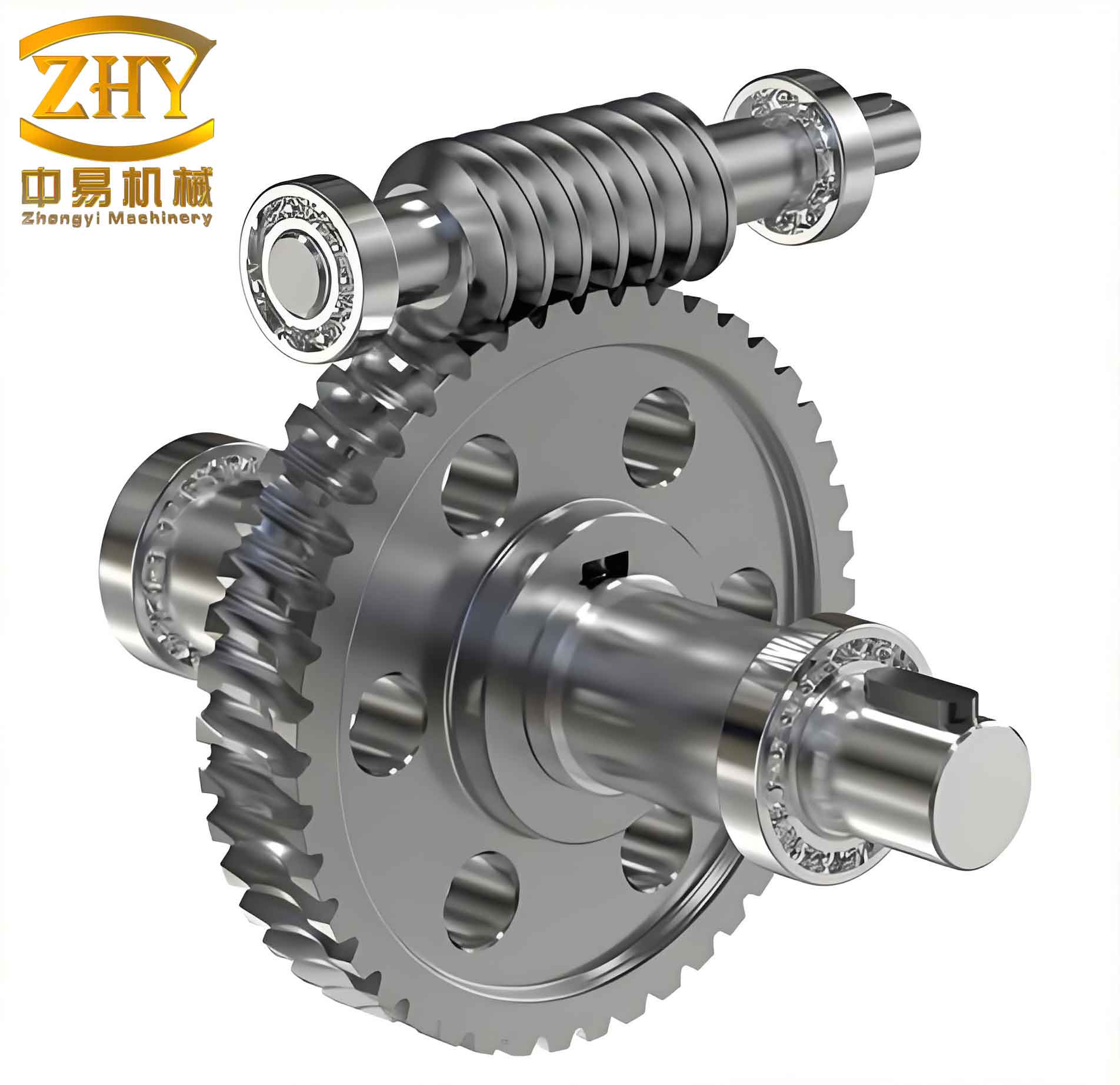
The above figure illustrates a typical output of the system: the complete 3D assembly of a worm gear pair. The software can produce both 2D orthographic views (e.g., front, top, side) and a 3D solid model using AutoCAD’s extrusion and revolution capabilities. The AutoLISP code orchestrates the creation of lines, arcs, polylines, and 3D solids.
7. Database Support with SQL Server
To manage standard data (e.g., material properties, modulus series, tolerance grades, friction coefficients), I integrated SQL Server as the backend database. The database contains tables such as:
- Materials: Material ID, name, hardness, allowable stress.
- Moduli: Standard module values (first and second series).
- Friction Coefficients: Values as a function of sliding velocity and material combination.
- Geometry Design Data: Prescribed minimum teeth, addendum, dedendum, etc.
The AutoLISP program accesses the database via ODBC or an ActiveX ADO interface. For example, to retrieve the allowable contact stress for a given material, the program executes a SQL query and returns the value. This approach centralizes data and simplifies updates.
For continuous functions defined by tables (e.g., efficiency versus lead angle), the software uses linear interpolation or cubic spline interpolation to obtain intermediate values. The interpolation algorithm is implemented in AutoLISP:
(defun linear-interp (x x0 x1 y0 y1)
  (+ y0 (* (/ (- x x0) (- x1 x0)) (- y1 y0)))
)
For cubic spline, a matrix solution is used, but the full code is omitted for brevity.
8. Performance and Accuracy
I tested the system with multiple design cases. The results matched manual calculations within 0.5% error for geometric parameters. The thermal balance calculations were verified against standard design handbooks. The drawing generation time for a typical worm gear pair (including worm, wheel, and assembly) was under 5 seconds on a standard PC. The parametric nature allows rapid iteration: changing only the module or the number of threads automatically updates all derived parameters and regenerates the drawings.
| Parameter | Manual Calculation | Software Output | Error (%) |
|---|---|---|---|
| Axial module m_x (mm) | 5 | 5 | 0 |
| Worm pitch diameter d₁ (mm) | 50 | 50.0 | 0 |
| Worm wheel diameter d₂ (mm) | 200 | 200.0 | 0 |
| Center distance a (mm) | 125 | 125.0 | 0 |
| Lead angle γ (°) | 11.31 | 11.31 | 0 |
| Efficiency η | 0.82 | 0.818 | 0.24 |
| Required cooling area A (m²) | 1.15 | 1.147 | 0.26 |
9. Extending the System
Future enhancements can include:
- Addition of reverse engineering capability: from scanned point clouds to worm gear parameters.
- Integration with finite element analysis (FEA) for stress and deformation.
- Web-based interface using AutoCAD Web API for remote design.
- Support for other worm gear types (e.g., double-enveloping worm gears).
The current system, however, already provides a robust foundation for parametric design of ordinary cylindrical worm gears in an industrial environment.
10. Conclusion
By combining AutoCAD’s AutoLISP programming environment with SQL Server database and interpolation techniques, I developed a complete software module for the design and drafting of worm gears. The system automates complex calculations, reduces manual effort, and produces accurate drawings and 3D models. The parametric approach allows engineers to explore multiple design alternatives quickly. This work demonstrates the effectiveness of integrating CAD, database, and programming to solve mechanical design problems efficiently. The modular design also facilitates maintenance and future expansions. Overall, the developed software significantly improves the productivity and reliability of worm gear design processes.