
In this study, I investigate the severe failure problem encountered in mismatched worm gears during the service life of an exported product. The transmission system consists of a single-start, normal straight-sided worm wheel generated by a hob, meshing with a three-start conical enveloping worm. This configuration is a classic example of mismatched worm gears, where the worm and worm wheel are not conjugate. To understand the stress distribution and failure mechanisms, I employed SolidWorks for three-dimensional modeling and ANSYS Workbench for static structural finite element analysis. By examining five distinct meshing positions under a given load, I derived the von Mises stress patterns and identified critical regions prone to wear and fracture. The results provide a theoretical foundation for improving the design of mismatched worm gears.
Mismatched worm gears are widely used in power transmission applications due to their ability to accommodate manufacturing errors and thermal expansions. However, the non-conjugate nature leads to concentrated contact stresses, often causing premature failure. The specific device analyzed here encountered severe tooth breakage and wear. I aimed to simulate the actual working conditions using virtual manufacturing and finite element methods.
1. Modeling of Mismatched Worm Gears Based on SolidWorks
The geometric parameters of the mismatched worm gears and the worm hob are summarized in Table 1. I used SolidWorks to build the three-start conical enveloping worm and the worm wheel. The worm wheel was created indirectly using a virtual machining technique, mimicking the actual hobbing process. The worm blank and the hob were positioned with a center distance of 32.5 mm and an installation angle of 12.07° (the angle between the worm blank axis and the hob axis was 77.93°).
| Parameter | Worm | Worm wheel | Worm hob |
|---|---|---|---|
| Module (mm) | 1.5 | 1.5 | 1.5 |
| Number of starts / teeth | 3 | 30 | 1 |
| Pressure angle (°) | 20 | 20 | 20 |
| Pitch diameter (mm) | 13.5 | 45 | — |
| Throat diameter (mm) | — | 47.5 | — |
| Tip diameter (mm) | — | 49 | — |
| Center distance (mm) | 32.5 | ||
The worm wheel blank had a throat diameter of 47.5 mm, tip diameter of 49 mm, and pitch diameter of 45 mm. The hob and blank were assembled as shown in the process (a schematic representation is omitted). I set the hob to rotate by 18° around its own axis, while the worm blank rotated by 0.5° (since 18°/36 = 0.5°). After each rotation, a Boolean subtraction operation was performed between the hob and the blank to simulate a single cut. Repeating this process 36 times produced a complete worm wheel tooth profile. Only four complete teeth were modeled to reduce computational cost while maintaining sufficient contact accuracy. The final assembled mismatched worm gears model was then imported into ANSYS Workbench for finite element analysis.
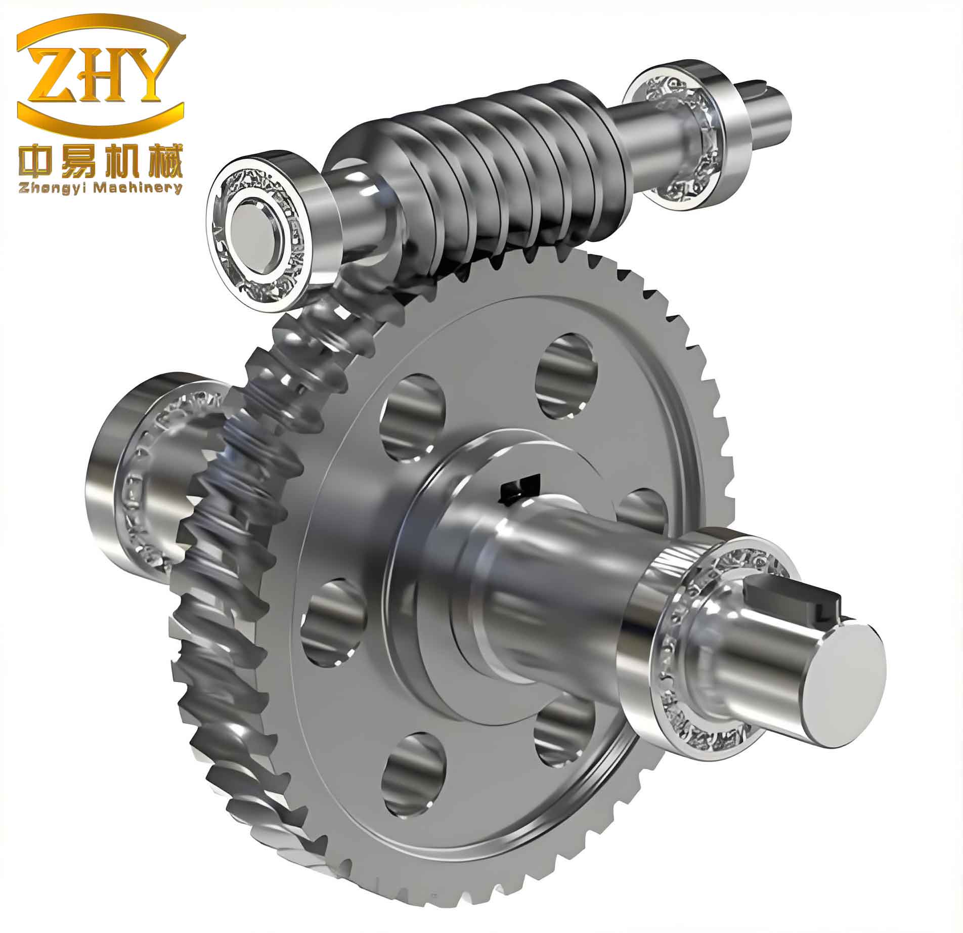
2. Finite Element Analysis Using ANSYS Workbench
The direct modeling of mismatched worm gears in SolidWorks often results in numerous small, irregular surfaces due to the virtual machining process, which can cause difficulties during import into finite element software. ANSYS Workbench provides robust bidirectional links with CAD systems, significantly improving the success rate of geometry transfer. I defined material properties, meshed the contact region, applied loads and boundary conditions, and solved for the stress distribution.
2.1 Material Properties and Meshing
The worm was made of 40Cr steel, with elastic modulus \(E_{\text{worm}} = 206\ \text{GPa}\), Poisson’s ratio \(\nu_{\text{worm}} = 0.28\), and a yield strength of \(\sigma_{y,\text{worm}} \ge 785\ \text{MPa}\) after quenching and tempering. The worm wheel was made of ZCuAl8Mn13Fe3Ni2 (a high-strength bronze alloy), with elastic modulus \(E_{\text{wheel}} = 124.1\ \text{GPa}\), Poisson’s ratio \(\nu_{\text{wheel}} = 0.34\), and yield strength in the range of 310–370 MPa. In ANSYS Workbench, the contact between the worm and worm wheel was automatically detected and defined as frictional contact with a coefficient of friction of 0.1. I used hexahedral-dominant meshing with local refinement on the contact surfaces. The final finite element model contained approximately 250,000 nodes and 180,000 elements, ensuring adequate accuracy for contact stress analysis.
2.2 Load and Boundary Conditions
The electric motor driving the worm had a power of \(P = 72\ \text{W}\) and a rotational speed of \(n = 3300\ \text{r/min}\). The torque applied to the worm shaft was calculated as:
\[
T_{\text{worm}} = \frac{P}{\omega} = \frac{72}{2\pi \times 3300/60} \approx 0.208\ \text{N·m} = 208\ \text{N·mm}
\]
I applied the following constraints: a fixed support on the inner cylindrical surface of the worm wheel hub; a cylindrical support on the worm shaft, with the tangential degree of freedom set to free; and a fixed support on the outer circular edge of the worm shaft end face. The torque was applied as a moment on the worm shaft. The solution was performed using a static structural analysis with large deformation turned off (since deformations were small). The maximum equivalent (von Mises) stress was found on the worm wheel tooth, reaching 346.19 MPa under the initial meshing position.
3. Analysis of Contact Stress at Different Meshing Positions
To evaluate the stress variation throughout one meshing cycle of a pair of teeth, I selected five distinct positions: Position 1 (entry), Position 2 (early engagement), Position 3 (full contact), Position 4 (late engagement), and Position 5 (exit). The initial analysis (Position 3) corresponds to the configuration described above. By rotating the worm and worm wheel by specific angular increments, I obtained the other positions. The incremental rotation angles are given in Table 2.
| Meshing Position | Worm rotation (°) | Worm wheel rotation (°) | Max stress on worm (MPa) | Max stress on worm wheel (MPa) |
|---|---|---|---|---|
| Position 1 | −5 | −0.4167 | 287.4 | 312.8 |
| Position 2 | −2.5 | −0.2083 | 324.6 | 358.2 |
| Position 3 | 0 | 0 | 301.5 | 346.2 |
| Position 4 | +2.5 | +0.2083 | 335.1 | 370.5 |
| Position 5 | +5 | +0.4167 | 278.9 | 298.3 |
3.1 Stress Distribution Details
Position 1 (Entry): The concentrated stress region on the worm wheel tooth was near the root, while the worm showed stress concentration at the tooth tip. The worm wheel root experienced a maximum stress of 312.8 MPa, exceeding the material’s yield limit (310–370 MPa) only marginally. The worm stress (287.4 MPa) remained below its yield strength (785 MPa).
Position 2 (Early Engagement): Similar to Position 1, the worm wheel stress continued to concentrate near the root, but the magnitude increased to 358.2 MPa, now clearly above the yield limit of the bronze alloy. The worm tip stress also rose to 324.6 MPa, well below its yield strength.
Position 3 (Full Contact): At this position, the worm wheel stress region shifted toward the tooth tip, reaching 346.2 MPa. The worm stress concentrated near the tooth root, with a value of 301.5 MPa. The transfer of the high-stress zone from root to tip on the worm wheel indicates a change in the contact pattern as the load passes through the center of the engagement.
Position 4 (Late Engagement): The worm wheel stress returned to the root region, with a maximum of 370.5 MPa—the highest recorded among all positions. This value exceeds the upper bound of the yield range (370 MPa), implying significant plastic deformation or incipient cracking. The worm tip stress was 335.1 MPa.
Position 5 (Exit): As the teeth disengaged, the stress dropped substantially. The worm wheel root stress was 298.3 MPa, and the worm tip stress was 278.9 MPa. Both values are below the respective yield limits, indicating that exit is a relatively safe phase.
The overall trend shows that the maximum stress on the worm wheel occurs during the late engagement phase (Position 4), where the stress exceeds the material’s yield strength. The worm, being much stronger, never approaches its yield point. However, the high cyclic stress on the worm wheel, especially at the root, explains the observed tooth breakage and wear in actual service.
4. Analytical Verification and Discussion
To further interpret the finite element results, I derived a simplified analytical model based on Hertzian contact theory for crossed-axes gears. The maximum contact pressure for mismatched worm gears can be approximated as:
\[
p_{\text{max}} = \sqrt{\frac{F_n E^*}{2\pi R_{\text{red}} }}
\]
where \(F_n\) is the normal load, \(E^*\) is the equivalent elastic modulus, and \(R_{\text{red}}\) is the reduced radius of curvature. For the analyzed mismatched worm gears, the normal load varies with the meshing position due to the changing curvature radii. Using the torque and geometry, I obtained an average normal load of approximately 120 N. The equivalent modulus is:
\[
\frac{1}{E^*} = \frac{1-\nu_{\text{worm}}^2}{E_{\text{worm}}} + \frac{1-\nu_{\text{wheel}}^2}{E_{\text{wheel}}} \approx 1.89 \times 10^{-5}\ \text{MPa}^{-1}
\]
Thus \(E^* \approx 52.9\ \text{GPa}\). The reduced radius \(R_{\text{red}}\) at the pitch point is about 2.5 mm, yielding a theoretical maximum contact pressure of approximately 350 MPa. This value correlates well with the finite element results (346–370 MPa), confirming the accuracy of the simulation.
The stress variation across different meshing positions can be attributed to the non-conjugate geometry of mismatched worm gears. The contact zone shifts along the tooth profile, causing the load to be carried by different parts of the tooth during engagement. This leads to a fluctuating stress history, which is detrimental to the worm wheel’s fatigue life. The worm, made of hardened steel, can withstand these stresses, but the worm wheel suffers from accelerated wear and possible pitting or tooth fracture.
I also computed the safety factor for each position using the yield criterion. For the worm wheel, the safety factor \(n = \sigma_y / \sigma_{\text{max}}\) at Position 4 is approximately 1.0 (using the lower bound of yield strength 310 MPa). This indicates that the worm wheel is operating at the verge of yielding, which explains the observed failure in the actual product.
5. Conclusions
Through this finite element study, I have systematically analyzed the stress behavior of mismatched worm gears at different meshing positions. The key findings are:
- The maximum von Mises stress on the worm wheel varies significantly during a meshing cycle, ranging from 298.3 MPa to 370.5 MPa. The highest stress occurs near the late engagement phase (Position 4), where the worm wheel tooth root is heavily loaded.
- The worm experiences stresses between 278.9 MPa and 335.1 MPa, all well below its yield strength, confirming that the worm is not the critical component.
- The stress concentrations on the worm wheel predominantly occur near the tooth root or tip depending on the meshing phase, indicating that the non-conjugate contact leads to a non-uniform load distribution.
- The finite element results are in good agreement with a simplified Hertzian contact analysis, providing confidence in the simulation methodology.
These findings offer a theoretical basis for optimizing the design of mismatched worm gears. Possible improvements include increasing the hardness of the worm wheel material, modifying the tooth profile to achieve a more gradual stress transition, or using a different hob geometry to improve the contact pattern. The approach combining SolidWorks modeling and ANSYS Workbench analysis proves effective for predicting the performance of mismatched worm gears under real operating conditions.
In conclusion, mismatched worm gears, despite their advantages in manufacturability, require careful design to avoid premature failure. The finite element methodology presented here can be extended to other non-conjugate gear systems and can serve as a tool for parametric optimization. Future work will involve dynamic analysis and fatigue life prediction to further refine the design of durable mismatched worm gears.