
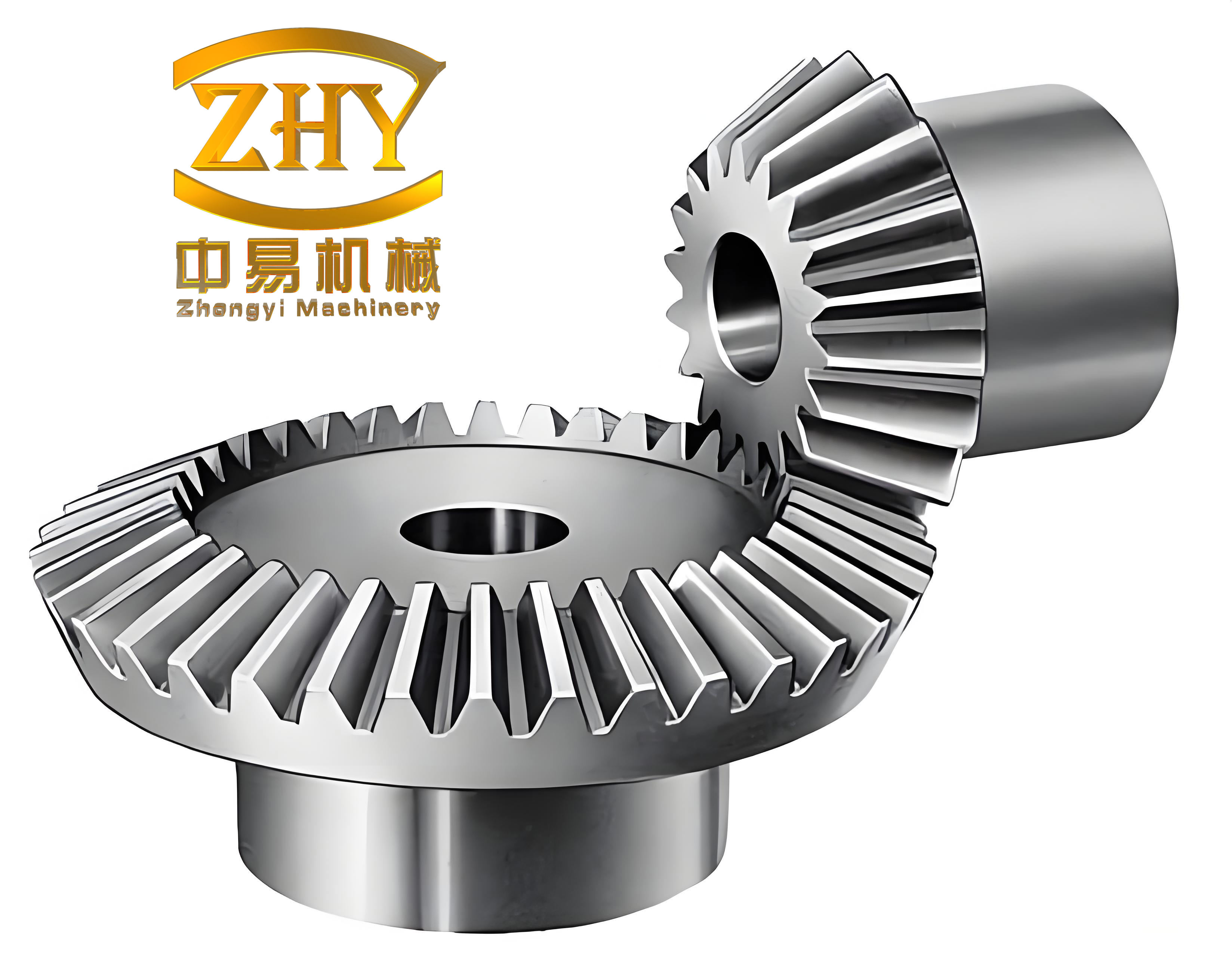
I treat the differential as a compact torque-splitting mechanism whose main task is to send engine power to the wheels while allowing the two driven wheels to rotate at different speeds during turning. In a farm vehicle, this function is often performed by a set of straight bevel gears because they are robust, easy to manufacture, and well suited to the moderate speeds and high loads found in agricultural service. The differential case carries the ring gear torque, the planet gears rotate on a cross pin, and the two side gears drive the axle shafts. The quality of the straight bevel gears directly affects power transmission efficiency, steering behavior, and durability. My design method therefore begins with load definition, then moves to main parameter selection, geometry calculation, bending strength verification, and finally manufacturing and assembly checks.
Load Cases and Design Torque
I define the differential calculation torque from the smaller of two limiting values: the torque that the engine and clutch can deliver, and the torque that the road adhesion can transmit. This prevents the straight bevel gears from being sized for a load that cannot physically occur. I use the following basic relationships:
$$T_d = \min(T_{ce}, T_{cs})$$
$$T_0 = T_d$$
$$T = 0.6 T_0$$
Here, \(T_{ce}\) is the engine-side torque limit, \(T_{cs}\) is the adhesion-side torque limit, \(T_d\) is the differential calculation torque, \(T_0\) is the torque transmitted by the differential case, and \(T\) is the side gear calculation torque used in bending strength. For fatigue checking, I also use a frequent torque case \(T_{cf}\). The allowable bending stress depends on which torque case is being checked.
| Load case | Meaning | Torque used | Allowable bending stress |
|---|---|---|---|
| Engine-limited | Maximum torque that can be delivered through the clutch | \(T_{ce}\) | Part of \(T_d = \min(T_{ce}, T_{cs})\) |
| Adhesion-limited | Maximum torque that the tires can transmit to the road | \(T_{cs}\) | Part of \(T_d = \min(T_{ce}, T_{cs})\) |
| Differential calculation | Smaller of engine and adhesion limits | \(T_d\) | \([\sigma_w] = 980 \text{ MPa}\) |
| Fatigue | Frequent service torque | \(T_{cf}\) | \([\sigma_w] = 210 \text{ MPa}\) |
I use \(T_0 = T_d\) for the differential case torque. When I calculate the bending stress of the side gear, I take \(T = 0.6T_0\). This reduced torque reflects the fact that the differential divides the total torque between two side gears, and it also accounts for the unequal torque distribution that can occur during turning or when one wheel slips.
Main Parameter Selection
Number of Planet Gears
I select the number of planet gears, \(n\), first because it controls the load-sharing behavior and the assembly condition. For a farm vehicle differential, four planet gears are common. This gives good load distribution, balanced support, and a compact package. The number of planet gears also determines which side gear tooth counts can be assembled.
| Application | Typical \(n\) | Reason |
|---|---|---|
| Light farm vehicle | 2 | Simple, low cost, lower torque |
| Medium farm vehicle | 4 | Balanced load, common for trucks |
| Heavy duty | 4 or more | Higher torque capacity, but more complex |
The assembly condition for four planet gears is that the sum of the two side gear tooth counts must be divisible by the number of planet gears:
$$\frac{2Z_2}{n} \in \mathbb{Z}$$
For \(n=4\), this means \(2Z_2\) must be divisible by 4, so \(Z_2\) must be even. I check this condition before fixing the tooth counts.
Spherical Radius and Pitch Cone Distance
I determine the planet gear spherical radius, \(R_B\), from an empirical relationship that scales with the cube root of the differential calculation torque:
$$R_B = K_B \sqrt[3]{T_d}$$
Here, \(K_B\) is the spherical radius coefficient. For highway or farm truck differentials, \(K_B\) is usually between 2.5 and 3.0. I take the smaller value when I want a compact design and the larger value when I want more strength. The pitch cone distance \(A_0\) is then obtained from:
$$A_0 = (0.98 \sim 0.99) R_B$$
| Parameter | Range or value | Comment |
|---|---|---|
| \(K_B\) | 2.5 to 3.0 | Take smaller for compact road vehicles |
| \(R_B\) | From \(K_B \sqrt[3]{T_d}\) | Spherical radius of planet gear |
| \(A_0\) | \((0.98 \sim 0.99) R_B\) | Pitch cone distance of straight bevel gears |
For my example, \(T_d = 3165 \text{ N·m}\) and \(K_B = 2.6\). This gives \(R_B = 36.6 \text{ mm}\), which I round to 36 mm. Then \(A_0 = 37 \text{ mm}\). I use this preliminary value to estimate the module and tooth counts. After the tooth geometry is fixed, I recalculate the exact pitch cone distance from the pitch diameters and cone angles.
Planet Gear and Side Gear Tooth Counts
I want the straight bevel gears to have high tooth strength, so I generally use a larger module and a smaller planet gear tooth count. However, the planet gear tooth count \(Z_1\) must not be less than 10. The side gear tooth count \(Z_2\) is usually selected between 14 and 25. The ratio \(Z_2/Z_1\) should be between 1.5 and 2.0. This ratio affects the torque split, the size of the side gears, and the smoothness of the differential action.
| Parameter | Recommended range | Design reason |
|---|---|---|
| \(Z_1\) | \(Z_1 \ge 10\) | Undercut limit and strength |
| \(Z_2\) | 14 to 25 | Size and ratio balance |
| \(Z_2/Z_1\) | 1.5 to 2.0 | Torque split and compactness |
| Assembly | \(2Z_2/n \in \mathbb{Z}\) | Planet gears must mesh with both side gears |
For my example, I choose \(Z_1 = 10\) and \(Z_2 = 16\). The ratio is 1.6, which is inside the recommended range. The sum of the two side gear tooth counts is 32, and 32 is divisible by \(n=4\), so the four planet gears can be assembled with equal spacing. This is an important check for any set of straight bevel gears used in a differential.
| \(Z_1\) | \(Z_2\) | Ratio \(Z_2/Z_1\) | \(2Z_2\) | Divisible by 4? |
|---|---|---|---|---|
| 10 | 14 | 1.40 | 28 | No |
| 10 | 16 | 1.60 | 32 | Yes |
| 10 | 18 | 1.80 | 36 | Yes |
| 11 | 16 | 1.45 | 32 | Yes |
| 12 | 18 | 1.50 | 36 | Yes |
| 12 | 20 | 1.67 | 40 | Yes |
Pitch Cone Angles and Module
For straight bevel gears with a shaft angle of 90°, I calculate the pitch cone angles from the tooth counts:
$$\gamma_1 = \arctan\left(\frac{Z_1}{Z_2}\right)$$
$$\gamma_2 = \arctan\left(\frac{Z_2}{Z_1}\right)$$
The module is then obtained from the pitch cone distance and the cone angles:
$$m = \frac{2A_0}{Z_1}\sin\gamma_1 = \frac{2A_0}{Z_2}\sin\gamma_2$$
I check that the module calculated from the planet gear and from the side gear is the same. In practice, I round the module to a standard value and then recalculate the exact pitch cone distance. The pitch diameters follow directly:
$$d_1 = m Z_1$$
$$d_2 = m Z_2$$
| Item | Formula | Example value |
|---|---|---|
| Planet gear pitch cone angle | \(\gamma_1 = \arctan(Z_1/Z_2)\) | \(32^\circ\) |
| Side gear pitch cone angle | \(\gamma_2 = \arctan(Z_2/Z_1)\) | \(58^\circ\) |
| Module | \(m = 2A_0 \sin\gamma_1 / Z_1\) | \(4.0 \text{ mm}\) |
| Planet gear pitch diameter | \(d_1 = m Z_1\) | \(40 \text{ mm}\) |
| Side gear pitch diameter | \(d_2 = m Z_2\) | \(64 \text{ mm}\) |
Pressure Angle and Tooth Height
For farm vehicle differential straight bevel gears, I use a pressure angle of \(22^\circ 30’\) and a tooth height coefficient of 0.8. This pressure angle provides a good balance between bending strength and contact stress. It also reduces the risk of undercut for the smaller planet gear. The tooth height coefficient controls the working depth and the clearance.
| Parameter | Value | Effect |
|---|---|---|
| Pressure angle \(\alpha\) | \(22^\circ 30’\) | Higher bending strength than \(20^\circ\) |
| Tooth height coefficient | 0.8 | Controls working depth and clearance |
| Shaft angle \(\Sigma\) | \(90^\circ\) | Standard differential arrangement |
Planet Gear Shaft Diameter and Support Length
The planet gear shaft carries the planet gear load and transmits it to the differential case. I calculate the shaft diameter from the allowable bearing pressure on the support surface. The shaft diameter \(d\) is:
$$d = \sqrt{\frac{T_0 \times 10^3}{1.1\, \sigma_c\, n\, r_d}}$$
Here, \(\sigma_c\) is the allowable compressive stress on the support surface, usually taken as 98 MPa. The distance \(r_d\) is approximately half of the average diameter at the midpoint of the side gear face width. Since the average diameter is about \(0.8d_2\), I use:
$$r_d \approx 0.4 d_2$$
The support length \(L\) of the planet gear on the shaft is:
$$L = 1.1d$$
| Parameter | Formula | Example value |
|---|---|---|
| Allowable compressive stress | \(\sigma_c = 98 \text{ MPa}\) | 98 MPa |
| Support radius | \(r_d \approx 0.4d_2\) | \(25.6 \text{ mm}\) |
| Shaft diameter | \(d = \sqrt{T_0 \times 10^3 / (1.1\sigma_c n r_d)}\) | \(17.4 \text{ mm}\) |
| Support length | \(L = 1.1d\) | \(19.1 \text{ mm}\) |
Geometry Calculation of Straight Bevel Gears
After the main parameters are selected, I calculate the complete tooth geometry. I use a systematic table so that each item is calculated once and checked against the previous results. The following table applies to straight bevel gears, zero spiral bevel gears, and spiral bevel gears with the same basic proportions. For modules that fall between two rows in a backlash table, I take the smaller value from the upper row for a conservative design. For automotive main reducers, the high-precision backlash column is normally used; for differential straight bevel gears, I use the appropriate precision column according to the manufacturing process.
| Step | Item | Formula | Example |
|---|---|---|---|
| 1 | Planet gear tooth count | \(Z_1 \ge 10\), keep small | 10 |
| 2 | Side gear tooth count | \(14 \le Z_2 \le 25\), check assembly | 16 |
| 3 | Module | \(m = 2A_0 \sin\gamma_1 / Z_1\) | 4.000 mm |
| 4 | Face width | \(F = (0.25 \sim 0.30)A_0\), \(F \le 10m\) | 11.321 mm |
| 5 | Working tooth height | \(h_g = 1.6m\) | 6.400 mm |
| 6 | Whole tooth height | \(H = 1.788m + 0.051\) | 7.203 mm |
| 7 | Pressure angle | \(\alpha = 22^\circ 30’\) | \(22.5^\circ\) |
| 8 | Shaft angle | \(\Sigma = 90^\circ\) | \(90^\circ\) |
| 9 | Pitch diameters | \(d_1 = mZ_1\), \(d_2 = mZ_2\) | 40.000 mm, 64.000 mm |
| 10 | Pitch cone angles | \(\gamma_1 = \arctan(Z_1/Z_2)\), \(\gamma_2 = \arctan(Z_2/Z_1)\) | \(32.000^\circ\), \(58.000^\circ\) |
| 11 | Pitch cone distance | \(A_0 = d_1/(2\sin\gamma_1) = d_2/(2\sin\gamma_2)\) | 37.736 mm |
| 12 | Circular pitch | \(t’ = \pi m\) | 12.566 mm |
| 13 | Addendum heights | \(h_1′ = h_g – h_2’\), \(h_2′ = \left[0.430 + 0.370/(Z_2/Z_1)^2\right]m\) | 4.102 mm, 2.298 mm |
| 14 | Dedendum heights | \(h_1” = 1.788m – h_1’\), \(h_2” = 1.788m – h_2’\) | 3.050 mm, 4.854 mm |
| 15 | Radial clearance | \(C = H – h_g = 0.188m + 0.051\) | 0.803 mm |
| 16 | Root angles | \(\delta_1 = \arctan(h_1”/A_0)\), \(\delta_2 = \arctan(h_2”/A_0)\) | \(4.621^\circ\), \(7.330^\circ\) |
| 17 | Face cone angles | \(\gamma_{01} = \gamma_1 + \delta_2\), \(\gamma_{02} = \gamma_2 + \delta_1\) | \(39.330^\circ\), \(62.621^\circ\) |
| 18 | Root cone angles | \(\gamma_{R1} = \gamma_1 – \delta_1\), \(\gamma_{R2} = \gamma_2 – \delta_2\) | \(27.379^\circ\), \(50.670^\circ\) |
| 19 | Outside diameters | \(d_{01} = d_1 + 2h_1’\cos\gamma_1\), \(d_{02} = d_2 + 2h_2’\cos\gamma_2\) | 46.956 mm, 66.436 mm |
| 20 | Apex to outer edge distances | \(x_{01} = A_0\cos\gamma_1 – h_1’\sin\gamma_1\), \(x_{02} = A_0\cos\gamma_2 – h_2’\sin\gamma_2\) | 29.826 mm, 18.051 mm |
| 21 | Theoretical arc tooth thickness | \(s_1 = t’/2 – (h_1′ – h_2′)\tan\alpha – \tau m\), \(s_2 = t’ – s_1\) | 5.740 mm, 6.826 mm |
| 22 | Backlash | Select from backlash table | 0.102 mm |
| 23 | Chordal tooth thickness | \(S_{x1} = s_1 – s_1^3/(6d_1^2) – B/2\), \(S_{x2} = s_2 – s_2^3/(6d_2^2) – B/2\) | 5.669 mm, 6.762 mm |
| 24 | Chordal tooth height | \(h_{x1} = h_1′ + s_1^2\cos\gamma_1/(4d_1)\), \(h_{x2} = h_2′ + s_2^2\cos\gamma_2/(4d_2)\) | 4.277 mm, 2.395 mm |
The tangential modification coefficient \(\tau\) is used to adjust the tooth thickness so that the sliding conditions and strength balance between the planet gear and side gear are improved. For the example, I use \(\tau = -0.051\). The backlash \(B\) is selected from the recommended range for the module and precision class. The chordal values are then used for inspection and for cutting tool setup.
Backlash Selection
I control backlash carefully because too little backlash causes binding and noise, while too much backlash causes impact and reduced positioning accuracy. The following table gives recommended backlash ranges for straight bevel gears according to module and precision class. For differential straight bevel gears, I usually select a value in the middle of the high-precision range when the gears are lapped, and a value in the low-precision range when the gears are cut and not lapped.
| Module range \(m\) (mm) | Low precision backlash \(B\) (mm) | High precision backlash \(B\) (mm) |
|---|---|---|
| 2.11 to 2.54 | 0.076 to 0.127 | 0.051 to 0.102 |
| 2.54 to 3.18 | 0.102 to 0.203 | 0.076 to 0.127 |
| 3.18 to 4.23 | 0.128 to 0.254 | 0.102 to 0.152 |
| 4.23 to 5.08 | 0.152 to 0.330 | 0.127 to 0.178 |
| 5.08 to 6.35 | 0.203 to 0.405 | 0.152 to 0.203 |
| 6.35 to 7.25 | 0.254 to 0.508 | 0.178 to 0.228 |
| 7.25 to 8.47 | 0.305 to 0.559 | 0.203 to 0.279 |
| 8.47 to 10.15 | 0.381 to 0.635 | 0.254 to 0.330 |
| 10.15 to 12.7 | 0.508 to 0.762 | 0.305 to 0.406 |
| 12.7 to 14.5 | 0.508 to 1.016 | 0.356 to 0.457 |
| 14.5 to 15.9 | 0.635 to 1.143 | 0.406 to 0.559 |
| 16.9 to 20.3 | 0.889 to 1.397 | 0.457 to 0.660 |
| 20.3 to 25.4 | 1.143 to 1.651 | 0.508 to 0.762 |
Bending Strength Calculation
Straight bevel gears in a differential are not continuously meshed. They only rotate relative to one another when the vehicle turns, when the left and right wheels travel different distances, or when one wheel slips. For this reason, bending strength is the primary concern. I use the following bending stress equation:
$$\sigma_w = \frac{2 T k_s k_m}{k_v m b_2 d_2 J n} \times 10^3$$
Here, \(T\) is the side gear calculation torque, \(k_s\) is the size coefficient, \(k_m\) is the face load distribution coefficient, \(k_v\) is the dynamic coefficient, \(m\) is the module, \(b_2\) is the side gear face width, \(d_2\) is the side gear pitch diameter, \(J\) is the geometry factor for bending, and \(n\) is the number of planet gears. I take \(T = 0.6T_0\). The coefficients \(k_v\), \(k_s\), and \(k_m\) are selected using the same principles as for main reducer gears.
| Coefficient | Value in example | Comment |
|---|---|---|
| \(n\) | 4 | Number of planet gears |
| \(J\) | 0.273 | Geometry factor from design chart |
| \(b_2\) | 11.3 mm | Side gear face width |
| \(d_2\) | 64 mm | Side gear pitch diameter |
| \(k_v\) | 1.0 | Dynamic coefficient |
| \(k_s\) | 0.629 | Size coefficient for \(m > 1.6\) mm |
| \(k_m\) | 1.0 | Face load distribution coefficient |
| \(T_0\) | 3165 N·m | Differential calculation torque |
| \(T\) | 1899 N·m | \(T = 0.6T_0\) |
Using the values in the table, I calculate the bending stress for the main load case. The result is approximately 756 MPa. This is below the allowable stress of 980 MPa for the differential calculation torque case, so the straight bevel gears are safe under the maximum load. For the fatigue case, the calculated stress is approximately 227 MPa, which is about 8 percent above the allowable fatigue stress of 210 MPa. This small excess can be accepted when I use better manufacturing quality and a stronger material, or I can increase the spherical radius coefficient, the pitch cone distance, the module, or the face width.
| Check case | Calculated stress | Allowable stress | Result |
|---|---|---|---|
| Differential calculation torque | 756 MPa | 980 MPa | Safe |
| Fatigue torque | 227 MPa | 210 MPa | About 8% over; improve material or geometry |
If the bending stress exceeds the allowable value, I do not immediately change the tooth count. I first increase the pitch cone distance by increasing \(K_B\), because the pitch cone distance controls the module and the overall load capacity. I then increase the module and face width, and I check that the face width does not exceed \(10m\). If the stress is still too high, I adjust the tooth thickness modification or select a higher-strength material and heat treatment.
Example Design Summary
I now summarize the main results of the example design. The straight bevel gears have four planet gears, a planet gear tooth count of 10, a side gear tooth count of 16, and a module of 4.0 mm. The pitch cone angles are \(32^\circ\) and \(58^\circ\), and the pitch cone distance is 37.736 mm. The face width is 11.321 mm, which satisfies both the recommended range and the maximum limit of \(10m\).
| Parameter | Value |
|---|---|
| Number of planet gears \(n\) | 4 |
| Planet gear tooth count \(Z_1\) | 10 |
| Side gear tooth count \(Z_2\) | 16 |
| Tooth ratio \(Z_2/Z_1\) | 1.60 |
| Module \(m\) | 4.000 mm |
| Pitch cone distance \(A_0\) | 37.736 mm |
| Planet gear pitch diameter \(d_1\) | 40.000 mm |
| Side gear pitch diameter \(d_2\) | 64.000 mm |
| Planet gear pitch cone angle \(\gamma_1\) | \(32.000^\circ\) |
| Side gear pitch cone angle \(\gamma_2\) | \(58.000^\circ\) |
| Pressure angle \(\alpha\) | \(22^\circ 30’\) |
| Face width \(F\) | 11.321 mm |
| Working tooth height \(h_g\) | 6.400 mm |
| Whole tooth height \(H\) | 7.203 mm |
| Planet gear shaft diameter \(d\) | 17.4 mm |
| Planet gear support length \(L\) | 19.1 mm |
| Backlash \(B\) | 0.102 mm |
I also check the assembly condition. The two side gear tooth counts sum to 32, which is divisible by the four planet gears. This means the planet gears can be equally spaced and each planet gear can mesh with both side gears. The ratio 1.6 is within the recommended range, so the torque split and the differential action are balanced.
| Assembly check | Condition | Example result |
|---|---|---|
| Equal spacing | \(2Z_2/n \in \mathbb{Z}\) | 32/4 = 8, satisfied |
| Tooth ratio | \(1.5 \le Z_2/Z_1 \le 2.0\) | 1.6, satisfied |
| Planet gear tooth count | \(Z_1 \ge 10\) | 10, satisfied |
| Side gear tooth count | \(14 \le Z_2 \le 25\) | 16, satisfied |
| Face width limit | \(F \le 10m\) | 11.321 mm ≤ 40 mm, satisfied |
Material and Manufacturing Considerations
For farm vehicle differential straight bevel gears, I specify a case-hardening alloy steel. The teeth should have a hard surface and a tough core so that they resist bending fatigue and wear. A typical heat treatment is carburizing and hardening, followed by tempering. The surface hardness is usually in the range of 58 to 62 HRC, while the core hardness is kept lower to provide toughness. After heat treatment, the gears should be lapped or ground to achieve the required contact pattern and backlash.
| Property | Recommendation | Reason |
|---|---|---|
| Material type | Case-hardening alloy steel | High strength and wear resistance |
| Surface hardness | 58 to 62 HRC | Resist pitting and wear |
| Core hardness | 30 to 45 HRC | Provide toughness under impact |
| Heat treatment | Carburize, harden, temper | Develop hard case and tough core |
| Finishing | Lap or grind teeth | Control contact pattern and backlash |
| Lubrication | Gear oil with suitable viscosity | Reduce friction and cooling |
The cutting process for straight bevel gears is usually performed on a bevel gear cutting machine with a generated tooth profile. The cutter parameters must match the pressure angle and the tooth height coefficient. After cutting, the gears are checked for tooth thickness, chordal height, runout, and contact pattern. For differential straight bevel gears, the contact pattern should be centered on the tooth and slightly biased toward the toe under light load, because the tooth deflects under heavy load and the contact moves toward the heel.
Sensitivity and Optimization
I use a sensitivity study to understand how changes in the main parameters affect the design. The spherical radius coefficient \(K_B\) has a strong effect on the overall size and the bending strength. Increasing \(K_B\) increases \(R_B\), which increases \(A_0\), the module, and the load capacity. The tooth ratio \(Z_2/Z_1\) affects the cone angles and the torque split. A larger ratio increases the side gear size and reduces the planet gear size for a given pitch cone distance. The module has a direct effect on tooth bending strength, but a larger module also increases the tooth height and the risk of interference. The face width increases the contact area and reduces bending stress, but it must not exceed \(10m\) and must not cause excessive tooth deflection.
| Parameter change | Effect on size | Effect on bending strength | Effect on assembly |
|---|---|---|---|
| Increase \(K_B\) | Larger diameter and width | Higher strength | No direct effect |
| Increase \(Z_1\) | Larger planet gear | Usually lower stress due to larger teeth | May require new ratio |
| Increase \(Z_2\) | Larger side gear | Lower contact stress | Check \(2Z_2/n\) |
| Increase module \(m\) | Larger tooth size | Higher bending strength | Check undercut |
| Increase face width \(F\) | Wider gear | Lower bending stress | Keep \(F \le 10m\) |
| Increase pressure angle | Wider tooth root | Higher bending strength | May affect contact ratio |
If the fatigue stress is slightly above the allowable value, I can improve the material cleanliness, increase the case depth, or use shot peening to introduce compressive residual stress at the tooth root. These measures are often more economical than increasing the gear size, especially when the packaging space is limited. If the maximum load stress is too high, however, I must increase the geometry because material improvements alone cannot compensate for a large overload.
Final Verification
I complete the design by verifying the following items. First, the straight bevel gears must mesh correctly with the correct backlash and contact pattern. Second, the planet gears must rotate freely on the cross pin without interference with the side gears. Third, the side gears must fit the axle shafts with the correct spline or coupling. Fourth, the differential case must support the cross pin and the side gears with sufficient stiffness. Fifth, the lubrication system must deliver oil to the gear mesh and the pinion shaft bearings. Sixth, the assembly condition \(2Z_2/n\) must be satisfied for equal planet gear spacing. Seventh, the bending stress must be below the allowable value for both the maximum load case and the fatigue load case.
| Verification item | Requirement | Example result |
|---|---|---|
| Gear mesh | Correct contact pattern and backlash | Backlash 0.102 mm |
| Planet gear rotation | Free rotation on cross pin | Shaft diameter 17.4 mm, length 19.1 mm |
| Side gear fit | Proper axle shaft connection | Checked by spline design |
| Case stiffness | Limited deflection under load | Checked by finite element analysis |
| Lubrication | Oil supply to mesh and bearings | Checked by oil flow path |
| Assembly | \(2Z_2/n\) integer | 32/4 = 8 |
| Bending strength | \(\sigma_w \le [\sigma_w]\) | 756 MPa < 980 MPa |
The final design uses straight bevel gears because they provide a compact, rugged, and cost-effective differential for farm vehicles. The tooth geometry is fully defined by the tables and formulas. The bending strength is acceptable for the maximum load case, and the fatigue case is only slightly above the allowable value, so I recommend a high-quality material and a controlled manufacturing process. With these measures, the straight bevel gear differential will deliver reliable power transmission, smooth turning, and long service life.