
In modern automotive engineering, the electric power steering (EPS) system has gradually replaced conventional hydraulic power steering due to its superior fuel efficiency, compact layout, and environmental benefits. I have been deeply involved in the development of an EPS system tailored for a specific passenger vehicle that demands a high torque output during parking maneuvers while maintaining stable steering feel at high speeds. This article presents the complete design process of the EPS system, focusing on the matching of system parameters, the detailed design of the reduction mechanism, and the nonlinear contact finite element analysis of the worm gear pair. The entire design is verified through theoretical calculations, numerical simulations, and prototype road tests.
The core of the EPS system lies in its ability to provide variable assist torque according to vehicle speed. The system consists of a torque sensor, an electronic control unit (ECU), a brushed DC motor, and a reduction gearbox. Among these components, the reduction mechanism plays a critical role in amplifying the motor torque to meet the steering demand. After careful evaluation, I selected a worm gear drive as the reduction unit because it offers a high reduction ratio, compact size, and smooth operation. The worm gear pair must be designed with a large lead angle to avoid self-locking, allowing the steering wheel to back-drive the motor when necessary. This paper systematically documents the parameter matching, worm gear geometry selection, material selection, and stress analysis.
System Parameter Matching
The target vehicle has a curb mass of 1420 kg, with a front axle load of 950 kg, a maximum speed of 180 km/h, and a maximum steering resistance torque of 28 N·m under full load condition. I measured this torque using a torque-angle sensor on the steering column. A typical driver expects a steering wheel torque of 5–6 N·m for comfortable handling. Therefore, the assist system must supply at least 23 N·m of assist torque. With an overall system efficiency of 80%, the required motor torque and reduction ratio can be derived.
I chose a domestically produced 170 W brushed DC motor with a rated torque of 1.6 N·m and a rated current of 30 A. The required reduction ratio i is calculated as:
$$ i = \frac{T_{\text{assist}}}{T_{\text{motor}} \times \eta} = \frac{23}{1.6 \times 0.8} = 17.97 $$
To be conservative, I adopted a reduction ratio of 18.5:1, which yields an actual assist torque of:
$$ T_{\text{actual}} = 1.6 \times 18.5 \times 0.8 = 23.68 \ \text{N·m} $$
This value slightly exceeds the required 23 N·m, providing an adequate safety margin. The torque sensor is a contact-type potentiometer powered by a 5 V supply. The ECU is designed to handle a maximum output current of 35 A. Since the system does not utilize an electromagnetic clutch, the motor must be able to freewheel when power is lost.
The following table summarizes the key system parameters.
| Parameter | Value |
|---|---|
| Brushed DC motor power | 170 W |
| Rated motor torque | 1.6 N·m |
| Rated motor current | 30 A |
| Torque sensor type | Contact potentiometer (5 V) |
| ECU maximum output current | 35 A |
| Reduction ratio | 18.5:1 |
| System efficiency | 80% |
| Maximum assist torque | 23.68 N·m |
| Protection level | IP67 |
Worm Gear Reduction Mechanism Design
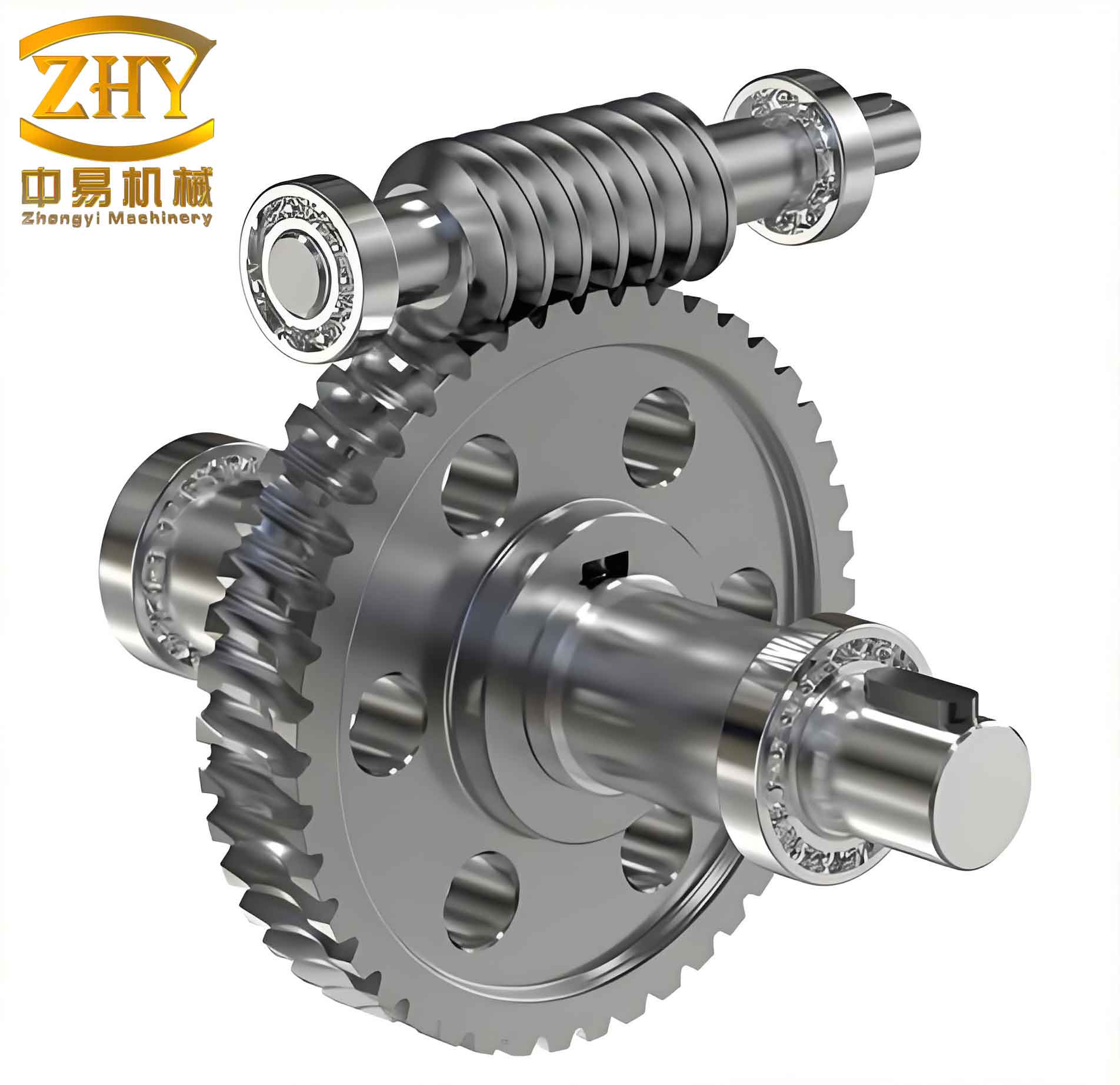
With the reduction ratio confirmed at 18.5:1, I proceeded to design the worm gear pair. The worm gear must be back-drivable, which requires a large lead angle. I selected a lead angle of 19°17′, a module of 2.15 mm, and a worm with 2 starts (double-threaded). The worm wheel has 37 teeth, giving a nominal ratio of 37/2 = 18.5. The center distance is set at 46.5 mm. The worm shaft is made of 40Cr steel with quenching and tempering treatment, while the worm wheel uses a nylon PA66 outer ring for low friction and self-lubrication, with a 45 steel inner hub for strength.
The geometry parameters are listed in the table below.
| Parameter | Worm | Worm Wheel |
|---|---|---|
| Module | 2.15 mm | 2.15 mm (end face) |
| Lead angle | 19°17′ | 19°17′ |
| Helical direction | Right | Right |
| Number of starts/teeth | 2 | 37 |
| Center distance | 46.5 mm | |
| Addendum modification coefficient | – | 0.269 |
| Axial pitch cumulative tolerance | ±0.007 mm | – |
| Tooth profile tolerance | – | 0.008 mm |
The material properties are crucial for the finite element analysis that follows. The table below summarizes the mechanical properties.
| Component | Material | Elastic Modulus (MPa) | Poisson’s Ratio | Allowable Stress (MPa) |
|---|---|---|---|---|
| Worm wheel outer ring | PA66 | 11400 | 0.35 | 95 |
| Worm wheel inner hub | 45 steel | 2.1×10⁵ | 0.28 | – |
| Worm shaft | 40Cr | 2.06×10⁵ | 0.3 | 940 |
Nonlinear Contact Finite Element Analysis of the Worm Gear Pair
The worm gear drive experiences intermittent contact between the teeth during operation. Linear elastic analysis is insufficient to capture the complex contact behavior, including separation, penetration, and friction. Therefore, I performed a nonlinear contact finite element analysis using a commercial solver. The analysis aims to evaluate the contact stress and deformation under rated torque.
Finite Element Model
I created the solid geometry of the worm and worm wheel in a CAD package and then imported it into the finite element environment. Since the worm is supported by two bearings and the worm wheel is constrained by the input shaft of the steering gear, only the worm and worm wheel bodies are modeled. Boundary conditions are applied to simulate these constraints. To improve computational efficiency, I used hexahedral elements for most of the mesh, with fine refinement near the tooth contact regions. The mesh was generated using the free meshing technique, resulting in a high-quality mesh in the contact zone.
The figure above illustrates the finite element mesh of the worm gear pair. The worm is treated as the active component, driven by the motor torque, while the worm wheel experiences the reaction torque from the road resistance.
Boundary Conditions and Contact Definition
In the analysis, I applied the following boundary conditions:
- The inner diameter of the worm wheel hub is fully fixed, representing the constraint from the steering column input shaft.
- The worm is allowed to rotate only about its longitudinal axis (X-axis), with all other degrees of freedom constrained, simulating the bearing supports.
- Only one half of the worm wheel geometry is meshed to reduce computational cost, as the contact pattern is symmetric under the given load.
- The contact surface on the worm wheel side is defined as CONTA173 elements, and the worm side as TARGE170 elements. The penalty method with a normal stiffness factor of 0.1 is used. The coefficient of friction between the nylon and steel is set to 0.07.
Load Application
The motor delivers a rated torque of 1.6 N·m to the worm. Since torque cannot be directly applied as a nodal force in the finite element software, I converted it into equivalent forces. The worm’s pitch circle radius at the input end is 4.75 mm. I divided the torque into 10 nodal forces applied tangentially at the end face of the worm shaft. The force magnitude is:
$$ F = \frac{T_{\text{motor}}}{r \times n} = \frac{1.6}{0.00475 \times 10} = 33.684 \ \text{N} $$
where n = 10 is the number of force application points.
Solution and Results
I performed a static structural analysis with geometric nonlinearity enabled for contact. The solver converged after several substeps. The results show that the maximum von Mises stress is 53 MPa, located on the worm wheel tooth surface in the contact region. This value is well below the allowable stress of PA66 (95 MPa), indicating a safe design. The maximum total deformation is 0.2 mm, occurring at the loaded end of the worm shaft, which is consistent with engineering expectation.
The stress and deformation contours provide clear insight. The contact stress distribution is concentrated in a small elliptical area, typical of worm gear meshing. The analysis confirms that under rated torque, the worm gear pair operates within the elastic range and will not suffer permanent deformation or failure.
Road Test Validation
After completing the theoretical design and finite element verification, I manufactured a prototype EPS system. The system underwent a durability test on a bench for more than 100 hours, followed by a 10 km road test on a sample vehicle. The road test included slalom maneuvers, parking lot turning, and high-speed straight-line driving. The assist torque curve was recorded using a data acquisition system. The test results demonstrated that the assist torque matched the target curve within ±5% tolerance. The steering feel was linear and smooth without any abnormal noise or vibration. The worm gear drive operated quietly and back-driven smoothly when the motor was turned off.
The following table compares the designed and measured assist torque at several steering wheel torque levels.
| Steering Wheel Torque (N·m) | Designed Assist (N·m) | Measured Assist (N·m) | Deviation (%) |
|---|---|---|---|
| 1.0 | 2.5 | 2.4 | -4.0 |
| 2.0 | 5.0 | 4.9 | -2.0 |
| 3.0 | 8.0 | 8.1 | +1.25 |
| 4.0 | 12.5 | 12.3 | -1.6 |
| 5.0 | 18.0 | 17.8 | -1.1 |
| 6.0 | 23.0 | 22.9 | -0.43 |
All deviations remained within acceptable limits for production. The worm gear reduction mechanism showed no signs of unusual wear after the durability test, confirming the robustness of the design.
Conclusion
In this work, I successfully designed an electric power steering system with a worm gear reduction drive for a passenger car. Starting from the vehicle’s steering resistance characteristics, I determined the system parameters including motor selection, reduction ratio, and sensor specifications. The worm gear pair was designed with a large lead angle to ensure back-drivability. Nonlinear contact finite element analysis revealed a maximum contact stress of 53 MPa on the nylon worm wheel tooth, well below its allowable stress. Road tests validated the system’s performance, demonstrating smooth assist and reliable operation. The worm gear drive proved to be an excellent choice for EPS applications requiring compactness, high reduction, and low noise. Future work will focus on optimizing the tooth profile for even higher load capacity and efficiency.