
In my work at a steel plate processing company, I encountered a critical failure in the pusher mechanism’s worm gear reducer. The pusher system uses an electric motor to drive a worm gear reducer, which then drives the driving wheel to push the steel billet into the reheating furnace. The worm gear reducer is the most important component in this transmission system, as it not only transmits power but also bears heavy loads. During a major breakdown, the worm gear drive failed due to severe tooth wear on the worm wheel, with the remaining tooth thickness only about 15% of the original.
1. Transmission Principle of the Pusher Worm Gear Reducer
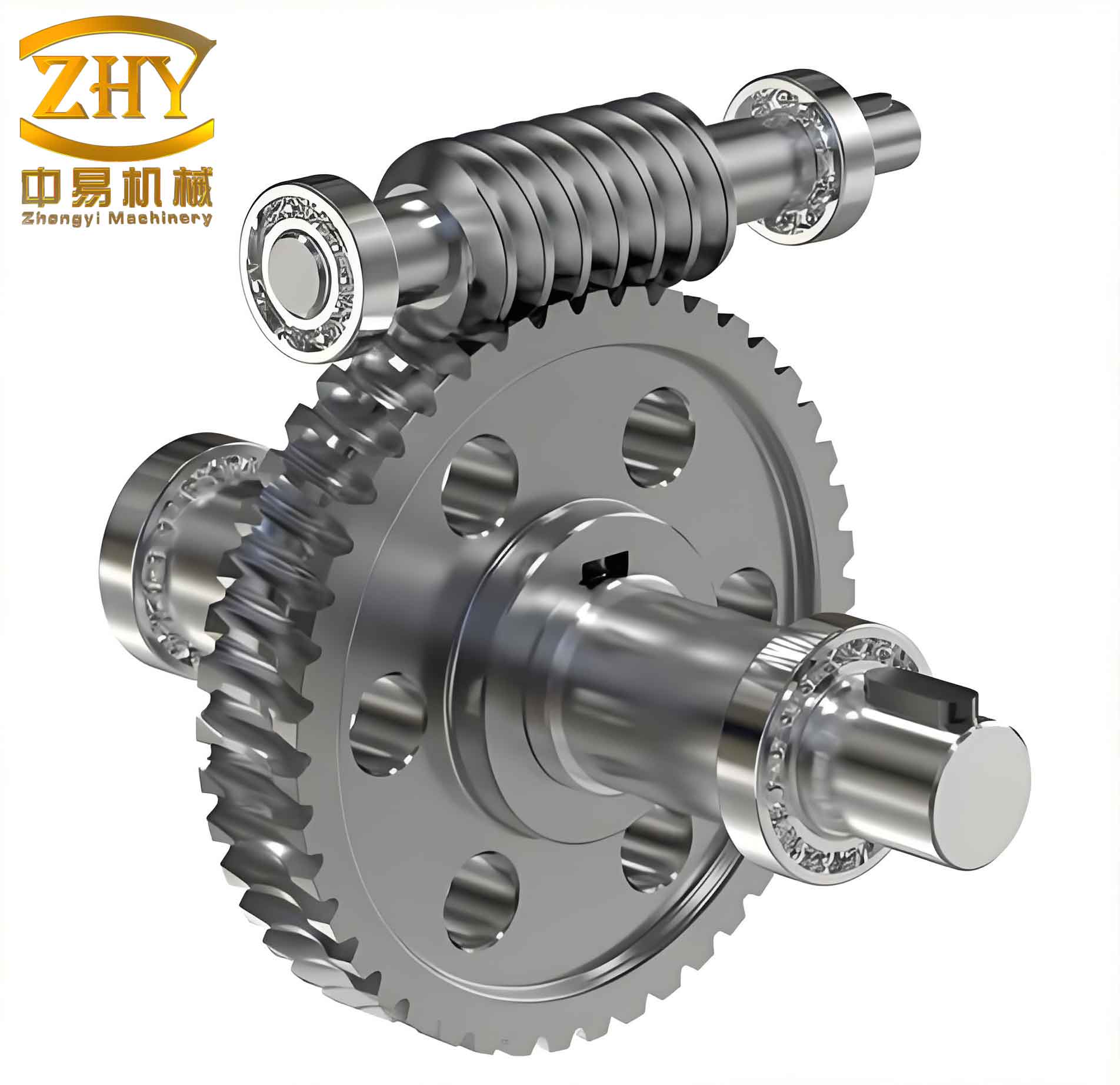
The reducer consists of an input shaft, a double-throated globoidal worm shaft, a worm wheel shaft, and a housing. The transmission principle is as follows: the input shaft’s helical gear drives the mating helical gear on the worm shaft, which then transmits motion to the worm. The worm drives the worm wheel, achieving both power transmission and a reduction ratio of 1:68.
The characteristics of worm gear transmission are:
| Characteristic | Description |
|---|---|
| High reduction ratio | Compact structure, light weight, single-stage ratio up to 1:68 |
| Smooth and quiet operation | Worm thread is continuous, no impact, low noise |
| Self-locking capability | When the lead angle is small, the worm drives the wheel, but not vice versa |
| Low efficiency | Typically 0.7~0.9; self-locking designs are below 0.5 |
| High heat generation | Prone to wear, especially on the worm wheel surface |
2. Failure Modes of Worm Gear Transmission
Due to material and structural differences, the worm thread is generally stronger than the worm wheel teeth. Therefore, failures typically occur on the worm wheel. The main failure modes include: scuffing, pitting, and abrasive wear on the worm wheel tooth surfaces, largely due to high sliding velocity, low efficiency, and significant heat generation.
| Failure Type | Cause | Appearance |
|---|---|---|
| Scuffing | High temperature, rupture of oil film, metal-to-metal contact | Scratches, welding marks on tooth surface |
| Pitting | Cyclic contact stress exceeding fatigue limit | Small pits on tooth surface |
| Abrasive wear | Contaminants in lubricant, inadequate lubrication | Uniform reduction in tooth thickness, burnished appearance |
3. Fault Cause Analysis
In one major worm wheel wear failure, the worm wheel could no longer drive the arm to transmit power. After a detailed investigation, I identified the following root causes.
3.1 Inspection After Opening the Reducer
| Item | Observed Condition |
|---|---|
| Worm wheel teeth | Severely worn, only ~15% of original thickness remained (see Figure 1) |
| Lubricating oil | Contained large amounts of copper powder and impurities |
| Bearings on worm wheel shaft | Both bearings severely worn and damaged; output seal worn and leaking oil |
| Oil scraper | Worn and deformed |
| Worm shaft axial play | Exceeded allowable tolerance |
3.2 Analysis of Failure Causes
1. Bearing failure directly affected the proper meshing of the worm and worm wheel. The lubrication oil contained many impurities, reducing its film-forming capability, thus increasing wear. Excessive load and frequent starts aggravated the wear.
2. Reasons for bearing damage: Improper adjustment during assembly (excessive axial play), uneven tightening of bearing cap bolts, and inadequate lubrication. The oil scraper failed to direct oil to the bearings, causing a temperature rise, reduced material hardness, and eventual bearing seizure.
3. Oil scraper deformation: The original copper scraper only contacted the side face of the worm wheel lightly. When the worm wheel shaft had excessive axial play (>2 mm), the wheel shifted sideways during load, deforming the scraper and blocking oil flow to the bearings.
4. Material mismatch: The worm is made of hardened steel (high wear resistance), while the worm wheel is made of cast aluminum bronze (softer). Thus, all wear concentrated on the worm wheel.
4. Fault Remediation and Preventive Measures
Based on the analysis, I implemented the following corrective actions.
4.1 Replacement and Assembly Procedure
Replace the worm and worm wheel as a matched set to ensure proper meshing accuracy and contact pattern.
| Step | Action | Key Parameter / Tolerance |
|---|---|---|
| 1 | Thoroughly clean the housing and all components | Remove all debris, old lubricant |
| 2 | Pre-lubricate bearings with grease before assembly | Avoid dry running |
| 3 | Measure bearing clearance using lead wire method for worm shaft | Add 0.05~0.1 mm additional clearance; use selected shims |
| 4 | Assemble worm with 2 mm shim between bearing and housing face; adjust axial position | Globoidal worm requires precise axial location |
| 5 | Manually rotate input shaft; ensure smooth rotation with no binding | Check for jamming |
| 6 | Install worm wheel; lower slowly using hoist to avoid impact | Prevent plastic deformation |
| 7 | Adjust worm wheel shaft bearing clearance using lead wire; target axial play | 0.05~0.1 mm |
| 8 | Apply Prussian blue to worm wheel teeth; rotate manually to check contact pattern | Contact pattern should be central, slightly toward exit side; area ≥ 60% |
4.2 Adjustment of Contact Pattern
During the spotting test, if the contact pattern is biased to one side, adjust the worm wheel shaft axial position by transferring shims from one side to the other. If the pattern is biased toward the tooth root, adjust the worm shaft axial position. The final contact pattern should be located near the pitch line, uniform, and slightly toward the exit side.
The acceptable contact area is defined as:
$$ \text{Contact Area Ratio} = \frac{\text{Measured contact area}}{\text{Total tooth flank area}} \ge 60\% $$
4.3 Checking Backlash
After assembly, check the meshing backlash by rotating the input shaft while holding the worm wheel stationary. The angular rotation of the worm corresponds to the circumferential backlash. Excessive backlash causes noise and impact; too little causes overheating and seizure. The acceptable range:
$$ j_n = \frac{\pi \cdot m_x \cdot \Delta \theta}{360^\circ} $$
where:
- $j_n$ = normal backlash (mm)
- $m_x$ = axial module of worm (mm)
- $\Delta \theta$ = worm rotation angle (degrees) when worm wheel is locked
| Parameter | Typical Value |
|---|---|
| Backlash (normal) | 0.10 ~ 0.25 mm for moderate size reducers |
| Worm rotation angle for free movement | Should not exceed 3°~5° at input |
4.4 Lubrication and Scraper Modification
Use extreme-pressure (EP) worm gear oil N460. Fill to the specified level on the dipstick. The original copper scraper was replaced with a thin steel plate bent at a specific angle, providing a preload against the worm wheel side face to ensure reliable oil flow into the bearing grooves.
4.5 Improvement in Manufacturing
Request the manufacturer to reduce the surface roughness of the worm wheel teeth to $R_a \le 0.8\ \mu m$ to improve lubrication film formation.
5. Routine Maintenance and Inspection
To prevent recurrence, I established the following daily/weekly inspection checklist:
| No. | Inspection Item | Method / Criterion |
|---|---|---|
| 1 | Axial play of input shaft, worm shaft, worm wheel shaft under dynamic condition | Use dial indicator; should be within 0.05~0.15 mm |
| 2 | Oil level and oil cleanliness | Check dipstick; take oil sample for particle analysis |
| 3 | Worm wheel wear condition | Listen for abnormal noise; measure tooth thickness periodically |
| 4 | Housing temperature | Infrared thermometer; oil temperature ≤ 80°C |
| 5 | Seal leakage | Visual check; no oil dripping |
| 6 | Bolt tightness on bearing caps | Torque wrench; ensure uniform preload |
5.1 Run-in Test Procedure
After assembly, conduct a continuous operation test:
- Run at rated speed and 50% load for 2 hours in forward direction.
- Then run in reverse direction for 2 hours.
- Monitor oil temperature rise; must stay below 80°C.
- Check all seals for leakage.
- After initial test, drain the oil, flush the housing, and refill with fresh N460 oil.
- Run full-load test for another 2 hours.
The allowable temperature rise can be estimated by:
$$ \Delta T = \frac{P(1-\eta)}{C_p \cdot \dot{m}} $$
where:
- $P$ = input power (kW)
- $\eta$ = transmission efficiency (typically 0.7~0.9)
- $C_p$ = specific heat of oil (kJ/kg·K)
- $\dot{m}$ = oil mass flow rate (kg/s) through cooler (if any)
6. Five Technical Requirements for Worm Gear Assembly
To ensure long-term reliability, all five requirements must be met:
| Requirement | How to Achieve |
|---|---|
| 1. Worm axis ⟂ worm wheel axis | Ensured by machining of housing; verify with square and feeler gauge |
| 2. Worm axis in symmetry plane of worm wheel | Adjust worm wheel axial position using shims |
| 3. Center distance accuracy | Machined housing; measured with pin gauges; tolerance ±0.05 mm |
| 4. Proper backlash | Check by rotating worm; adjust shims or select different center distance |
| 5. Correct contact pattern | Spotting test; pattern at pitch line, area ≥ 60%, slightly toward exit side |
7. Conclusion
After implementing the above corrective measures, the pusher worm gear reducer operated reliably with improved tooth contact, reduced wear, and extended service life. The key lessons learned are:
- The worm gear reducer requires precise assembly, especially for the globoidal worm.
- Bearing condition directly dictates worm gear meshing quality; proper lubrication and axial play control are critical.
- The oil scraper design must be robust enough to withstand axial shifting of the worm wheel.
- Routine oil analysis and temperature monitoring can provide early warning of wear progression.
By following the five technical requirements for worm gear assembly and the preventive maintenance schedule, the pusher system now operates with minimal downtime, ensuring smooth production in the steel mill.