
The pursuit of high-performance power transmission has consistently driven advancements in gear technology. Among various gear types, hypoid gears stand out due to their unique capabilities. The offset arrangement of their axes allows for a higher gear ratio, increased contact ratio, greater load-bearing capacity, smoother operation, and improved efficiency within a compact design. These attributes make hypoid gears indispensable in critical applications across the aerospace, automotive, and heavy machinery industries. The meshing performance of a hypoid gear pair is most intuitively evaluated through two key indicators: the tooth contact pattern (TCP) and the transmission error (TE) curve. An optimal, stable, and well-centered contact pattern under load, coupled with minimal transmission error, is paramount for ensuring quiet operation, longevity, and reliability. However, achieving this ideal performance, particularly for hyperboloidal gears manufactured by the “Completing Method” or Duplex Helical Method, presents a significant challenge. A persistent issue is the difficulty in synchronously adjusting the contact characteristics on both the drive (working) and coast (non-working) flanks, which can lead to suboptimal performance in real-world operating conditions.
The Duplex Helical Method differentiates itself from traditional multi-cut methods (like the “five-cut” method) by introducing a specific machining motion parameter known as the helical motion coefficient. During the generation process, the cutter head performs an additional feed motion along the cradle axis, causing a continuous, time-dependent change in the sliding base setting. This controlled motion provides a powerful tool for pre-adjusting the tooth surface topology and, consequently, the contact characteristics. Despite its potential, the widespread industrial application of the full generating method for hyperboloidal gears requires deeper theoretical understanding and predictive modeling capabilities.
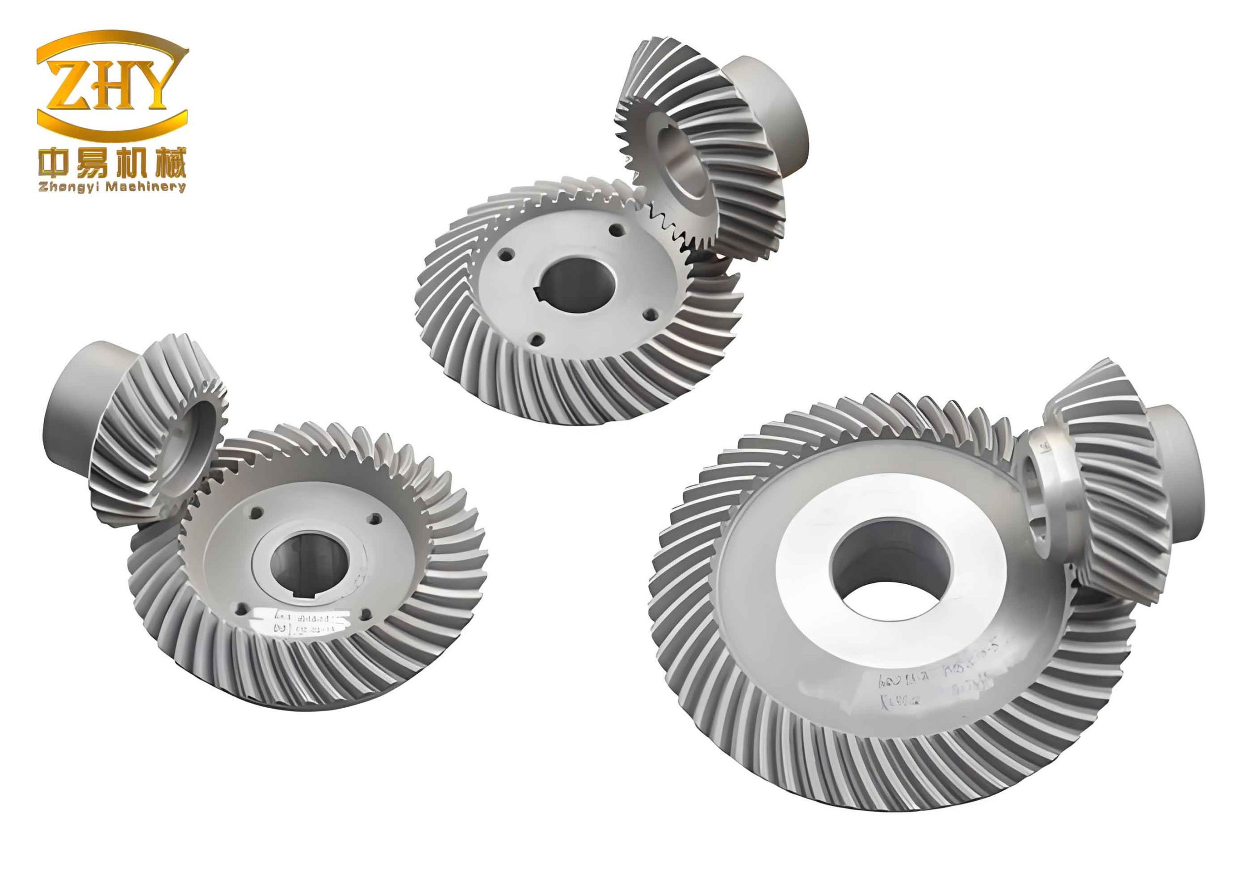
Extensive research has been conducted globally on the meshing theory of spiral bevel and hyperboloidal gears. Foundational work established mathematical models for gear design and manufacturing. Subsequent studies have delved into the cutting principles of the full generating method, developed new calculation formulas for machine tool settings, and analyzed the influence of various adjustment parameters on meshing performance. A significant area of focus is the sensitivity of gear pairs to assembly misalignments—such as changes in pinion axial distance (mounting distance), offset, gear mounting distance, and shaft angle—and the development of robust design methodologies to mitigate these effects. Beyond traditional Tooth Contact Analysis (TCA), the concept of ease-off (or tooth surface mismatch topology) has gained considerable importance. Ease-off analysis provides a comprehensive, three-dimensional map of the deviation between conjugate and actual tooth surfaces, offering deeper insights into contact mechanics and guiding advanced surface modification strategies. Research has explored using modified cutter profiles, Free-Form machine capabilities, and sophisticated optimization algorithms based on ease-off to achieve superior meshing performance, avoid edge contact, and reduce contact stresses. Building upon this substantial body of work, this article employs advanced numerical analysis and tooth surface topology tools to investigate the meshing performance of hyperboloidal gears manufactured by the Duplex Helical Method. By developing a TCA program through FORTRAN and MATLAB hybrid programming, this study aims to elucidate the relationship between the helical motion coefficient and the geometric morphology of the pinion tooth surface, as well as the position of generating lines. Furthermore, it analyzes the contact characteristics of both flanks under various installation errors, providing a theoretical foundation for the high-quality and efficient manufacturing of hyperboloidal gear pairs.
Mathematical Model for Hypoid Gears via the Duplex Helical Method
Mathematical Model for the Generating Surface of the Pinion’s Straight-Bladed Cutter
The manufacturing process begins with defining the cutter. For the pinion, a straight-bladed cutter profile is typically used. A coordinate system $S_0 \{X_0, Y_0, Z_0\}$ is fixed to the cutter head, with the cutter axis $c_0$ aligned with the $Z_0$ axis. The straight-blade profile consists of two main sections: the primary straight section (a) and a circular tip section (b) for generating the fillet. Key parameters include the fillet radius $\rho_1$, the cutter profile angle $\alpha_{01}$, the nominal cutter radius $r_{01}$, the blade edge width $p_{w1}$, the tip radius $r_{c1}$, and the profile parameters $s_1$ and $\lambda_1$ for sections a and b, respectively. $\theta_1$ is the rotation angle of the cutter. The relationship $r_{c1} = r_{01} \pm 0.5p_{w1}$ holds, where the sign depends on the side being cut.
The position vector and unit normal vector for the generating surface of the straight section (a) of the pinion cutter, expressed in the cutter coordinate system $S_0$, are given by:
$$
\mathbf{r}_{01} = \begin{bmatrix}
(-r_{c1} \pm s_1 \sin\alpha_{01}) \sin\theta_1 \\
(-r_{c1} \pm s_1 \sin\alpha_{01}) \cos\theta_1 \\
s_1 \cos\alpha_{01}
\end{bmatrix}
$$
$$
\mathbf{n}_{01} = \begin{bmatrix}
-\cos\alpha_{01} \sin\theta_1 \\
-\cos\alpha_{01} \cos\theta_1 \\
\mp \sin\alpha_{01}
\end{bmatrix}
$$
In these equations, the upper sign corresponds to the concave side (drive side) and the lower sign to the convex side (coast side) of the hyperboloidal gears.
Mathematical Model for the Pinion Tooth Surface
The generation of the pinion tooth surface involves a series of coordinate transformations from the cutter to the workpiece. A machine coordinate system $S_m \{X_m, Y_m, Z_m\}$ is rigidly connected to the machine. The cradle rotates about the $Z_m$ axis. The unit vector along the pinion axis is denoted as $\mathbf{p}_1$, and the unit vector along the generating gear axis is $\mathbf{g}_1$. The plane $X_mO_mY_m$ is the machine plane, with $O_m$ as the machine center, $O_0$ as the cutter center, and $O_1$ as the pinion crossing point.
The generating surface equation and its unit normal are transformed into the machine coordinate system $S_m$:
$$
\mathbf{r}_{m01} = \mathbf{R}[z, -q] \left\{ \mathbf{R}[z, J_1] \mathbf{R}[x, I_1] \mathbf{r}_{01} + [S_{r1}, 0, 0]^T \right\}
$$
$$
\mathbf{n}_{m01} = \mathbf{R}[z, -q] \mathbf{R}[z, J_1] \mathbf{R}[x, I_1] \mathbf{n}_{01}
$$
Here, $q = q_1 + \Delta q_1$, where $q_1$ is the initial rotational position of the cradle, and $\Delta q_1$ is its incremental rotation. $\mathbf{R}[z, -q]$ denotes the rotation matrix about the z-axis by angle $-q$.
A defining feature of the Duplex Helical Method is the helical motion. The sliding base setting $X_B$ is not constant but varies linearly with the cradle rotation:
$$
X_B = X_{B1} – H_{l1} \Delta q_1
$$
where $H_{l1}$ is the helical motion coefficient, a key parameter for controlling the tooth surface topography of hyperboloidal gears.
Subsequently, the position vector from the pinion crossing point $O_1$ to the machine center $O_m$, denoted $\mathbf{m}_1$, along with the relative angular velocity $\boldsymbol{\omega}_{p1}$ and relative velocity $\mathbf{v}_{p1}$ between the generating gear and the workpiece, are substituted into the equation of meshing. Solving this system yields the mathematical definition of the pinion tooth surface and its unit normal in its own coordinate system:
$$
\begin{cases}
\mathbf{r}_1 = \mathbf{r}_{m01} + \mathbf{m}_1 \\
\mathbf{n}_1 = \mathbf{n}_{m01}
\end{cases}
$$
Assembly Model for the Hypoid Gear Pair
To perform Tooth Contact Analysis (TCA) and construct ease-off topography maps, the tooth surfaces must be discretized. A grid of points is defined across the active tooth flank in the lengthwise and profile directions. For a point $M$ on the pinion surface with position vector $\mathbf{r}_1$, its radial distance from the pinion axis and its projection along the axis relative to the crossing point are calculated as:
$$
\begin{cases}
r_1 = |\mathbf{r}_1 \times \mathbf{p}_1| \\
L_1 = -\mathbf{r}_1 \cdot \mathbf{p}_1
\end{cases}
$$
Using the calculated discrete points in DAT format, a three-dimensional assembly model of the hyperboloidal gear pair can be constructed in CAD software (e.g., UG NX), following a process from point cloud to surface to solid model to final assembly. The basic geometric parameters for an example hypoid gear pair (7×43) are summarized in the table below.
| Parameter | Pinion | Gear |
|---|---|---|
| Number of Teeth | 7 | 43 |
| Module (mm) | 6.860 | 6.860 |
| Face Width (mm) | 43.51 | 40.00 |
| Offset (mm) | 25.40 | |
| Shaft Angle (°) | 90 | |
| Spiral Angle (°) | 50.03 | 38.80 |
| Mean Cone Distance (mm) | 129.99 | 130.44 |
| Hand of Spiral | LH | RH |
The corresponding machine settings for manufacturing this pair via the Duplex Helical Method are critical and include parameters such as cutter diameter, blade angles, radial setting, machine root angle, and the helical motion coefficient $H_{l1}$.
Analysis of Meshing Performance for Hyperboloidal Gears
Influence of the Helical Motion Coefficient on Contact Characteristics and Geometric Topography
Traditional methods often produce a contact path that is nearly straight and perpendicular to the root line, which is frequently inadequate for modern performance demands. The introduction of the helical motion in the Duplex Helical Method is a pivotal advancement for hyperboloidal gears. It enables pre-control over the diagonal orientation and length of the contact path, thereby influencing the overlap ratio and allowing for precise tailoring of the tooth contact pattern to enhance meshing performance. This section investigates the effect of varying the helical motion coefficient while keeping all other machine settings constant.
To quantitatively study the effect on tooth surface geometry, an ease-off (mismatch) topography map is constructed. The principle involves calculating a reference tooth surface (generated with a base helical coefficient $H_{l1}$) and comparison surfaces (generated with modified $H_{l1}^{k}$). Both surfaces are discretized into a grid of points. For each corresponding grid point $(i, j)$, the mismatch $m^{k}_{ij}$ is defined as the projection of the vector difference between the comparison surface point $\mathbf{r}^{k}_{ij}$ and the reference surface point $\mathbf{r}^{1}_{ij}$ onto the unit normal $\mathbf{n}^{1}_{ij}$ of the reference surface:
$$
m^{k}_{ij} = (\mathbf{r}^{k}_{ij} – \mathbf{r}^{1}_{ij}) \cdot \mathbf{n}^{1}_{ij}
$$
Plotting $m^{k}_{ij}$ across the grid creates a three-dimensional ease-off map, visually representing the modification induced by changing $H_{l1}$. The analysis cases are defined as follows:
| Case | Change in $H_{l1}$ (mm/rad) | $H_{l1}$ Value (mm/rad) |
|---|---|---|
| 1 (Reference) | 0 | -1.4754 |
| 2 | -0.5 | -1.9754 |
| 3 | +0.5 | -0.9754 |
| 4 | -1.0 | -2.4754 |
| 5 | +1.0 | -0.4754 |
The TCA results for these cases reveal clear trends. The helical motion coefficient significantly affects the contact pattern location and geometry for hyperboloidal gears. As $H_{l1}$ increases (becomes less negative), the contact path on the working flank lengthens and its diagonal angle increases. Conversely, decreasing $H_{l1}$ shortens the path and reduces its angle. The maximum transmission error (TE) magnitude is also influenced, showing different sensitivities on the working and non-working flanks. The TE on the working flank generally decreases as $H_{l1}$ increases.
The ease-off analysis provides profound insight into the modification principle. The helical motion applies a diagonal crowning to the pinion tooth surface. Crucially, the direction of this crowning is opposite for the two flanks of the hyperboloidal gears:
- Working Flank (Concave): The modification progresses from the toe-root to the heel-top.
- Non-Working Flank (Convex): The modification progresses from the heel-root to the toe-top.
The magnitude of modification is also asymmetric. On the working flank, the modification at the toe is generally larger than at the heel. On the non-working flank, the modification at the heel is generally larger than at the toe. This fundamental understanding is key to pre-contacting the performance of hyperboloidal gears machined by the Duplex Helical Method.
Influence of the Helical Motion Coefficient on Generating Line Position
In the grinding process, the tooth surface is composed of a series of micro-surfaces left by the moving cutter blade. The path traced by a specific point on the cutter blade, known as the generating line, directly influences the microscopic topography of the tooth surface. Therefore, understanding how machine parameters affect generating line position is important for controlling the final quality of hyperboloidal gears. The position of a generating line on the tooth surface is primarily governed by the blade profile parameter $s_1$. By establishing the relationship between the surface coordinates $(x_i, y_i)$ and $s_1$, typically a polynomial function $y_i = f(s_1)$, one can determine the locus of points on the surface corresponding to a constant $s_1$ value, which defines a generating line.
By analyzing generating lines for different constant $s_1$ values (e.g., $s_1 = 2, 4, 6, 8$ mm) across the cases with varying helical motion coefficients, distinct patterns emerge for hyperboloidal gears. The generating lines shift systematically with $H_{l1}$. On the working flank, as $H_{l1}$ increases, generating lines near the heel move towards the root, and lines near the toe move towards the tip. On the non-working flank, the opposite occurs: as $H_{l1}$ increases, generating lines near the heel move towards the tip, and lines near the toe move towards the root. This behavior is consistent with the diagonal crowning effect revealed by the ease-off analysis and further elucidates the kinematic mechanism behind the surface modification in the Duplex Helical Method.
Influence of Assembly Errors on Meshing Performance of Hyperboloidal Gears
In practice, perfect assembly is unattainable. Misalignments such as incorrect pinion mounting distance ($\Delta H$), pinion offset error ($\Delta V$), gear mounting distance error ($\Delta J$), and shaft angle error ($\Delta \Sigma$) are inevitable. For locally conjugate gear pairs like hyperboloidal gears, these errors cause the contact pattern to shift and distort, potentially leading to edge contact, increased noise, and reduced load capacity. Analyzing sensitivity to these errors is crucial for robust design and setting acceptable assembly tolerances. The actual assembly positions are defined as:
$$
\begin{cases}
H’ = H + \Delta H \\
V’ = V + \Delta V \\
J’ = J + \Delta J \\
\Sigma’ = \Sigma + \Delta \Sigma
\end{cases}
$$
A systematic TCA study was conducted by varying each error within a realistic range while holding others at zero. The effects on the contact pattern location, shape, and maximum TE for both flanks of the hyperboloidal gears are summarized below.
| Error Type | Change | Effect on Working Flank Contact Path | Effect on Non-Working Flank Contact Path | Effect on Max TE (Working/Non-Working) |
|---|---|---|---|---|
| Pinion Mounting Distance ($\Delta H$) | Increase | Shifts towards Toe and Tip | Shifts towards Heel and Tip | Increases / Decreases |
| Decrease | Shifts towards Heel and Root | Shifts towards Toe and Root | Decreases / Increases | |
| Pinion Offset ($\Delta V$) | Increase | Shifts towards Toe and Tip | Shifts towards Heel and Tip | Decreases / Increases |
| Decrease | Shifts towards Heel and Root | Shifts towards Toe and Root | Increases / Decreases | |
| Gear Mounting Distance ($\Delta J$) | Increase | Shifts towards Heel and Root | Shifts towards Heel and Root | Increases / Increases |
| Decrease | Shifts towards Toe and Tip | Shifts towards Toe and Tip | Decreases / Decreases | |
| Shaft Angle ($\Delta \Sigma$) | Increase | Lengthens, Diagonal Angle Increases | Lengthens, Diagonal Angle Increases | Increases / Increases |
| Decrease | Shortens, Diagonal Angle Decreases | Shortens, Diagonal Angle Decreases | Decreases / Decreases |
This analysis provides a clear map of how each assembly error influences the sensitive meshing behavior of hyperboloidal gears. The non-working flank often shows different or more pronounced sensitivity compared to the working flank, highlighting the importance of analyzing both sides for a comprehensive assessment of gear pair robustness.
Experimental Validation: Gear Grinding and Rolling Test
To validate the correctness of the developed mathematical model and the predicted influence of the helical motion, the example 7×43 hypoid gear pair was manufactured. The pinion was ground on a modern CNC hypoid gear grinding machine (e.g., H350G) using the calculated machine settings, including the specified helical motion coefficient $H_{l1}$. Subsequently, the gear pair was assembled on a rolling test machine under a light load (e.g., 20 Nm) and run at a specified speed (e.g., 1440 rpm). The observed contact patterns on both the drive and coast sides were recorded.
The experimental contact patterns showed a well-centered, diagonal orientation located in the mid-region of the tooth flank. The shape, location, and diagonal direction closely matched the results predicted by the numerical Tooth Contact Analysis (TCA). This strong correlation between the theoretical simulation and physical experiment confirms the accuracy of the established mathematical model for the tooth surface generation and assembly of hyperboloidal gears. Furthermore, it successfully demonstrates the practical efficacy of the helical motion coefficient in the Duplex Helical Method as a powerful parameter for pre-contacting the contact pattern characteristics—specifically its diagonal orientation and length—in the manufacturing of high-performance hyperboloidal gears.
Conclusions
This comprehensive study on hyperboloidal gears manufactured by the Duplex Helical Method leads to the following key conclusions:
- Modeling and Error Sensitivity: A precise mathematical model for tooth surface generation and gear pair assembly was established. Using Tooth Contact Analysis (TCA), the effects of critical assembly errors (pinion mounting distance $\Delta H$, offset $\Delta V$, gear mounting distance $\Delta J$, and shaft angle $\Delta \Sigma$) on the contact pattern and transmission error of hyperboloidal gears were systematically quantified, providing essential data for tolerance analysis and robust design.
- Helical Motion Coefficient and Surface Topography: The helical motion coefficient ($H_{l1$) is a fundamental control parameter in the Duplex Helical Method. TCA results confirm that varying $H_{l1$ directly controls the length and diagonal angle of the contact path. More importantly, through ease-off (tooth surface mismatch) analysis, it was revealed that $H_{l1$ introduces a diagonal crowning modification. The direction of this crowning is opposite for the working and non-working flanks of hyperboloidal gears, explaining the method’s unique capability for independent flank adjustment.
- Generating Line Analysis: By establishing the relationship between the cutter profile parameter and tooth surface coordinates, the concept of generating lines was analyzed. The study demonstrated that the helical motion coefficient systematically shifts the position of these generating lines across the tooth flank, providing a kinematic perspective on how the surface modification is physically achieved during the cutting/grinding of hyperboloidal gears.
- Experimental Verification: The manufacturing and rolling test of a hypoid gear pair produced contact patterns that were in excellent agreement with the numerical predictions. This experimental validation confirms the correctness of the developed mathematical models and substantiates the practical utility of the helical motion for pre-contacting the meshing performance of hyperboloidal gears, paving the way for its more widespread and effective industrial application.
In summary, this work integrates advanced numerical modeling, topological analysis, and experimental validation to deepen the understanding of the Duplex Helical Method for hyperboloidal gears. The insights gained into the relationship between the helical motion coefficient, tooth surface geometry, and meshing performance under misalignment provide a solid foundation for the high-precision design, manufacturing, and quality assurance of these critical power transmission components.