
This research presents a comprehensive study on the integrated design and manufacturing of a straight spur gear using the Pro/E platform. By leveraging the secondary development tool Pro/Toolkit within the Visual C++ 6.0 environment, we have developed a parametric modeling system that automatically generates NC code for the straight spur gear. The work emphasizes the parameterization process, interactive interface design, and automatic NC code generation, providing a valuable reference for achieving CAD/CAM integration and automation of complex mechanical components. Throughout this paper, the straight spur gear serves as the primary example to illustrate the methodology and implementation details.
1. Introduction
Virtual manufacturing technology integrates computer simulation, modeling, computer graphics, artificial intelligence, concurrent engineering, and multimedia technologies into a comprehensive system. During the product design phase, modeling and simulation technologies enable rapid simulation of future manufacturing processes, prediction and evaluation of product performance and manufacturability, thereby organizing production more efficiently, economically, and flexibly. The ultimate goals are to minimize product development cycles and costs, optimize product design quality, and maximize production efficiency. As a key technology in virtual manufacturing, three-dimensional modeling and machining simulation are particularly important.
Pro/ENGINEER (Pro/E) is a widely used 3D CAD/CAM/CAE software. It not only possesses powerful 3D modeling capabilities but also includes the Pro/NC module, which allows simulation machining of parts and automatic generation of required NC codes through appropriate post-processors. This capability is especially beneficial for solving the NC programming challenges of complex parts. In this study, we focus on the straight spur gear and achieve parametric design and automatic NC code generation, thereby making a meaningful exploration toward the integration of design and manufacturing.
2. Parametric Modeling of the Straight Spur Gear
The parametric modeling of the straight spur gear is the foundation of the entire CAD/CAM integration. We employed the Program modeling method within the Pro/E environment to create the initial part model. Accurate 3D tooth profile modeling is essential. Using the Tools/Parameters and Tools/Relations options in the main menu, we precisely defined the gear parameters and relations.
2.1 Parameter Definition
First, we entered the part design interface of Pro/E and clicked Tools → Parameters to open the parameter dialog box. The following parameters were added for the straight spur gear:
| Parameter | Symbol | Description |
|---|---|---|
| Module | \( m \) | Module of the gear |
| Number of teeth | \( z \) | Number of teeth |
| Pressure angle | \( \alpha \) | Standard pressure angle (usually 20°) |
| Tooth thickness | \( B \) | Face width of the gear |
| Addendum | \( h_a \) | Height of tooth above pitch circle |
| Dedendum | \( h_f \) | Depth of tooth below pitch circle |
| Addendum coefficient | \( h_{ax} \) | Standard value (typically 1.0) |
| Clearance coefficient | \( c_x \) | Standard value (typically 0.25) |
| Profile shift coefficient | \( x \) | Correction coefficient (zero for standard gears) |
2.2 Relationship Equations
After defining the parameters, we added the following relationship equations in the Relations dialog box to compute geometric dimensions automatically:
\[
\begin{aligned}
h_a &= m (h_{ax} + x) \\
h_f &= m (h_{ax} + c_x – x) \\
d &= m \cdot z \\
d_a &= d + 2h_a \\
d_b &= d \cos \alpha \\
d_f &= d – 2h_f
\end{aligned}
\]
Here, \( d \) is the pitch circle diameter, \( d_a \) is the addendum circle diameter, \( d_b \) is the base circle diameter, and \( d_f \) is the dedendum circle diameter. These equations ensure that any change in the input parameters automatically updates the entire geometry of the straight spur gear.
2.3 Tooth Profile Generation
To create the involute tooth profile, we used the Curve → From Equation option. In a cylindrical coordinate system, the involute curve equations are given by:
\[
\begin{aligned}
r &= \frac{d_b}{2 \cos \theta} \\
\theta &= t \cdot \sqrt{\left(\frac{d_a}{d_b}\right)^2 – 1} \quad \text{(parameter } t \text{ from 0 to 1)} \\
z &= 0
\end{aligned}
\]
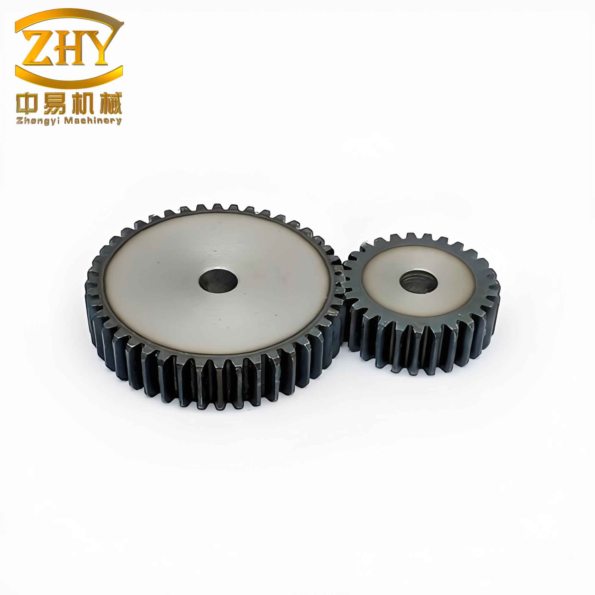
After generating the involute curve, we mirrored it to obtain the symmetrical tooth flank. Then, we sketched the tooth profile and performed an extrusion to create the first tooth. Using the Copy and Rotate feature operation, we created the second tooth and then patterned it to generate all teeth of the straight spur gear. For the example presented, we used the following given parameters: \( z = 17 \), \( \alpha = 20^\circ \), \( m = 1.5 \) mm, and \( B = 10 \) mm. The resulting parametric model of the straight spur gear is illustrated below.
3. Interactive Interface Design for Parametric Control
To allow users to easily modify the parameters of the straight spur gear without manually entering the Pro/E internal environment, we developed an interactive interface using Pro/Toolkit and Microsoft Foundation Classes (MFC) in Visual C++ 6.0. The interface includes menu customization and dialog box design.
3.1 Menu Creation
We added a new menu bar called “GEAR” to the Pro/E main menu using the function ProMenubarMenuAdd(). The relevant code snippet is as follows:
status = ProMenubarMenuAdd("GEAR", "GEAR", "Utilities", PRO_B_TRUE, MsgFile);
Then, we used ProCmdActionAdd() to define the actions when the menu items are clicked:
status = ProCmdActionAdd("Enter CAD Model", (uiCmdCmdActFn)test1, uiCmdPriDefault, UsrAccessDefault, PRO_B_TRUE, PRO_B_TRUE, &test1);
status = ProCmdActionAdd("Enter NC Machining", (uiCmdCmdActFn)test2, uiCmdPriDefault, UsrAccessDefault, PRO_B_TRUE, PRO_B_TRUE, &test2);
Finally, we added push buttons to the menu using ProMenubarmenuPushbuttonAdd():
status = ProMenubarmenuPushbuttonAdd("GEAR", "CAD_model", "CAD_model", "CAD_model", NULL, PRO_B_TRUE, test1, MsgFile);
status = ProMenubarmenuPushbuttonAdd("GEAR", "NC_machining", "NC_machining", "NC_machining", NULL, PRO_B_TRUE, test2, MsgFile);
This creates a drop-down menu with two options: one for entering the parametric CAD model interface and another for entering the NC machining module.
3.2 Model Retrieval and Dialog Design
First, we used Pro/Toolkit functions to retrieve all design parameters from the 3D model of the straight spur gear that were previously defined in the Parameters dialog. Next, we developed a dialog application using MFC. The dialog contains edit boxes corresponding to each parameter (module, number of teeth, pressure angle, face width, profile shift coefficient, etc.) and buttons for “Regenerate” and “Close”. When the user modifies any parameter value and clicks “Regenerate”, the program updates the corresponding Pro/E model and regenerates the geometry automatically. The designed dialog for the straight spur gear parameter setting is shown schematically in the table below.
| Control Type | Variable | Label |
|---|---|---|
| Edit Box | m_Module | Module (m) |
| Edit Box | m_Teeth | Number of Teeth (z) |
| Edit Box | m_PressureAngle | Pressure Angle (α) |
| Edit Box | m_FaceWidth | Face Width (B) |
| Edit Box | m_ProfileShift | Profile Shift Coefficient (x) |
| Button | Regenerate | Regenerate Model |
| Button | Close | Close Dialog |
This interactive approach significantly simplifies the modification process for the straight spur gear, enabling non-expert users to quickly generate new designs by simply entering desired parameters.
4. CNC Machining Module for the Straight Spur Gear
The ultimate goal of CAD/CAM integration is to automatically generate manufacturing instructions. Using the Pro/NC module, we simulated the machining process of the straight spur gear and generated the corresponding NC code. The procedure mimics real manufacturing operations, including tool path calculation, simulation, and post-processing.
4.1 Pro/NC Machining Workflow
The overall Pro/NC machining process for the straight spur gear follows these steps:
- Create the reference model (the designed gear) and the workpiece model (raw block).
- Set up the machine tool and cutting tools. Define the machine coordinate system.
- Define NC sequences (operations) such as face milling, contour profile milling, and local contour milling.
- Simulate the tool path to verify correctness.
- Post-process the CL (cutter location) data file to generate the final NC program.
For the straight spur gear, we adopted a multi-step milling strategy: face milling to flatten the top surface, contour profile milling to cut the tooth spaces, and local contour milling to finish the tooth flanks. The tool path trajectories for face milling and local contour milling are representative.
4.2 Tool Path Generation
After configuring all machining parameters in Pro/NC, the system generates a CL data file (ASCII format). This file contains the coordinates and orientation of the tool center along the path. However, this file cannot directly drive a CNC machine; it must be translated into a specific machine-readable format. This translation is performed by a post-processor.
Pro/E includes a post-processing module called NC Post that converts the CL file into a .tap file (or other formats) containing G-code and M-code instructions. The post-processor interprets the generic tool path data according to the specific kinematics and syntax of the target CNC controller.
4.3 Automatic NC Code Generation via Secondary Development
To fully automate the NC code generation for the straight spur gear, we utilized Pro/Toolkit and Visual C++ to create a dynamic link library (DLL) that integrates with Pro/E. This DLL loads as a custom menu within the Pro/E environment. The program reads the machining parameters (such as tool selection, cutting speed, feed rate, stepover, and depth of cut) from a database or user input through the dialog interface. It then automatically triggers the Pro/NC sequence generation and post-processing without manual intervention.
The key functions used in the secondary development include:
ProMdlCurrentGet()to get the current model handleProParameterInit()to access design parametersProUtilFileCopy()to copy template NC filesProMenuActionAdd()to integrate the new command
The generated post-processed NC program for the straight spur gear (partial listing) is illustrated in Table 3.
| Line | Code | Description |
|---|---|---|
| N10 | G90 G17 G40 G80 | Absolute positioning, XY plane, cancel cutter compensation, cancel canned cycles |
| N20 | G21 | Metric units |
| N30 | M06 T01 | Tool change to tool 1 |
| N40 | M03 S1500 | Spindle on, 1500 rpm |
| N50 | G00 X0 Y0 Z50. | Rapid positioning to safe point |
| N60 | G01 Z5. F100 | Feed to approach height |
| N70 | G01 X10. Y5. Z-2. F50 | First linear cut (example) |
| … | … | … |
| N200 | G00 Z50. | Rapid retract |
| N210 | M05 | Spindle stop |
| N220 | M30 | Program end |
This automatic generation eliminates the need for manual programming, reduces errors, and significantly speeds up the transition from design to manufacturing for the straight spur gear.
5. Summary of Formulas and Key Equations
For quick reference, the essential formulas used in the parametric design and machining of the straight spur gear are summarized in Table 4.
| Description | Equation |
|---|---|
| Addendum | \( h_a = m (h_{ax} + x) \) |
| Dedendum | \( h_f = m (h_{ax} + c_x – x) \) |
| Pitch circle diameter | \( d = m \cdot z \) |
| Addendum circle diameter | \( d_a = d + 2h_a \) |
| Base circle diameter | \( d_b = d \cos \alpha \) |
| Dedendum circle diameter | \( d_f = d – 2h_f \) |
| Involute curve (polar) | \( r = \frac{d_b}{2 \cos \theta} \), \( \theta \) varies from 0 to \( \sqrt{(d_a/d_b)^2 – 1} \) |
| Cutting speed | \( v_c = \frac{\pi d_{\text{tool}} n}{1000} \) (m/min) |
| Feed rate | \( f = f_z \cdot z_{\text{tool}} \cdot n \) (mm/min) |
These equations form the mathematical backbone of the parameterization and machining simulation. The straight spur gear’s geometric consistency is maintained by the parametric relations, while the machining parameters ensure efficient and accurate material removal.
6. Results and Discussion
The developed system successfully demonstrates the feasibility of integrating parametric design and automatic NC code generation for the straight spur gear. By using Pro/Toolkit and VC++, we built a user-friendly interface that allows designers to modify key parameters (module, number of teeth, pressure angle, etc.) and instantly regenerate the 3D model. Subsequently, the same model can be transferred to the Pro/NC environment, where the machining simulation and post-processing are triggered programmatically.
One of the main advantages of this approach is the elimination of repetitive modeling tasks. For standard straight spur gears with different specifications, the designer only needs to input new parameter values through the dialog, and the system automatically creates the updated model and the corresponding NC program. This greatly reduces the design-to-manufacturing lead time.
Furthermore, the automatic generation of NC code minimizes human errors that often occur in manual programming, especially for complex tooth profiles. The tool path simulation in Pro/NC also allows visual verification before actual machining, thus preventing collisions and optimizing cutting strategies.
7. Conclusion
In this paper, we have presented a comprehensive study on the CAD/CAM integration of a straight spur gear based on the Pro/E platform. Using the secondary development tool Pro/Toolkit and Visual C++ 6.0, we achieved:
- Parametric modeling of the straight spur gear with automatically updated geometry based on user-defined parameters.
- An interactive dialog interface that facilitates easy modification of gear parameters without accessing Pro/E’s internal menus.
- Automatic generation of NC code through the Pro/NC module, with post-processing tailored to standard CNC controllers.
The methods described provide a valuable reference for integrating design and manufacturing of other complex parts beyond the straight spur gear. Future work could extend this framework to include bevel gears, helical gears, and other custom components, thereby further promoting the automation and intelligence of the CAD/CAM process.
By combining parametric design, interactive development, and NC code automation, we have effectively bridged the gap between product design and manufacturing, contributing to the advancement of virtual manufacturing technologies.