
In my assessment, high-efficiency precision gear machining has become one of the most decisive enabling technologies for the rapidly expanding electric vehicle industry. The gear set inside an electric drive transmission is no longer merely a mechanical component for torque transfer. It is a performance-critical system that governs noise, vibration, harshness, fatigue life, efficiency, and power density. As motor speeds move from approximately 25,000 r/min toward 30,000 r/min, and as the background noise of electric powertrains becomes much lower than that of conventional combustion engines, the requirements placed on gear machining become far more severe. I therefore focus this article on the current state and future direction of high-efficiency precision gear machining for new energy vehicle gears, especially worm wheel grinding and internal meshing power honing, complex modification, surface integrity control, process monitoring, and equipment development.
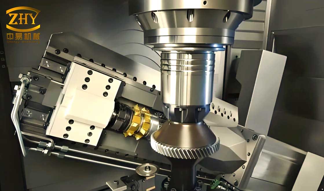
Why Gear Machining Requirements Have Become Extreme
I begin with the demand side because gear machining cannot be separated from the service environment of the gear. A typical electric vehicle reducer uses a single-speed layout with two gear pairs: an input shaft gear connected to the motor, an intermediate shaft gear, and an output gear. The intermediate shaft often carries two gear sections, which increases the complexity of gear machining, clamping, and accuracy control. The motor provides high torque from zero speed, operates with low masking noise, and frequently experiences regenerative braking events that introduce impact and load reversal. These conditions make gear whine, meshing impact, and fatigue failure much more visible than in conventional drivetrains.
To suppress gear whine and improve load carrying capacity, designers apply tooth flank modification such as profile crowning, lead crowning, bias modification, pressure angle modification, and helix angle modification. Such modifications reduce transmission error and mesh impact, but they also make gear machining more difficult because the modified tooth surface must be generated with high geometric fidelity. At the same time, surface integrity parameters such as surface texture, roughness, waviness, and residual stress have become equally important. I see the modern challenge of gear machining as a coupled problem: the process must generate the intended macro geometry and the intended micro and meso surface state simultaneously.
The scales of surface integrity can be organized as follows.
| Scale | Typical parameter | Main physical origin | Effect on gear performance | Primary control variables in gear machining |
|---|---|---|---|---|
| Macro | Surface texture, lay direction | Tool motion trajectory, stroke, additional axes | Lubrication, contact stress, mesh noise, ghost frequency | Stroke speed, axis synchronization, tool path, workpiece mounting angle |
| Meso | Waviness | Machine vibration, tool wear, installation error, kinematic error | Transmission error, contact pattern, sound quality | Spindle vibration, feed rate, machine stiffness, thermal drift |
| Micro | Roughness | Abrasive grit shape, protrusion, spacing, wear | Friction, stress concentration, lubrication film | Grit size, bond, wheel speed, feed, dressing |
| Subsurface | Residual stress | Mechanical deformation and thermal gradient | Fatigue life, crack initiation, contact fatigue | Grinding force, temperature, cooling, honing speed |
I emphasize that the effect of these parameters is not independent. In dry or starved-lubrication conditions, roughness can dominate noise generation. When an oil film forms, roughness effects are reduced and waviness becomes more important. Residual compressive stress can improve fatigue life, but excessive grinding heat can reduce compressive stress or even create tensile stress. Therefore, gear machining must be understood as a multi-scale surface generation process rather than a single accuracy operation.
Hard Finishing Routes and Process Kinematics
I now turn to the dominant process chain. Gear manufacturing usually follows a sequence of soft roughing, heat treatment, and hard finishing. Heat treatment distortion cannot be predicted with sufficient accuracy for many production cases, so hard finishing remains the critical step that determines final service performance. Although many finishing methods exist, including magnetic polishing and abrasive flow finishing, the automotive industry is still dominated by high-productivity precision grinding and honing processes. For new energy vehicle gears, the two most important routes are worm wheel grinding and internal meshing power honing.
Both processes belong to generating machining. The tool and workpiece maintain a crossed-axis helical gear meshing relation. Material removal occurs through the relative sliding and scratching of abrasive grains on the tooth surface. The fundamental meshing condition is that the relative velocity vector at the contact point must be perpendicular to the common normal:
$$ \mathbf{v}_{rel} \cdot \mathbf{n} = 0 $$
For worm wheel grinding, the contact condition can be expressed in a general implicit form:
$$ f_g(\phi_g,\Sigma_g,\beta_b,r_b,\mu,\theta_g,v_f)=0 $$
For internal meshing power honing, the contact condition can be written as:
$$ f_h(\tau_h,\phi_h,\Sigma_h,p_h,a_h,r_b,i_h)=0 $$
These equations mean that the contact trace and the instantaneous motion must be coordinated at every instant. If the coordination is imperfect, the generated tooth surface will deviate from the target modification. This is one reason why gear machining equipment requires high dynamic stiffness, precise electronic gearbox synchronization, and accurate thermal compensation.
The grinding speed in worm wheel grinding is dominated by the wheel rotation because the wheel speed is much higher than the workpiece speed. A simplified representation is:
$$ v_{gr} = \sqrt{v_{gr,t}^2 + v_{gr,f}^2} $$
$$ v_{gr,t} = 2\pi n_{wheel} r_{wheel} $$
$$ v_{gr,f} = 2\pi n_{work} r_{work} $$
For power honing, the honing speed has a more complex distribution because the relative sliding velocity changes across the tooth flank. Near the pitch line, the profile-direction component can approach zero, while the lead-direction component depends on the distance from the workpiece axis. A simplified form is:
$$ v_{hon} = \sqrt{v_{hon,t}^2 + v_{hon,f}^2} $$
$$ v_{hon,t} = 2\pi n_{hone} r_{hone}\sin\Sigma_h\cos\beta_h $$
$$ v_{hon,f} = 2\pi n_{hone}\left(\rho_h-\rho_{hone}\right) $$
Because of these kinematic differences, worm wheel grinding tends to produce parallel or near-parallel lay patterns, while power honing tends to produce a crossed or herringbone-like pattern. The texture difference directly affects noise and lubrication. The process comparison is summarized in Table 2.
| Feature | Worm wheel grinding | Internal meshing power honing |
|---|---|---|
| Typical cutting speed | Up to about 80–100 m/s | Often about 5–20 m/s |
| Material removal rate | High | Moderate to low |
| Heat generation | High, risk of burn | Low, usually no burn |
| Surface texture | Parallel or adjustable lay | Crossed or herringbone lay |
| Residual stress | Can be compressive but sensitive to heat | Usually stronger compressive stress |
| Error correction ability | Good for profile and lead | Strong correction of prior errors |
| Main limitation | Thermal damage, wheel wear, ghost noise | Machine tool stiffness, tool life, limited size range |
| Typical role in gear machining | Main hard finishing process | Final finishing for low noise and high surface integrity |
Grinding Force and Its Role in Gear Machining
In my view, grinding force is one of the most informative process signatures in gear machining because it connects kinematic parameters, tool topography, material removal, heat generation, and surface integrity. Force models for gear machining have evolved from empirical regression to geometric interference and chip-volume-based models. A general form is:
$$ F_t = K_c \frac{Q_w}{v_s} + F_0 $$
where the tangential force depends on the specific cutting energy, the material removal rate, and the cutting speed. More detailed models divide the contact zone into regions and calculate the undeformed chip thickness from the intersection between the tool and workpiece. For honing, the force model must account for the changing contact path and the variable sliding speed across the tooth flank.
A chip-volume-based force model can be expressed as:
$$ F_t = K_c \sum_{i=1}^{N} b_i h_i^{1-\epsilon} $$
where the sum is over active abrasive grains, and the local chip thickness depends on the local grain protrusion and the relative motion. This kind of model is useful because it can be linked to surface roughness and residual stress.
| Modeling approach | Core idea | Advantages | Limitations |
|---|---|---|---|
| Empirical regression | Fit force to feed, speed, and depth | Simple, fast for shop-floor use | Poor transferability across tools and machines |
| Geometric interference | Compute contact between wheel and gear flanks | Accounts for process kinematics | Sensitive to tool topography assumptions |
| Chip-volume integration | Sum local grain cutting forces | Can predict distributed force | Requires accurate grain distribution |
| Finite element method | Model tool–workpiece compliance and contact | Can include elasticity and dynamics | High computational cost |
| Hybrid physical–data model | Combine mechanism with sensor data | Better adaptation to real gear machining | Needs sufficient training data |
Force measurement in gear machining is difficult because the contact zone is often enclosed and rotating. I have seen three practical strategies. The first is to mount a rotary dynamometer on the workpiece spindle, but this requires careful separation of one-flank contact and sufficient overlap. The second is to use acoustic emission sensors on the spindle to infer wheel loading and material removal. The third is to use strain sensors on the machine slide to estimate the force indirectly. Each method has trade-offs between bandwidth, sensitivity, and integration complexity.
| Measurement method | Location | Measured quantity | Strength | Weakness |
|---|---|---|---|---|
| Rotary dynamometer | Workpiece spindle | Force and torque | Direct and quantitative | Cost, fixture complexity, dynamic interference |
| Acoustic emission | Wheel spindle or table | High-frequency emission | Fast response, wheel condition sensitive | Indirect, sensitive to coolant and noise |
| Strain sensor | Feed axis or support | Deformation or load | Easy to integrate | Calibration drift, cross-talk |
| Spindle power | Drive motor | Power or current | No additional sensor in contact zone | Low bandwidth, many influencing factors |
Grinding Heat and Thermal Damage in Gear Machining
Worm wheel grinding is a high-speed process, and a large fraction of the grinding energy is converted into heat. If the heat is not controlled, the tooth surface can suffer burn, tempering, microcracks, and a reduction in compressive residual stress. The specific grinding energy can be written as:
$$ e_c = \frac{F_t v_s}{Q_w} $$
where the material removal rate is:
$$ Q_w = a_p b v_w $$
The heat flux entering the workpiece is often approximated by a partition ratio:
$$ q_w = \frac{1}{1+\sqrt{(k\rho c)_w/(k\rho c)_s}} q_{total} $$
and the total heat flux is:
$$ q_{total} = \frac{F_t v_s}{A_c} $$
These equations show why increasing removal rate and chip thickness can sometimes reduce specific energy. If the abrasive grains cut rather than rub, the energy per unit volume decreases. This is one reason why controlled grain engagement and proper dressing are important in gear machining.
Thermal modeling in gear machining usually follows a sequence: calculate uncut chip geometry, compute heat flux, solve a moving heat source problem, and compare the predicted temperature with measurements. Measurement can be performed with embedded thermocouples, infrared sensors, or specially designed grinding thermocouples. The challenge is that the contact is intermittent and the temperature field is highly localized.
| Thermal aspect | Model or method | Key output | Practical use |
|---|---|---|---|
| Heat generation | Sliding, plowing, cutting energy decomposition | Heat flux distribution | Parameter selection |
| Heat partition | Wheel–workpiece–chip–fluid partition | Workpiece heat fraction | Burn prediction |
| Temperature field | Moving heat source, finite element method | Surface and subsurface temperature | Cooling design |
| Cooling effect | Fluid supply rate and jet orientation | Convection and film boiling | Nozzle optimization |
| Measurement | Thermocouple, infrared, embedded sensor | Peak temperature | Model validation |
For internal meshing power honing, the cutting speed is much lower, so thermal damage is generally not the dominant problem. Instead, the mechanical action of the honing grains produces a favorable compressive residual stress and a fine surface finish. This is why I regard power honing as a strong candidate for final gear machining of low-noise electric vehicle gears.
Surface Texture, Roughness, and Waviness in Gear Machining
Surface integrity is where gear machining becomes most sensitive to process detail. I separate the discussion into texture, roughness, waviness, and residual stress.
Surface texture is the macro-scale lay pattern. In worm wheel grinding, the lay is often parallel to the lead direction. This can generate a pronounced ghost frequency or mesh whine at high speed. To reduce this risk, several methods have been proposed. One is to modulate the stroke speed with a periodic function so that the texture becomes irregular. Another is to mount the workpiece at a small angle so that the lay direction is inclined. A third is to introduce additional synchronized motion through a flexible electronic gearbox. In power honing, the crossed-axis motion naturally produces a herringbone pattern, which is often beneficial for noise and lubrication.
Roughness is the micro-scale result of abrasive scratching. A simplified model can be written as:
$$ R_a \approx C \left(\frac{v_f}{v_s}\right)^\alpha \left(\frac{a_p}{d_g}\right)^\beta \left(\frac{1}{V_g}\right)^\gamma $$
where the exponents depend on the material, abrasive, and wear state. This model is useful for understanding trends, but accurate prediction requires the actual abrasive topography and kinematic trajectory. In gear machining, the roughness varies along the tooth profile because the sliding speed and contact pressure are not uniform. In power honing, the roughness often increases from the root to the tip and changes with the crossed-axis angle.
Waviness is the meso-scale deviation that lies between form error and roughness. It has become a central concern because it can dominate noise when the oil film is thick enough to separate roughness peaks. A general representation is:
$$ w(x,y) = \sum_{i=1}^{n} A_i \sin(2\pi f_i x + \phi_i)\sin(2\pi g_i y + \psi_i) $$
In gear machining, waviness is created by a combination of tool motion, spindle vibration, installation error, wheel wear, and thermal drift. The frequency content is especially important because a waviness component near a mesh harmonic can excite strong vibration. I believe that quantitative waviness modeling is still less mature than roughness modeling. Many production lines still rely on vibration monitoring and trial-and-error adjustment to reduce ghost noise.
| Surface feature | Dominant cause in gear machining | Typical evaluation | Effect on electric vehicle gears |
|---|---|---|---|
| Texture | Tool path and additional axis motion | Lay direction, pattern density | Ghost frequency, lubrication, contact stress |
| Roughness | Abrasive size, protrusion, feed, speed | Ra, Rz, Rq | Friction, noise in dry or thin-film contact |
| Waviness | Vibration, error motion, wheel wear | Amplitude and frequency in length domain | Transmission error, sound quality, mesh excitation |
| Residual stress | Mechanical deformation and temperature | Depth profile, surface value | Fatigue life, crack resistance, contact fatigue |
Residual Stress Generation in Gear Machining
Residual stress is a key subsurface indicator. I model it conceptually as the sum of a mechanical term and a thermal term:
$$ \sigma_{res} = \sigma_{mech} + \sigma_{therm} $$
In low-speed honing, the mechanical term usually dominates and creates compressive stress. In high-speed grinding, the thermal term can become large, reduce the compressive stress, or even create tensile stress. The depth profile depends on the heat penetration and the plastic deformation zone. A compressive residual stress field can delay crack initiation and improve pitting fatigue life. Therefore, gear machining parameters should be selected not only for geometry and roughness but also for the desired residual stress state.
In worm wheel grinding, the residual stress is influenced by the accumulated heat along the lead direction and by the changing contact at the root and tip. In power honing, the residual stress is influenced by the grain spacing and the local sliding speed. Near the pitch line, the scratch density can be higher, which can increase the compressive stress. These effects show that residual stress is a distributed property, not a single number.
Complex Modification in Gear Machining
Complex modification is one of the strongest drivers of advanced gear machining. A modified tooth surface can be described as a nominal surface plus a normal deviation:
$$ \mathbf{p}(u,v) = \mathbf{r}(u,v) + \delta(u,v)\mathbf{n}(u,v) $$
The deviation function can include profile crowning, lead crowning, twist compensation, and higher-order terms. The generation of such a surface requires the tool and workpiece motion to follow a corresponding envelope. A point-vector envelope method can be used to compute the family of contact points and avoid singularities. In practice, the machine must control multiple axes simultaneously. The additional motion can be introduced into the wheel radial feed, wheel axial feed, workpiece rotation, or tool swivel axis.
For worm wheel grinding, twist is a common problem. It appears when the modification is not generated symmetrically on the two flanks. Two practical compensation strategies are continuous diamond roller deflection and worm wheel lead optimization. The first is suitable when the left and right profile slope errors have opposite signs. The second is suitable when the errors have the same sign. In both cases, the goal is to keep the contact trace aligned with the target modification.
For power honing, complex modification can be achieved by adding polynomial or harmonic motions to the honing wheel swivel, workpiece rotation, or radial feed. A general additional motion can be written as:
$$ \Delta q_i(t) = \sum_{k=1}^{m} a_{ik} t^k + \sum_{j=1}^{n} b_{ij} \sin(\omega_j t + \varphi_j) $$
The coefficients are solved from the desired tooth surface deviation. This approach avoids the need for a custom-modified tool and increases flexibility. However, it also increases the demand on the electronic gearbox and the dynamic response of the machine axes.
| Modification type | Typical target | Generation strategy in gear machining | Main challenge |
|---|---|---|---|
| Profile crowning | Reduce mesh impact | Wheel profile dressing or additional radial motion | Profile accuracy along the flank |
| Lead crowning | Improve contact pattern | Workpiece swivel or wheel axial motion | Twist and contact trace control |
| Bias modification | Control contact path | Multi-axis additional motion | Synchronization and dynamic error |
| Twist compensation | Reduce transmission error | Diamond roller deflection or lead optimization | Left and right flank differences |
| Topological modification | Optimize NVH and stress | Closed-loop multi-axis control | Machine tool bandwidth and calibration |
Machine Error Compensation and Parameter Optimization
In my view, gear machining accuracy is limited by two broad error classes: geometric error and thermal error. Geometric error can be divided into position-independent geometric errors and position-dependent geometric errors. For a linear axis, there are six position-dependent errors and three squareness errors. For a rotary axis, there are six position-dependent errors and additional position-independent errors. A general error model can be written as:
$$ \mathbf{E} = \sum_{i=1}^{n} \mathbf{J}_i \Delta \mathbf{q}_i $$
where the Jacobian maps axis errors to tooth surface errors. If the inverse Jacobian is available, compensation can be applied:
$$ \Delta \mathbf{q}_{comp} = -\mathbf{J}^{-1}\mathbf{E} $$
Thermal error is more difficult because it is time-dependent and nonlinear. A common model form is:
$$ \Delta T = f(P, t, \tau) $$
where the temperature field depends on power, time, and thermal time constants. Advanced methods use deep learning, edge-cloud-fog architectures, and segmented hysteresis models to predict thermal error. After prediction, the compensation can be superimposed on the geometric compensation. For gear machining, this means that the tooth surface error can be controlled in real time if the machine has sufficient computational and communication capability.
| Error type | Source | Typical effect | Compensation approach |
|---|---|---|---|
| Position-independent geometric error | Assembly, squareness, axis offset | Systematic profile and lead error | Calibration and kinematic correction |
| Position-dependent geometric error | Guideway straightness, angular error | Position-varying tooth surface error | Error map and real-time compensation |
| Thermal error | Spindle, motor, coolant, environment | Drift and gradual accuracy loss | Thermal model and online compensation |
| Dynamic error | Vibration, servo lag, cutting force | Waviness and surface defects | Dynamic stiffness, active damping, feedforward |
| Tool error | Wear, dressing error, runout | Profile deviation and roughness change | In-process dressing and wear compensation |
Parameter optimization in gear machining is often multi-objective. I can write a generic optimization problem as:
$$ \min \mathbf{F}(x) = \left[ -E_{ff}, R_a, E_{profile}, w, \sigma_{res}, T_{burn} \right]^T $$
where the decision vector is:
$$ x = \left[ v_s, v_f, a_p, n_w, \Sigma, t_{spark} \right]^T $$
The objectives may include maximizing material removal rate, minimizing roughness, minimizing profile error, minimizing waviness, maximizing compressive residual stress, and avoiding burn. Because the objectives conflict, a Pareto-based method or weighted decision method is usually needed. The table below summarizes common optimization targets and variables.
| Process | Optimization target | Decision variables | Typical outcome |
|---|---|---|---|
| Worm wheel grinding | Profile error, transmission error | Wheel radial feed, axial feed, workpiece speed | Improved geometric accuracy |
| Worm wheel grinding | Efficiency, wheel life, roughness | Wheel speed, radial feed, axial feed | Balanced productivity and surface quality |
| Worm wheel grinding | Roughness and spindle vibration | Wheel speed, axial feed, radial feed | Suppressed chatter marks |
| Power honing | Profile, lead, pitch errors | Honing speed, axial feed, radial feed, spark-out time | Better gear precision |
| Power honing | Roughness | Honing speed, axial feed, radial feed | Lower Ra and better NVH |
| Power honing | Honing force | Workpiece speed, axial feed, radial feed | Stable cutting and reduced tool damage |
Although many optimization studies exist, I observe a gap: waviness is still rarely used as a direct optimization objective. Most industrial systems monitor vibration and adjust parameters by trial and error. A more systematic approach should link waviness frequency and amplitude to machine error motion and then compensate the specific harmonic components. This is a promising direction for gear machining research.
Tool Wear and Dressing in Gear Machining
Tool condition is another pillar of high-efficiency precision gear machining. In worm wheel grinding, wear progresses from the root to the tip of the worm profile. The wear includes attritious wear, grain fracture, and adhesion of chips. A fractal dimension can be used to quantify the worn surface:
$$ D_f = \frac{\log N(\varepsilon)}{\log(1/\varepsilon)} $$
where a change in fractal dimension indicates a change in roughness and cutting ability. The grinding speed is a major factor in wear, and dressing parameters also affect the worn topography. If the dressing amount or dressing speed is outside the proper range, the wheel surface can lose its sharpness and the gear machining quality can deteriorate.
For power honing, the honing wheel wear is different because the cutting speed is low. Vitrified bonded wheels often have higher porosity and larger chip thickness, which can produce higher material removal but also higher wear. Resin bonded wheels tend to produce smaller chip thickness, lower wear, and a stronger plowing effect, which can create compressive residual stress. This trade-off must be considered in tool selection for gear machining.
Dressing is essential to maintain the tool profile and cutting capability. For worm wheels, a form diamond roller or a spherical diamond roller can be used. For honing wheels, diamond dressing gears and variable-speed dressing tools are common. A critical issue is that dressing with a fixed crossed-axis angle can change the gear profile, so variable-axis-angle dressing has been proposed. This requires multi-axis electronic gearbox control and precise synchronization.
| Tool issue | Process | Monitoring or evaluation | Control strategy |
|---|---|---|---|
| Worm wheel wear | Worm wheel grinding | Surface fractal dimension, acoustic emission, force | Dressing interval, speed adjustment, feed compensation |
| Honing wheel wear | Power honing | Force, surface roughness, profile error | Bond selection, grit size, dressing strategy |
| Profile loss | Both | On-machine measurement, touch probe | In-process dressing and compensation |
| Loading and glazing | Worm wheel grinding | Acoustic emission, spindle power | Coolant optimization, dressing depth |
| Dressing tool wear | Both | Dressing force, profile inspection | Tool replacement scheduling |
Equipment for High-Efficiency Precision Gear Machining
The equipment side is as important as the process side. I group gear machining equipment into worm wheel grinding machines, internal power honing machines, and high-performance tools.
Modern worm wheel grinding machines typically offer high wheel speeds, dual spindle configurations, integrated dressing units, and closed-loop measurement. Some machines can perform low-noise shifting, variable-speed grinding, and tooth surface polishing. The closed-loop concept is powerful: after grinding, the gear is measured, the deviation is fed back, and the machine automatically corrects the next workpiece. In my opinion, this closed-loop capability is becoming a standard requirement for high-end gear machining.
Internal power honing machines are less common and more specialized. Two main head designs exist: a ring-shaped honing head and a cup-shaped honing head. The ring-shaped head can use a tailstock for workpiece support and is often used for shafts with multiple gear sections. The cup-shaped head uses a cantilever support and does not require a tailstock, which reduces the honing head size but demands higher machine stiffness and precision. The main limitations of power honing equipment are maximum workpiece diameter, maximum honing wheel speed, maximum crossed-axis angle, and dynamic stiffness. These limitations explain why power honing has not yet replaced grinding in all gear machining applications.
| Equipment aspect | Worm wheel grinding machine | Internal power honing machine |
|---|---|---|
| Typical wheel speed | Up to 100 m/s or more | Up to about 20 m/s |
| Main spindle requirement | High speed, high precision | High torque, high stiffness, large bearing capacity |
| Tool size | Large worm wheel | Large internal honing wheel |
| Workpiece support | Commonly tailstock | Ring type uses tailstock; cup type may not |
| Measurement integration | Often closed-loop with gear tester | Less common but increasing |
| Key challenge | Thermal damage, wheel wear, waviness | Machine stiffness, tool life, size range |
High-performance tools are also advancing. Segmented composite worm wheels allow different abrasive sizes and bonds in different sections, so roughing and finishing can be performed with one tool. Superabrasive wheels, especially cubic boron nitride wheels, offer lower grinding stress, lower grain loss, and better thermal stability. Electroplated diamond honing wheels have also been explored for power honing. However, diamond has a chemical affinity for iron, so cubic boron nitride may be more attractive for steel gear honing. Dressing tools remain a bottleneck. Diamond dressing gears and variable-speed dressing tools are complex to manufacture, and their precision directly determines the honing wheel profile and the final gear machining accuracy.
Emerging Trends in Gear Machining
I now outline the trends that I believe will shape the next generation of gear machining.
Changing Powertrain Architectures
The current research and equipment are largely aimed at single-speed reducers. Future electric drive systems may adopt two-speed transmissions, planetary gear sets, asymmetric gears, or polymer–metal composite gears. Each configuration changes the gear machining requirements. Two-speed systems may require more complex gear geometry and more stringent noise control. Planetary systems introduce multiple meshes and load sharing. Asymmetric gears require different modification on the drive and coast flanks. Polymer or coated gears may require lower-temperature gear machining and different surface treatments. I believe that equipment and process developers should evaluate these possibilities early rather than waiting for mass production demand.
Deeper Understanding of High-Performance Tooth Surface Generation
The current understanding of gear machining is often fragmented. One study may focus on roughness, another on waviness, and another on residual stress. In reality, these parameters interact. A change in grinding speed can reduce roughness but increase thermal damage. A change in feed can reduce waviness but change the residual stress. I therefore advocate a coupled framework:
$$ \text{Service performance} \leftrightarrow \text{Tooth surface generation} \leftrightarrow \text{Process system parameters} $$
This framework should include the following mapping:
$$ \mathbf{Y} = \mathbf{G}(\mathbf{X}, \mathbf{T}, \mathbf{M}, \mathbf{E}) $$
where the output vector includes geometric accuracy, texture, roughness, waviness, and residual stress; the input vector includes process parameters; the tool state is represented by tool topography and wear; the machine state is represented by error motion and dynamics; and the environment includes cooling and temperature. Building such a model is difficult but necessary for truly predictive gear machining.
Condition Monitoring and Dynamic Control
I see condition monitoring as the bridge between mechanism research and industrial application. A modern gear machining system should measure force, vibration, acoustic emission, displacement, and temperature. These signals can be fused to estimate tool wear, contact state, thermal drift, and surface generation quality. A data–physics hybrid model can be written as:
$$ \hat{y} = \alpha f_{phys}(x) + (1-\alpha) f_{data}(x) $$
where the physical model provides interpretability and the data model captures unmodeled effects. With such a model, the controller can adjust feed, speed, or compensation in real time. It can also predict when the wheel needs dressing or when a workpiece is at risk of being out of tolerance. This is the basis of predictive maintenance in gear machining.
| Monitoring target | Sensor | Signal feature | Control action |
|---|---|---|---|
| Grinding force | Dynamometer, strain, spindle current | Amplitude, frequency, mean | Feed override, depth control |
| Vibration | Accelerometer, displacement sensor | RMS, harmonic amplitude | Speed modulation, damping |
| Acoustic emission | AE sensor | Energy, burst count | Dressing decision, burn warning |
| Thermal state | Temperature sensor, thermal model | Drift and gradient | Thermal compensation |
| Surface quality | On-machine probe, optical sensor | Roughness and waviness | Parameter update, rework decision |
Green and Intelligent Equipment
Green gear machining is another trend. High-speed dry grinding, minimum quantity lubrication, and reduced coolant use can lower energy consumption and environmental impact. However, dry grinding increases thermal load, so it requires advanced cooling, optimized wheel topography, and robust thermal compensation. Intelligent equipment should integrate these functions without sacrificing productivity. I expect future gear machining centers to include embedded process models, self-diagnosis, automatic tool dressing, and seamless connection to factory-level data systems.
Multi-energy field-assisted gear machining is also emerging. Laser assistance, ultrasonic vibration, and magnetic fields can change material removal and surface formation. If these fields are properly coupled with mechanical cutting, they may reduce force, improve surface integrity, and extend tool life. For gear machining, the key research question is how the special energy field interacts with the mechanical field at the contact zone.
Superabrasive Tools and In-Process Dressing
Finally, tools will continue to evolve. Cubic boron nitride and diamond abrasives offer high hardness and wear resistance. The challenge is to manufacture them with the required profile and to dress them efficiently. In-process dressing with high-precision diamond rolls will remain a core technology. For power honing, the development of reliable dressing tools is especially urgent. The precision of the dressing tool determines the honing wheel profile, which in turn determines the final gear machining accuracy. I believe that tool and dressing technology will be a major differentiator among gear machining equipment suppliers.
Concluding Perspective
In this article, I have reviewed the main technical elements of high-efficiency precision gear machining for new energy vehicle gears. The central conclusion is that gear machining is no longer a single operation. It is a multi-scale, multi-physics, and multi-objective manufacturing process. The service performance of an electric vehicle gear depends on geometric accuracy, surface texture, roughness, waviness, and residual stress. These properties are generated by the interaction of process kinematics, abrasive topography, machine errors, thermal effects, and dynamic vibration. Worm wheel grinding and internal meshing power honing are the two most important production routes. Worm wheel grinding offers high productivity but faces thermal damage and waviness challenges. Power honing offers excellent surface integrity and error correction but is limited by machine tool capability and tool life.
The most important research direction, in my view, is to establish a quantitative and predictive link among service performance, tooth surface generation, and process system parameters. This requires better models of force, heat, surface topography, and residual stress, as well as better sensors and control algorithms. It also requires equipment that can compensate geometric and thermal errors in real time, dress tools accurately, and monitor its own condition. If these capabilities are developed, gear machining can move from experience-based adjustment to model-based and data-driven precision manufacturing.
For the electric vehicle industry, the payoff is substantial: lower gear whine, higher fatigue life, better efficiency, and greater power density. For the machine tool industry, the opportunity is equally large: new equipment, new tools, and new process intelligence. I therefore conclude that high-efficiency precision gear machining will remain a vital and rapidly evolving field, and that the integration of mechanism, sensing, control, and equipment will define its next stage.