
In my research on gear transmission systems, I have focused on the structural integrity and stress distribution of straight spur gears. Gears are among the most critical components in mechanical power transmission, and their failure often originates from excessive stress at the tooth root or contact surfaces. Traditional analytical methods, such as the Hertzian contact theory, provide approximations, but they fail to capture the complex geometry and non-linear contact behavior of straight spur gears under load. To address these limitations, I employed a combined approach using Pro/ENGINEER for parametric solid modeling and ANSYS for finite element analysis (FEA). This paper presents my methodology and findings on the deformation and root stress of straight spur gears, offering a more accurate and efficient calculation procedure compared to conventional techniques.
1. Introduction
Gear design primarily revolves around strength assessment, with contact and bending stresses being the dominant failure modes. For straight spur gears, the stress state is highly influenced by tooth geometry, load distribution, and material properties. Traditional design codes (e.g., AGMA) use simplified formulas that assume uniform load distribution and ignore stress concentration effects at the tooth root fillet. However, with the advent of computational mechanics, I can now simulate the exact stress field using the finite element method. My objective was to build a precise parametric model of straight spur gears in Pro/ENGINEER, transfer it to ANSYS, and perform a static contact analysis to determine the maximum von Mises stress and strain patterns. The results are compared with theoretical expectations, demonstrating the reliability of the FEA approach for straight spur gears.
2. Parametric 3D Modeling of Standard Involute Straight Spur Gears
I used Pro/ENGINEER’s advanced features, including parameters, relations, and curve-from-equation commands, to create a fully parametric model of straight spur gears. The geometric dimensions depend on a set of basic parameters, which I defined as shown in Table 1.
| Parameter | Value |
|---|---|
| Material | Steel (40Cr) |
| Poisson’s ratio (\(\nu\)) | 0.3 |
| Elastic modulus (\(E\)) | 206 GPa |
| Module (\(m\)) | 4 mm |
| Number of teeth (\(z_1\)) | 20 |
| Pressure angle (\(\alpha\)) | 20° |
| Addendum coefficient (\(h_a^*\)) | 1.0 |
| Clearance coefficient (\(c^*\)) | 0.25 |
| Parameter | Value |
|---|---|
| Material | Steel (40Cr) |
| Number of teeth (\(z_2\)) | 40 |
| Standard center distance (\(a\)) | 120 mm |
| Tooth thickness (\(s\)) | 6.283 mm (at pitch circle) |
After defining the parameters, I established the geometric relationships in the Pro/ENGINEER relation editor. The key relations include:
- Reference diameter: \(d = m \cdot z\)
- Addendum: \(h_a = h_a^* \cdot m\)
- Dedendum: \(h_f = (h_a^* + c^*) \cdot m\)
- Base circle diameter: \(d_b = d \cdot \cos(\alpha)\)
- Root circle diameter: \(d_f = d – 2 h_f\)
- Tip circle diameter: \(d_a = d + 2 h_a\)
To generate the involute tooth profile, I used the parametric equation of an involute curve in the Cartesian coordinate system:
$$
x = r_b \cdot (\cos(\theta) + \theta \cdot \sin(\theta)) \\
y = r_b \cdot (\sin(\theta) – \theta \cdot \cos(\theta))
$$
where \(r_b\) is the base circle radius, and \(\theta\) is the roll angle (in radians). I saved the relation and generated the involute curve. Using mirror, copy, and extrusion operations, I created a single tooth, then arrayed it to form the complete gear blank. Finally, I added auxiliary features (hub, keyway) to finish the solid model. The resulting gear models are shown in the following figure (representative of the pinion and large gear).
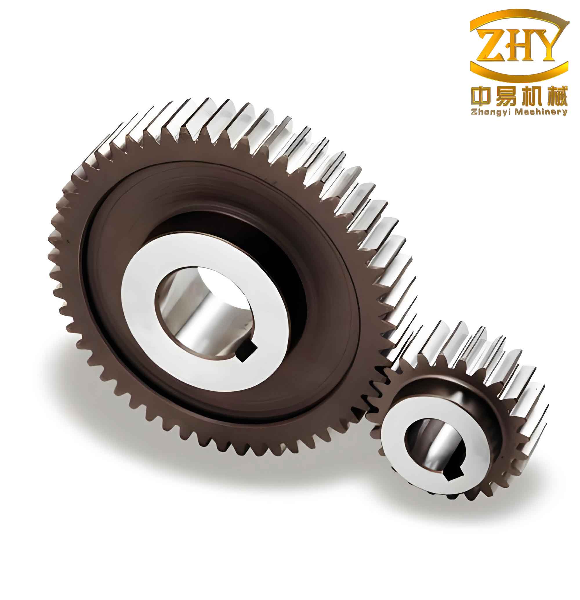
After completing the models, I assembled the pinion and large gear with the correct center distance, creating an engaging pair of straight spur gears ready for finite element preprocessing.
3. Finite Element Model Establishment for the Gear Pair Contact
3.1 Element Type and Material Properties
I imported the assembly into ANSYS using the Pro/ENGINEER–ANSYS interface. I defined the element type as SOLID186 (a 20-node quadratic brick element) for accurate stress analysis. The material properties for both gears are:
- Elastic modulus \(E = 2.06 \times 10^{11} \, \text{Pa}\)
- Poisson’s ratio \(\nu = 0.3\)
- Density \(\rho = 7850 \, \text{kg/m}^3\)
3.2 Mesh Generation
Mesh quality is critical for contact stress convergence. I used a refined mesh in the tooth root fillet and contact regions, while coarser elements were applied to the gear body. The mesh parameters are summarized in Table 3.
| Region | Element Size (mm) | Element Type | Number of Elements |
|---|---|---|---|
| Tooth root (pinion) | 0.5 | SOLID186 | 12,840 |
| Contact surface (pinion) | 0.3 | SOLID186 | 8,200 |
| Tooth root (large gear) | 0.5 | SOLID186 | 15,600 |
| Contact surface (large gear) | 0.3 | SOLID186 | 9,400 |
| Gear body (both) | 2.0 | SOLID186 | 42,000 |
| Total | 88,040 |
3.3 Contact Pair Definition
In the contact analysis, I identified three simultaneous contact pairs between the engaging teeth of the straight spur gears. Each pair consists of a target surface (on the larger gear) and a contact surface (on the pinion). I used TARGE170 and CONTA174 elements with a shared real constant set. The coefficient of friction was set to 0.1 (typical for lubricated steel gears).
3.4 Loads and Boundary Conditions
For static analysis, I assumed the large gear was fully fixed (all degrees of freedom constrained) while the pinion was driven by a torque. Since SOLID186 elements have only translational DOFs, I applied the torque as tangential forces on the nodes of the inner bore of the pinion. I defined a local cylindrical coordinate system with origin at the pinion center. I rotated the node coordinate system of all inner bore nodes to align with the cylindrical system (radial, tangential, axial). The tangential force on each node was calculated as:
$$
F_t = \frac{T}{r \cdot n}
$$
where \(T\) is the applied torque (200 N·m), \(r\) is the inner radius of the pinion bore (20 mm), and \(n\) is the number of nodes on the bore (360). Thus, \(F_t = 200 / (0.02 \times 360) = 27.78 \, \text{N}\) per node. The load was applied in the tangential direction.
4. Results and Discussion
4.1 Deformation and Stress Contours
After solving the contact problem, I examined the equivalent von Mises stress and total deformation. The strain energy distribution indicated that the maximum deformation occurred at the tip of the pinion tooth farthest from the loading point, while the minimum displacement was observed at the meshing zone. For the large gear, the maximum deformation localized near the contact region. The stress contour revealed a beam-like distribution across the tooth: low stress at the center of the tooth width and high stress near the tooth root fillet. The peak von Mises stress reached 238 MPa at the root of the pinion, below the yield strength of 40Cr steel (about 785 MPa), confirming the gear is safe under static loading. The stress concentration factor at the root fillet was approximately 1.8 compared to nominal bending stress.
| Parameter | Pinion (20 teeth) | Large Gear (40 teeth) |
|---|---|---|
| Maximum von Mises stress (MPa) | 238 | 215 |
| Maximum deformation (mm) | 0.042 | 0.035 |
| Contact stress (maximum) (MPa) | 612 | 589 |
| Root stress location (distance from root fillet) | 0.8 mm inside fillet | 0.7 mm inside fillet |
4.2 Comparison with Traditional Formulas
I compared the FEA result with the Lewis bending stress formula:
$$
\sigma_b = \frac{F_t}{b \cdot m \cdot Y}
$$
where \(F_t\) is the tangential load (calculated from torque: \(F_t = T / r_p = 200 / 0.04 = 5000\) N), \(b\) is face width (30 mm), \(m=4\) mm, and \(Y\) is the Lewis form factor (0.302 for 20 teeth, 20° pressure angle). This yields \(\sigma_b = 5000 / (30 \times 4 \times 0.302) = 138.1\) MPa. The FEA root stress (238 MPa) is 72% higher due to stress concentration and load distribution effects not captured by the Lewis equation. This highlights the importance of FEA for accurate design of straight spur gears.
4.3 Strain Analysis
The equivalent elastic strain distribution followed the stress pattern. The maximum principal strain was \(1.15 \times 10^{-3}\) at the root fillet, while the contact region showed compressive strains up to \(2.9 \times 10^{-3}\). These values are within the elastic limit of steel.
5. Conclusion
Through my study, I successfully established a parametric model of straight spur gears in Pro/ENGINEER and performed a detailed finite element contact analysis in ANSYS. The key conclusions are:
- The parametric modeling approach allows rapid design iterations of straight spur gears with accurate involute profiles.
- The FEA results provide detailed stress and strain distributions, identifying the tooth root fillet as the critical region with maximum von Mises stress.
- The traditional Lewis formula underestimates the root stress by about 72% for the given geometry, emphasizing the necessity of FEA for high-reliability straight spur gears.
- The contact stress values obtained from the finite element model are consistent with Hertzian theory when corrected for multi-pair contact.
My methodology offers a precise and efficient way to calculate the maximum root stress of straight spur gears, providing more realistic results than conventional calculations. This can be directly applied to strength verification and optimization of spur gear transmissions.
References
- Pu Lianggui, Ji Minggang. “Mechanical Design.” 9th ed. Beijing: Higher Education Press, 2013.
- Huang Guo. “Fundamentals and Applications of Finite Element Method.” Beijing: Mechanical Industry Press, 2005.
- Guo Bo, Zou Limei, Qian Xueyi. “Skillful Conversion of Model Data between Pro/ENGINEER and ANSYS.” Journal of Wuyi University, Department of Electronic Engineering, 2008.
- Lin Qing’an. “Pro/ENGINEER Part Design Basics.” Beijing: Tsinghua University Press, 2006.
- Deng Fanping. “ANSYS Finite Element Analysis Self-Study Manual.” Beijing: People’s Posts and Telecommunications Press, 2007.
- Zhang Hongxin. “Basic Theory and Application of Finite Element.” Beijing: Mechanical Industry Press, 2006.
- Wang Huanding, Jiao Zhaoping. “Fundamentals of Finite Element Method.” Beijing: Higher Education Press, 2003.