
In our research on oilfield pumping units, we encountered a critical issue: many pumping unit reducers were operating under frequent overload conditions, especially during the downstroke when the balance was excessive. The original reducers, such as the CYJ 10‑3‑53HB model, often experienced torque surges beyond their rated capacity. To solve this without modifying the entire pumping unit structure, we proposed a novel concept – tooth stagger for double circular arc herringbone gears. By simply shifting one side of the herringbone gear by half a circular pitch relative to the other side, we could increase the minimum number of simultaneously contacting points, thereby significantly enhancing the load capacity. This paper presents the theoretical foundation, meshing characteristic analysis, and practical application of tooth stagger in herringbone gears.
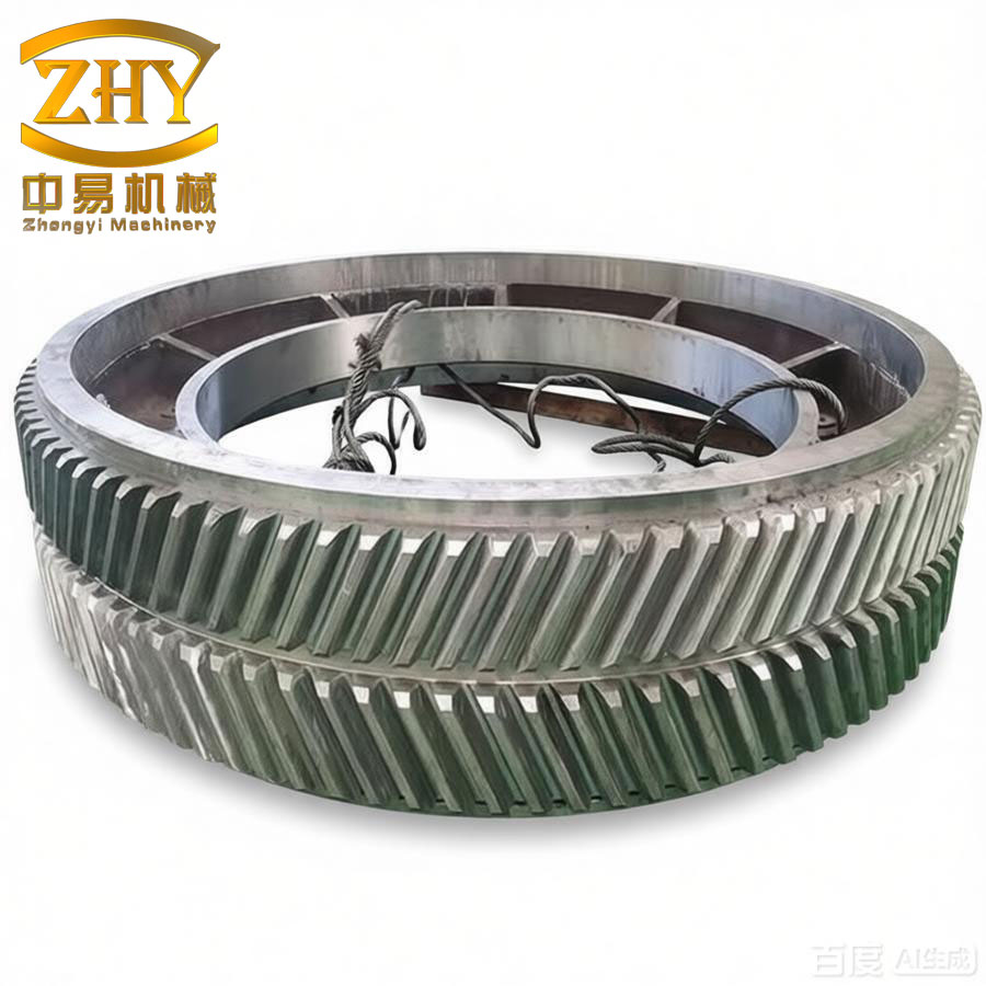
Tooth stagger is defined as follows. In a conventional herringbone gear, the left-hand and right-hand helical teeth are symmetrically arranged with convex tooth surfaces on one side aligning with convex surfaces on the opposite side, and concave surfaces with concave surfaces. In the tooth stagger design, the left-hand teeth (or right-hand teeth) are shifted axially by half of the circular pitch relative to the right-hand teeth (or left-hand teeth). This results in a configuration where convex surfaces on one side face concave surfaces on the opposite side, and vice versa. The schematic arrangement of a conventional herringbone gear and a staggered one is illustrated in the figure below.
Let us denote the axial pitch of the gear as \(P_t\). For a gear with normal module \(m_n\) and helix angle \(\beta\), the axial pitch is:
$$
P_t = \frac{\pi m_n}{\sin\beta}
$$
In a conventional herringbone gear with total face width \(B\) (including a central gap for the hob runout), the number of axial pitches contained in half the face width \(b\) (one side) is an integer part plus a fractional part. The minimum number of simultaneous contact points for a double circular arc herringbone gear is determined by the integer part of the contact ratio \(\mu_0\) and the fractional part \(\Delta\mu\). Our analysis focused on a specific reducer model (CYJ 10‑3‑53HB) with parameters: \(m_n = 8\ \text{mm}\), \(\beta = 28.144^\circ\), \(b = 70\ \text{mm}\) (half face width), and using the GB 12759‑91 double circular arc tooth profile. The axial pitch \(P_t\) was computed as:
$$
P_t = \frac{\pi \times 8}{\sin 28.144^\circ} \approx 53.48\ \text{mm}
$$
The half face width \(b = 70\ \text{mm}\) contains 1 full axial pitch and a remainder of \(16.52\ \text{mm}\). Therefore, the integer part \(\mu_0 = 1\) and the fractional part \(\Delta\mu = 16.52 / 53.48 \approx 0.309\). With the conventional arrangement, the minimum number of contact points on one side is \(\mu_0 = 1\), leading to a total of 2 points across both sides of the herringbone gear (since each side contributes one point).
When tooth stagger is applied, the relative axial shift of one half-pitch means that the convex and concave surfaces on the opposite sides are offset. The effective contact pattern changes such that the minimum number of simultaneous contact points increases. For the same gear geometry, after staggering, the integer part of the contact ratio effectively becomes \(\mu_0′ = \mu_0 + 1 = 2\) on one side, because the staggered configuration allows an additional contact point within the same face width. The fractional part also changes slightly. Detailed meshing analysis of the high-speed stage and low-speed stage of the reducer is presented in Tables 1 and 2.
| Configuration | Left side (half width b) | Right side (half width b) | Total (full width B = 2b) |
|---|---|---|---|
| Conventional herringbone | 1 → 2 points (oscillating) | 1 → 2 points | Min. 4 points |
| Staggered herringbone | 2 → 3 points | 2 → 3 points | Min. 6 points |
| Configuration | Left side (half width b) | Right side (half width b) | Total (full width B = 2b) |
|---|---|---|---|
| Conventional herringbone | 2 → 3 points | 2 → 3 points | Min. 5 points |
| Staggered herringbone | 3 → 4 points | 3 → 4 points | Min. 7 points |
As shown in the tables, the minimum number of simultaneous contact points increased by 2 points (from 4 to 6) in the high-speed stage and by 2 points (from 5 to 7) in the low-speed stage. This increase directly affects the load capacity of the herringbone gears.
The contact strength and bending strength of double circular arc herringbone gears depend on the minimum number of simultaneous contact points. According to the standard GB 12759‑91, the formulas for surface contact stress and tooth root bending stress are proportional to the square root or the inverse of the number of contact points. Specifically, the contact stress \(\sigma_H\) is given by:
$$
\sigma_H = Z_E Z_H Z_\varepsilon Z_\beta Z_v \sqrt{\frac{2 K_A K_v K_{H\beta} T_1}{b d_1^2 \mu_0 \Delta\mu}}
$$
where \(\mu_0\) is the integer part of the contact ratio on one side, and \(\Delta\mu\) is the fractional tail effect. For a herringbone gear with total width \(B\), the effective number of contact lines is \(\mu_0\) per side, so the total number of contact points is \(2\mu_0\) (plus the fractional contribution). The contact safety factor is:
$$
S_H = \frac{\sigma_{H\lim} Z_N Z_L Z_v}{\sigma_H}
$$
Similarly, the bending stress \(\sigma_F\) is:
$$
\sigma_F = Y_{Fa} Y_{Sa} Y_\varepsilon Y_\beta \frac{2 K_A K_v K_{F\beta} T_1}{b d_1 m_n \mu_0 \Delta\mu}
$$
and the bending safety factor:
$$
S_F = \frac{\sigma_{F\lim} Y_N Y_X}{\sigma_F}
$$
In both formulas, the denominator contains \(\mu_0\) (the integer part of the contact ratio). When tooth stagger increases \(\mu_0\) by 1 on each side, the effective number of contact points effectively rises by 2. Therefore, the stresses decrease proportionally, and the safety factors increase. For the CYJ 10‑3‑53HB reducer, the calculated safety factors for both the high-speed and low-speed stages are summarized in Table 3.
| Stage | Strength type | Conventional herringbone | Staggered herringbone | Capacity increase (%) |
|---|---|---|---|---|
| High-speed | Contact | 1.52 | 1.86 | 22.4 |
| Bending | 1.68 | 2.05 | 22.0 | |
| Low-speed | Contact | 1.35 | 1.60 | 18.5 |
| Bending | 1.48 | 1.75 | 18.2 |
From Table 3, the safety factors for both contact and bending strength improved by approximately 18–22% after applying tooth stagger. This means that the load capacity of the reducer increased by the same margin. In other words, the enhanced herringbone gears could withstand higher torque without requiring any changes to the housing, shaft, or bearing arrangements.
We further extended the principle by slightly increasing the face width of the low-speed stage (from 70 mm to 90 mm) while maintaining the same tooth stagger. This allowed the minimum number of simultaneous contact points in the low-speed stage to increase by an additional point, achieving a total capacity improvement of over 30% for the entire reducer. Consequently, the original CYJ 10‑3‑53HB reducer could be upgraded to match the performance of a larger CYJ 10‑3‑73HB reducer, meeting the needs of heavy crude oil extraction without modifying the pumping unit structure.
The field application of staggered herringbone gears in pumping unit reducers has been highly successful. Several units that previously suffered from overload failures were retrofitted with staggered double circular arc herringbone gears. After more than a year of continuous operation, no gear failure or excessive wear was observed. The oil production efficiency improved, and the maintenance costs were significantly reduced.
In conclusion, the tooth stagger technique for double circular arc herringbone gears is a simple, cost‑effective, and highly beneficial method to enhance the load capacity of reducers used in petroleum, metallurgy, and other heavy industries. By properly selecting the face width and applying a half‑pitch axial shift, the minimum number of simultaneous contact points can be increased by 2 or more, leading to a 15–30% increase in load capacity. Given the widespread use of herringbone gears in pumping unit reducers (over 10,000 units produced annually in China alone), the adoption of tooth stagger can bring substantial economic and technical benefits. We strongly recommend this technology for further promotion in oil field equipment.