
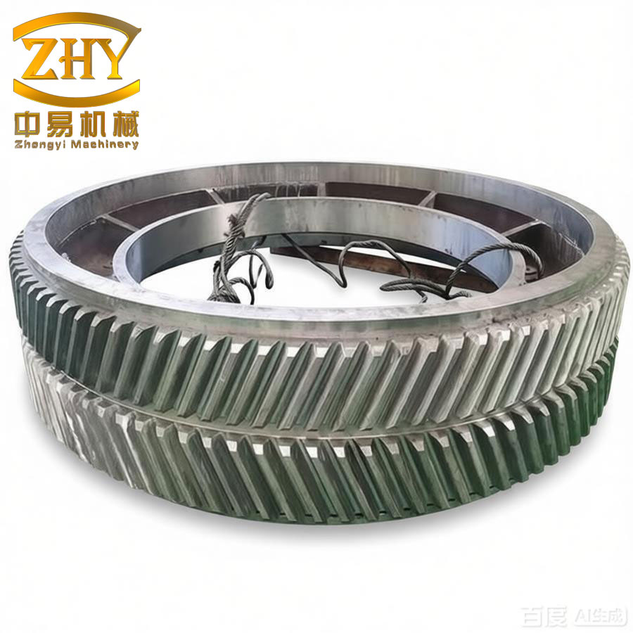
During the installation of a 630 t mechanical press at a client site, I encountered a critical failure in the main drive herringbone gears. The gear wheel hub was made of 35 steel, and the spoke plate was Q235-A steel. A large area of cracks appeared at the root of the 15 mm fillet weld between the hub and the spoke plate, extending over half of the hub circumference. A 0.04 mm feeler gauge could be inserted to a depth of 6–7 mm locally, causing partial separation of the spoke plate from the hub. The structural configuration of these herringbone gears is shown in the figure below.
The gear had been originally welded using CO₂ gas shielded welding with a preheat of 200 °C, a process that had proven reliable for years. However, production records revealed that the far‑infrared heating furnace malfunctioned, and the gear was preheated using a wood‑charcoal flame. Inadequate and uneven preheating led to high internal stresses and the formation of hardened microstructure near the weld toe. Although no cracks were detected immediately after welding, post‑weld heat treatment, or machining, the combined effect of service loads during machine trial and the residual stress triggered delayed cracking. The crack originated at the interface between the base metal (35 steel) and the weld metal, propagated into the heat‑affected zone along the stress concentration region, and exhibited a bright metallic surface typical of a toe crack in herringbone gears welded structures.
Material Analysis and Crack Mechanism
To confirm the material properties, I took samples from the hub. Chemical composition analysis yielded a carbon content of 0.40 %, which is at the upper limit for 35 steel, with other elements within specification. The carbon equivalent (CE) can be calculated using the formula for medium carbon steel:
$$
CE = C + \frac{Mn}{6} + \frac{Cr + Mo + V}{5} + \frac{Ni + Cu}{15}
$$
For 35 steel (typical composition: C 0.32–0.40 %, Mn 0.50–0.80 %, Si 0.17–0.37 %, Cr ≤ 0.25 %, Ni ≤ 0.25 %), the CE is approximately 0.45–0.55 %. This level indicates a certain tendency for hardening under rapid cooling, especially when preheat is insufficient. The combination of high carbon content and fast cooling from the flame preheating (which was both uneven and low temperature) promoted the formation of martensite or bainite in the HAZ, increasing the susceptibility to hydrogen‑induced delayed cracking. The thermal stress due to temperature gradients can be expressed as:
$$
\sigma_{th} = E \alpha \Delta T
$$
where \(E\) is the elastic modulus (~210 GPa for steel), \(\alpha\) is the coefficient of thermal expansion (~12 ×10⁻⁶ / °C), and \(\Delta T\) is the temperature difference between the weld zone and the surrounding base metal. With a low and uneven preheat, \(\Delta T\) increased, leading to higher thermal stresses that combined with the transformation stresses to trigger cracking. This type of failure is commonly observed in large herringbone gears when welding conditions are not strictly controlled.
Repair Strategy: Cold Welding with Transition Layer
Given the urgency of commissioning and the inability to preheat locally on‑site (the press crossbeam was side‑positioned, making heating difficult), I decided to adopt a cold welding repair method. To minimize distortion and avoid further cracking, the following key principles were applied:
- Use of austenitic stainless steel electrodes (A302) for the first layer to dilute the carbon content and reduce hardenability.
- Low‑hydrogen electrodes (J507) for the filling passes to minimize hydrogen content and enhance crack resistance.
- Small weld beads with controlled interpass temperature to keep heat input low and reduce shrinkage stresses.
- Peening each weld bead immediately after deposition to relieve tensile stresses.
This approach is especially effective for repairing herringbone gears where dimensional accuracy must be maintained and preheating is not feasible.
Welding Procedure in Detail
Pre‑weld Preparation
The gear was rotated so that the crack area was accessible in the horizontal‑vertical (2G) position. Dial indicators were placed on the side of the gear ring to monitor deformation during welding. Two 5 mm diameter stop holes were drilled at the crack tips to prevent further propagation. Using a J422 electrode (φ5 mm) with arc gouging, I removed the cracked material and created a U‑ or V‑shaped groove. The groove was ground to a bright metallic finish using an electric grinder. All oil, dust, and residues were cleaned off. The J507 electrodes (φ3.2 mm and φ4 mm) were baked at 350 °C for 2 h; the A302 electrodes (φ3.2 mm) were baked at 350 °C for 1.5 h to ensure low moisture content.
Welding Execution
The welding parameters used for the repair of the herringbone gears are summarized in the following table:
| Layer | Electrode type & diameter (mm) | Current (A) | Polarity | Interpass temperature | Technique |
|---|---|---|---|---|---|
| Transition layer | A302 φ3.2 | 110 | DC reverse | ≤ 50 °C (cool to hand warm) | Short arc, weave, fill crater |
| Filling layers | J507 φ3.2 | 120 | DC reverse | ≤ 50 °C | Short arc, peening after each pass |
| Cover layer | J507 φ4.0 | 160 | DC reverse | ≤ 50 °C | Peening, insulation with asbestos blanket after completion |
The first layer was deposited using A302 (austenitic) at low current (110 A) to create a ductile, carbon‑diluting barrier on the groove surface. This reduces the effective carbon content in the fusion zone, decreasing the hardenability. The dilution effect can be estimated by:
$$
C_{diluted} = \frac{A_b C_b + A_w C_w}{A_b + A_w}
$$
where \(A_b\) and \(A_w\) are the cross‑sectional areas of base metal and weld metal melted, and \(C_b\), \(C_w\) their carbon contents. With a thin first layer, the carbon content in the transition zone drops to well below 0.15 %, mitigating quench cracking.
After each pass, I peened the weld bead using a blunt chipping hammer to induce compressive residual stresses. The peening force should be sufficient to plastically deform the weld surface, typically producing a compressive stress of about 200–300 MPa at the surface. The next pass was allowed only when the previous bead had cooled to below 50 °C (hand‑touch test). This strict interpass temperature control minimized heat accumulation and distortion. For the herringbone gears, which are sensitive to thermal distortion due to their complex tooth geometry, this was critical.
The subsequent filling and cover passes were made with J507 (low‑hydrogen) electrodes. Low hydrogen electrodes reduce the risk of hydrogen‑induced cold cracking. The diffusible hydrogen content in J507 is typically below 5 mL/100 g, which is significantly lower than that of common cellulose or rutile electrodes. The crack susceptibility index for hydrogen cracking can be expressed by the formula:
$$
P_{cm} = C + \frac{Si}{30} + \frac{Mn}{20} + \frac{Cu}{20} + \frac{Ni}{60} + \frac{Cr}{20} + \frac{Mo}{15} + \frac{V}{10} + 5B
$$
For 35 steel, \(P_{cm}\) is around 0.25–0.30, which is borderline. With the A302 transition layer, the effective \(P_{cm}\) in the HAZ is reduced, making cold welding feasible.
Post‑weld Treatment
After the final cover pass, the weld area was immediately covered with an asbestos blanket to slow the cooling rate. This provided a mild post‑weld heat treatment effect, allowing hydrogen to diffuse out and reducing residual stresses. The cooling rate after welding is crucial; for herringbone gears, a cooling rate of less than 5 °C/min helps avoid re‑hardening. The temperature history was monitored with a contact thermometer. No additional oven heating was applied because of on‑site constraints, but the insulation blanket effectively maintained a slow cool.
Distortion Measurement and Quality Control
During welding, I continuously monitored the dial indicator placed on the gear ring. The maximum cumulative distortion recorded was 7 mm (radial shrinkage). This was acceptable for the gear’s service, as the tooth flank tolerances allowed up to 10 mm deviation after assembly. The herringbone gears operate with a certain clearance, and the small distortion did not affect meshing. After welding, the weld was visually inspected and subjected to magnetic particle testing (MT) to confirm absence of surface cracks. No indications were found.
The final hardness of the weld and HAZ was measured using a portable Rockwell hardness tester. The results are summarized below:
| Location | Reading 1 | Reading 2 | Reading 3 | Average |
|---|---|---|---|---|
| Weld metal (cover) | 28 | 29 | 28 | 28.3 |
| HAZ (35 steel side) | 32 | 33 | 32 | 32.3 |
| Base metal (35 steel, far from weld) | 22 | 23 | 22 | 22.3 |
The HAZ hardness of 32 HRC is acceptable for a medium carbon steel, well below the typical threshold of 350 HB (≈38 HRC) where cracking risk becomes high. The low hydrogen and controlled cooling contributed to this favorable hardness profile. The herringbone gears have been in operation for over one year without any recurrence of cracking, confirming the effectiveness of the cold welding method.
Comparison with Conventional Preheating Method
For identical herringbone gears repaired in our workshop, we normally use preheating at 200 °C with CO₂ gas welding. The following table compares the two approaches:
| Parameter | Conventional preheat method | Cold welding (this case) |
|---|---|---|
| Preheat temperature | 200 °C (uniform) | None (ambient) |
| Electrode | H08Mn2SiA + HJ431 | A302 + J507 |
| Heat input | Moderate | Low |
| Distortion | ~5 mm (controlled) | 7 mm (acceptable) |
| On‑site feasibility | Difficult (requires furnace) | Easy |
| Risk of heat‑affected zone cracking | Low if preheat is correct | Low with transition layer |
| Operator skill required | Standard | High (peening, interpass control) |
The cold welding method is particularly suitable for field repairs of herringbone gears when heating equipment is unavailable or when the gear cannot be removed. However, it demands careful execution of peening, interpass temperature, and electrode selection.
Metallurgical Considerations for Herringbone Gears
The large size of herringbone gears (often exceeding 1 m in diameter) means that the weld volume is significant, and the restraint is high. The solidification shrinkage of the weld can be expressed as:
$$
\Delta V = \beta V \Delta T
$$
where \(\beta\) is the volumetric thermal expansion coefficient (~35 ×10⁻⁶ / °C for steel), \(V\) is the weld volume, and \(\Delta T\) is the temperature drop from solidus to ambient. For a 15 mm fillet weld of 1 m length, the shrinkage strain in the transverse direction can reach ~1 mm, which must be accommodated by elastic‑plastic deformation. Peening introduces compressive stress to counteract this tensile shrinkage. In the case of herringbone gears, the tooth geometry creates additional stress concentrators; therefore, any repair must ensure a smooth transition between the weld and base metal to avoid notch effects.
I also considered the effect of the A302 transition layer on the formation of intermetallic phases. Austenitic stainless steel (304 type) and carbon steel can form a carburized zone if carbon diffuses from the base metal into the weld. However, with low heat input and a thin first layer, the carbon migration is limited. The diffusion distance can be approximated by:
$$
x = \sqrt{2 D t}
$$
where \(D\) is the diffusion coefficient of carbon in austenite (~10⁻⁶ cm²/s at 1000 °C) and \(t\) is the time at high temperature. For a 50 s cooling time above 800 °C, \(x \approx 0.1\) mm, negligible. Thus, the risk of forming a continuous carbide layer at the interface is minimal, which is essential for the long‑term integrity of herringbone gears.
Conclusion
The successful repair of the cracked herringbone gears demonstrates that cold welding, using a combination of austenitic and low‑hydrogen electrodes, can effectively restore structural integrity without preheating. The key factors are:
- Thorough removal of cracked material and proper groove preparation.
- Low current, short arc, and continuous peening to control residual stresses.
- Strict interpass temperature monitoring to avoid heat buildup.
- Use of a carbon‑diluting transition layer to reduce hardenability.
- Slow cooling under insulation to promote hydrogen diffusion.
This method is now part of our standard practice for on‑site repairs of large herringbone gears where conventional preheating is not feasible. The press has been operating reliably for over a year, and no signs of cracking have been observed at the repaired weld area. For future repairs of similar herringbone gears, I recommend maintaining a detailed welding record, including actual interpass temperatures, peening force (estimated), and distortion measurements, to continuously refine the process parameters.