
We present a comprehensive investigation into the meshing characteristics of helical gear pairs, focusing on an improved potential energy method for calculating time-varying meshing stiffness. Our primary objective is to enhance both computational efficiency and accuracy in the dynamic analysis of gear transmission systems, particularly within the context of printing machinery. By precisely modeling the time-varying meshing stiffness of the helical gear, we aim to gain a deeper understanding of the dynamic behavior of the gear system, thereby providing a theoretical foundation for optimizing gear design and improving overall system performance. This study is motivated by the stringent requirements for stability and precision in modern printing presses, where the dynamic characteristics of the helical gear transmission directly influence print quality.
The helical gear, due to its inherent helical angle, offers smoother and quieter operation compared to spur gears, making it ideal for high-precision applications. However, this same geometry complicates the calculation of meshing stiffness, a key parameter governing gear system dynamics. We propose a refined analytical method based on the potential energy method, integrating the Smith slicing theory and considerations of tooth root geometry and profile modification. This approach is validated against finite element analysis (FEA) and the ISO 6336-1 standard, demonstrating its accuracy and efficiency. Furthermore, we develop a nine-degree-of-freedom coupled dynamic model of a printing press helical gear transmission system to analyze dynamic meshing forces, radial vibrations, and axial vibrations. Our results provide valuable insights into the dynamic behavior of helical gear pairs under realistic operating conditions.
1. Introduction and Background
The “14th Five-Year Plan” for the printing industry emphasizes a shift towards “green, digital, intelligent, and integrated” development to strengthen China’s position as a printing powerhouse. As the core production equipment in printing, the performance of printing presses directly dictates the industry’s production level. The gear transmission system in a printing press is complex, high-precision, and its dynamic characteristics critically affect overall machine stability and print quality. During meshing, the helical gear system is subject to various excitations, including time-varying meshing stiffness, backlash, and friction. Among these, meshing stiffness is an inherent property and a primary internal excitation source. Accurately obtaining the time-varying meshing stiffness of a helical gear is paramount for gear system dynamics research.
Currently, mainstream methods for calculating meshing stiffness are broadly classified into analytical and finite element methods. The potential energy method is a common analytical approach, which simplifies a gear tooth as a cantilever beam on the base circle. However, this method has inherent errors due to its neglect of the tooth root transition curve. Several researchers have improved upon this. For instance, Liu et al. modified the theoretical time-varying meshing stiffness calculation for worm-helical gear pairs using the potential energy method. Mo et al. analyzed the influence of friction on time-varying meshing stiffness. Tian et al. validated the meshing performance advantages of modified gears. Dong et al. studied the trend of time-varying meshing stiffness under different loading conditions for single and double tooth pairs. Traditional methods often fail to accurately account for the tooth root transition curve in helical gears. To address this, Liu et al. proposed a correction algorithm considering this curve and analyzed the impact of different pressure angles on meshing stiffness, validating their theoretical findings experimentally. Xia et al. verified a time-varying stiffness model using the Ishikawa formula and energy method. Other researchers have constructed meshing stiffness models that incorporate failure and lubrication factors, quantifying the impact of defects on stiffness, thus supporting fault diagnosis and gear performance optimization.
Finite element analysis (FEA) discretizes the gear into finite elements, simulating stress, strain, and displacement distribution during meshing to calculate stiffness. Researchers like Wu Luji and Ma Chunhui have validated the effectiveness of improved helical gear stiffness models using FEA. Helical gears are prone to stiffness reduction due to spalling and pitting. Meng et al. developed an irregular pitting model to assess its influence on time-varying meshing stiffness. Zhou et al. and Liu et al. established stiffness models considering friction and wear. Liu et al. further analyzed the effect of friction force on stiffness. Flek et al. calculated meshing stiffness through profile modification design and validated its accuracy in ABAQUS.
In summary, while FEA can accurately simulate complex gear loading and deformation, including nonlinear factors like wear, it suffers from complex modeling, high computational cost, and is not easily accessible. FEA is often used as a benchmark to validate analytical methods. Studies show that the potential energy method can maintain accuracy while significantly reducing computational cost and is easily integrated with dynamic models for fault simulation. However, its solution accuracy and fidelity to real-world conditions still require improvement, particularly regarding the influence of profile modification on meshing stiffness. Therefore, we propose an improved algorithm based on the potential energy method for calculating the meshing stiffness of a helical gear, solving it in MATLAB, and validating its accuracy by comparing it with results from FEA and the ISO 6336-1 standard.
2. Improved Potential Energy Method for Helical Gear Meshing Stiffness
During gear operation, the time-varying meshing stiffness (TVMS) induces nonlinear dynamic characteristics, which are a primary source of gear vibration and noise. Printing presses commonly employ helical gear transmissions. Due to the helical angle, the stiffness calculation for a helical gear is more complex than for a spur gear. We propose an improved method based on the potential energy method, refining the calculation by considering the relationship between the base circle and root circle radii and integrating the Smith slicing theory for a helical gear.
2.1 Calculation of Meshing Stiffness for a Single Tooth Pair
Based on the traditional potential energy method, the stiffness for a single meshing tooth pair is given by Equation (1):
$$ \frac{1}{k_h} = \frac{1}{k_{b1}} + \frac{1}{k_{a1}} + \frac{1}{k_{s1}} + \frac{1}{k_{f1}} + \frac{1}{k_{b2}} + \frac{1}{k_{a2}} + \frac{1}{k_{s2}} + \frac{1}{k_{f2}} $$
where kh is the Hertzian contact stiffness, kb is the bending stiffness, ka is the radial compressive stiffness, ks is the shear stiffness, and kf is the fillet-foundation stiffness. Subscripts 1 and 2 denote the driving and driven gears, respectively.
For a gear tooth, the cantilever beam model varies depending on the relationship between the base circle radius ( rb ) and the root circle radius ( rf ). In the traditional potential energy method, if rb > rf , the potential energy between the root circle and base circle is neglected, underestimating the total potential energy. Conversely, if rb < rf , the portion between the root circle and base circle is incorrectly included in the cantilever beam, overestimating potential energy. This discrepancy, rooted in using the base circle as a reference, introduces errors, making the traditional method primarily suitable for spur gears. For helical gears, the presence of a helical angle necessitates the use of the Smith slicing theory. The helical gear is divided into N thin uniform slices along its axis. The small helical angle of each slice allows it to be approximated as a spur gear for calculation.
Based on the improved Smith slicing method, the angle α1 (y) between the meshing force F and the direction perpendicular to the tooth centerline is given by Equation (2):
$$ \alpha_{1}(y) = \alpha + (\alpha_1 – \alpha) \frac{y}{l} $$
where α is the pressure angle, and l is the length of the contact line on a helical gear.
The distance hx from a point on the tooth profile at a distance x from the tooth root to the tooth centerline is located at the root. Our profile modification method is based on the gear involute equation without modifying the tooth root. The modified distance hx‘ is given by Equation (3):
$$ h_x’ = h_x = \begin{cases} r_b \cos\alpha + (r_x – r_b) \cos\alpha \\ r_b \cos\alpha + (r_x – r_b) \cos\alpha + \frac{C_a}{L_a} [r_x – (r_a – L_a)] – \frac{C_a}{L_a} [r_x – (r_a – L_a)] \end{cases} $$
where Ca is the maximum tip relief, La is the relief length, rx is the radius at distance x, ra = mz/2 + m is the addendum circle radius (m is module, z is number of teeth), rb = (mz/2) cosα is the base circle radius, and α2 = π/2z + invα.
Integrating the modified bending stiffness of a slice yields the bending stiffness kb‘ of the tooth, shown in Equation (4):
$$ k_b’ = \frac{1}{ \int_{0}^{d} \frac{ [ \delta_b(y) ]^2 }{ EI_x } dx } $$
Since the denominator in Equation (4) is a non-integrable function, it cannot be solved exactly. It can be rewritten as Equation (5):
$$ k_b’ = \frac{1}{ \sum_{i=1}^{N} \frac{ [ \delta_b(y_i’) ]^2 }{ EI_{x,i}’ } \Delta y’ } $$
Where α1,i‘ = α + (α1 – α) i/N, N is the number of slices, i is the index of the i-th slice, and Δy’ = y’/N is the component of the contact line length in the tooth width direction.
Similarly, the shear stiffness ks‘ and radial compressive stiffness ka‘ are expressed in Equations (6) and (7):
$$ k_s’ = \frac{1}{ \sum_{i=1}^{N} \frac{ [ \delta_s(y_i’) ]^2 }{ GA_{x,i}’ } \Delta y’ } $$
$$ k_a’ = \frac{1}{ \sum_{i=1}^{N} \frac{ [ \delta_a(y_i’) ]^2 }{ EA_{x,i}’ } \Delta y’ } $$
where E is the elastic modulus, ν is Poisson’s ratio, G is the shear modulus, and Ax = 2hxB is the cross-sectional area at distance x from the root, with B being the tooth width.
The Hertzian contact stiffness kh‘ and fillet-foundation stiffness kf‘ are not affected by the relationship between the base and root circles or the time-varying contact line length, as shown in Equations (8) and (9):
$$ k_h’ = \frac{\pi E B}{4(1-\nu^2)} $$
$$ k_f’ = \frac{1}{ \frac{\cos^2\alpha}{E B} \left[ L^* \left( \frac{u_f}{S_f} \right)^2 + M^* \left( \frac{u_f}{S_f} \right) + P^* (1 + Q^* \tan^2\alpha) \right] } $$
where the coefficients L*, M*, P*, Q*, u f , and S f are detailed in the work of Sainsot and Velex. Substituting the improved bending, shear, and radial compressive stiffnesses into Equation (1) yields the meshing stiffness of a single tooth pair of a helical gear, as shown in Equation (10):
$$ \frac{1}{k} = \frac{1}{k_h’} + \frac{1}{k_{b1}’} + \frac{1}{k_{a1}’} + \frac{1}{k_{s1}’} + \frac{1}{k_{f1}’} + \frac{1}{k_{b2}’} + \frac{1}{k_{a2}’} + \frac{1}{k_{s2}’} + \frac{1}{k_{f2}’} $$
2.2 Integrated Meshing Stiffness of a Helical Gear
During helical gear meshing, multiple tooth pairs are typically engaged simultaneously. To obtain the total integrated meshing stiffness, the stiffness of the individual tooth pairs in contact must be superimposed according to the meshing pattern. The rotation angles θ1 and θ2 are given by Equations (11) and (12):
$$ \theta_1 = \frac{2\pi}{z} $$
$$ \theta_2 = \epsilon \theta_1 $$
where ε is the contact ratio.
The number of slices N has a significant impact on both computational accuracy and time. As N increases, the contact region of the tooth profile is divided more finely, leading to a more accurate calculation. However, an excessively large N dramatically increases the computational burden. If N is too small, it becomes difficult to accurately reflect the true deformation and stress distribution on the tooth contact surface, reducing accuracy. Our analysis shows that for slice numbers of 1000 and 2000, the calculated integrated stiffness curves are stable with no significant fluctuation. Therefore, we selected N = 1000 for our calculations.
3. Validation of the Improved Method
We validated our improved potential energy method by comparing its results for a helical gear from a printing press against those obtained from FEA, the ISO 6336-1 standard, and the traditional potential energy method. A 3D model of the helical gear pair was created using SolidWorks. The model was then imported into HyperMesh for meshing, where it was discretized into a finite element mesh comprising 6,111,016 nodes and 553,960 elements. The model was solved in ABAQUS to generate contact force and elastic deformation cloud maps.
The comparison of the time-varying meshing stiffness results is summarized in Table 1.
| Method | Max (MN/m) | Min (MN/m) | Mean (MN/m) | Mean Error vs. ISO (%) |
|---|---|---|---|---|
| ISO 6336-1 | 1036 | 1036 | 1036 | 0 |
| Improved Potential Energy Method | 1011 | 988.3 | 998.4 | -3.67 |
| Finite Element Analysis (FEA) | 1086 | 1034 | 1054 | 1.73 |
| Traditional Potential Energy Method | 1148 | 1127 | 1138 | 9.84 |
The results show that our improved potential energy method yields values very close to those from both the FEA and ISO 6336-1 methods. The mean error relative to the ISO 6336-1 standard is less than 5%, accurately reflecting the periodic variation of helical gear meshing stiffness while significantly improving computational efficiency. Our method overcomes the limitation of the traditional potential energy method, which neglects the effect of the root circle, and thus provides a value closer to the actual meshing stiffness. While FEA is more accurate, it is computationally expensive and time-consuming, making our proposed analytical method a superior choice for integration into dynamic models and parametric studies.
4. Dynamic Model of the Helical Gear Transmission System
Using the printing press’s main drive system as a case study, we modeled the helical gear transmission, focusing on the plate cylinder gear (P), blanket cylinder gear (B), and impression cylinder gear (I). We developed a 9-degree-of-freedom (9-DOF) bending-torsion-axis coupled dynamic model using the lumped mass method. The generalized displacement vector for the model is defined in Equation (13):
$$ \{\theta_P, y_P, z_P, \theta_B, y_B, z_B, \theta_I, y_I, z_I\}^T $$
where yi and zi are the translational vibration displacements of the helical gear center in the y and z directions (corresponding to radial and axial directions in our coordinate system), and θi is the torsional vibration displacement of the helical gear. The subscript i represents P, B, or I.
Considering the effects of time-varying meshing stiffness, backlash, transmission error, relative tooth displacement, and meshing damping, the differential equations of motion for the printing press helical gear transmission system are derived based on Newton’s second law. The equations are presented in Equation (14):
$$ \text{System of equations:} $$
$$ m_P \ddot{y}_P + c_{Py} \dot{y}_P + k_{Py} y_P = F_{1y} $$
$$ m_P \ddot{z}_P + c_{Pz} \dot{z}_P + k_{Pz} z_P = -F_{1z} $$
$$ I_P \ddot{\theta}_P = T_P – r_{bP} F_{1y} $$
$$ m_B \ddot{y}_B + c_{By} \dot{y}_B + k_{By} y_B = -F_{1y} + F_{2y} $$
$$ m_B \ddot{z}_B + c_{Bz} \dot{z}_B + k_{Bz} z_B = F_{1z} + F_{2z} $$
$$ I_B \ddot{\theta}_B = -T_B + r_{bB} F_{1y} – r_{bB} F_{2y} $$
$$ m_I \ddot{y}_I + c_{Iy} \dot{y}_I + k_{Iy} y_I = -F_{2y} $$
$$ m_I \ddot{z}_I + c_{Iz} \dot{z}_I + k_{Iz} z_I = -F_{2z} $$
$$ I_I \ddot{\theta}_I = -T_I + r_{bI} F_{2y} $$
Here, mi and Ii are the mass and moment of inertia of the gear. rbi is the base circle radius. kiy/ciy and kiz/ciz are the radial and axial support stiffnesses and dampings for gear i. Ti is the torque on the gear. The forces Fiy and Fiz are the tangential and axial components of the mesh force. The dynamic meshing force Fni for the P-B and B-I gear pairs is given by Equation (15):
$$ F_{ni} = c_i \dot{\delta}_i + k_i(t) f(\delta_i) \quad (i=1,2) $$
The meshing damping ci can be approximated using empirical formulas. The relative displacement δi along the line of action for the P-B (i=1) and B-I (i=2) gear pairs are given by Equations (18) and (19):
$$ \delta_1 = (y_P – y_B) \cos\beta_b + (z_P – z_B) \sin\beta_b + (r_{bP}\theta_P – r_{bB}\theta_B) – e_1(t) $$
$$ \delta_2 = (y_B – y_I) \cos\beta_b + (z_B – z_I) \sin\beta_b + (r_{bB}\theta_B – r_{bI}\theta_I) – e_2(t) $$
where βb is the base helix angle, and e1(t) and e2(t) represent the transmission errors for each gear pair.
The time-varying meshing stiffness ki(t) is a critical input. Given the complexity of the calculation, the accurate meshing stiffness obtained from our improved potential energy method is simplified for use in the dynamic model while preserving its trend. We fit the stiffness curve using a third-order Fourier series, as shown in Equations (20) and (21):
$$ k_1(t) = k_{m1} + \sum_{j=1}^{3} [ a_{1j} \cos(j\omega_{n1} t) + b_{1j} \sin(j\omega_{n1} t) ] $$
$$ k_2(t) = k_{m2} + \sum_{j=1}^{3} [ a_{2j} \cos(j\omega_{n2} t) + b_{2j} \sin(j\omega_{n2} t) ] $$
where km1 and km2 are the mean stiffness of the P-B and B-I gear pairs, aij and bij are the Fourier coefficients, and ωn1 and ωn2 are the meshing frequencies. The key parameters for the helical gears used in the dynamic model are listed in Table 2.
| Parameter | Plate Cylinder Gear (P) | Blanket Cylinder Gear (B) |
|---|---|---|
| Number of Teeth | 88 | 88 |
| Module (mm) | 3.5 | 3.5 |
| Pressure Angle (°) | 15 | 15 |
| Face Width (mm) | 50 | 50 |
| Helix Angle (°) | 18 | 18 |
| Speed (rpm) | 170 | 170 |
| Material | 40Cr | 40Cr |
| Elastic Modulus (GPa) | 211 | 211 |
| Poisson’s Ratio | 2.77 | 2.77 |
| Mass (kg) | 25 | 25 |
| Moment of Inertia (kg·m²) | 0.40 | 0.40 |
5. Simulation Results and Analysis
We solved the dynamic model of the printing press helical gear transmission system using MATLAB. Our analysis focused on the dynamic meshing forces, radial vibrations (y-direction), and axial vibrations (z-direction) of the P-B and B-I helical gear pairs to understand the system’s dynamic characteristics.
5.1 Dynamic Meshing Force
The time-domain dynamic meshing forces for the P-B and B-I helical gear pairs are very similar. The P-B gear pair shows a force fluctuation range of 1971.2 N to 3445.4 N, with a peak-to-peak value of 1474.2 N and an average value of 2700.9 N. The B-I gear pair shows a fluctuation range of 1972.8 N to 3443.7 N, a peak-to-peak value of 1470.9 N, and an average value of 2701.1 N. The nearly identical dynamic meshing forces between the two gear pairs are expected due to their identical parameters. The theoretical static meshing force for both pairs is 2832.2 N. The small relative error of 4.63% between our simulated average and the theoretical value validates the effectiveness of our dynamic model.
Frequency-domain analysis of both dynamic meshing forces reveals peaks at 249.4 Hz and 22.6 Hz. The peak at 249.4 Hz is the dominant frequency, which corresponds to the gear meshing frequency. The amplitude of the B-I gear pair is slightly lower than that of the P-B gear pair, a trend consistent with the time-domain observations.
5.2 Radial Vibration (y-direction)
Meshing errors, elastic deformations, and varying stiffness generate dynamic radial forces, causing vibration along the y-axis (perpendicular to the gear axis). This vibration can accelerate gear wear, shorten service life, and reduce transmission accuracy and stability. In a printing press, excessive vibration can cause print defects like “ghosting” or “misregistration.” The simulated radial vibration characteristics for the three helical gears are summarized in Table 3.
| Parameter | Plate Cylinder Gear (P) | Blanket Cylinder Gear (B) | Impression Cylinder Gear (I) |
|---|---|---|---|
| Displacement (mm) | 1.13×10⁻⁴ ~ 2.30×10⁻⁴ | -5.43×10⁻⁶ ~ -3.32×10⁻⁶ | -2.49×10⁻⁴ ~ -1.11×10⁻⁴ |
| Velocity (mm/s) | -9.09×10⁻² ~ 9.09×10⁻² | -1.64×10⁻³ ~ 1.64×10⁻³ | -1.09×10⁻¹ ~ 1.09×10⁻¹ |
| Acceleration (mm/s²) | -134 ~ 134 | -2.26 ~ 2.26 | -89.4 ~ 89.4 |
The data shows that the radial vibration displacements of the plate cylinder helical gear (P) and the impression cylinder helical gear (I) are nearly identical in magnitude but opposite in direction. The blanket cylinder helical gear (B), positioned between them, experiences forces from both sides, resulting in a very small net vibration displacement. The velocity and acceleration values for gears P and I are also similar and significantly larger than those for gear B, which exhibits very low radial vibration. Gear P shows the highest radial acceleration (peak of 134 mm/s²), indicating a more significant dynamic impact.
5.3 Axial Vibration (z-direction)
Due to the helix angle of a helical gear, axial forces are generated during meshing. This axial force component causes vibration along the z-axis, which can affect transmission precision and stability. In a printing press, excessive axial vibration can lead to roller and shaft axial runout, potentially causing print defects such as ink streaks and damaging the printing plate. The simulated axial vibration characteristics for the three helical gears are summarized in Table 4.
| Parameter | Plate Cylinder Gear (P) | Blanket Cylinder Gear (B) | Impression Cylinder Gear (I) |
|---|---|---|---|
| Displacement (mm) | -1.96×10⁻⁶ ~ -1.04×10⁻⁶ | 3.95×10⁻⁵ ~ 7.59×10⁻⁵ | -1.79×10⁻⁴ ~ -1.12×10⁻⁴ |
| Velocity (mm/s) | -5.03×10⁻⁴ ~ 5.03×10⁻⁴ | -2.93×10⁻² ~ 2.93×10⁻² | -5.08×10⁻⁴ ~ 5.08×10⁻⁴ |
| Acceleration (mm/s²) | -0.93 ~ 0.93 | -48.6 ~ 48.6 | -0.81 ~ 0.81 |
The results show that the axial vibration of the plate cylinder helical gear (P) is extremely small, with minimal displacement, velocity, and acceleration fluctuations, indicating very stable operation. The vibration of the impression cylinder helical gear (I) is also small and comparable to gear P, with similar magnitudes and the same direction. In stark contrast, the blanket cylinder helical gear (B) exhibits significantly larger axial vibration. Its displacement, velocity, and acceleration are all one to two orders of magnitude larger than those of the other two helical gears. For instance, the acceleration peak for gear B (48.6 mm/s²) is over 50 times greater than that for gear P (0.93 mm/s²). The large axial vibration of the blanket cylinder helical gear is a critical finding, likely caused by the unbalanced axial forces as it transmits torque from the plate cylinder to the impression cylinder.
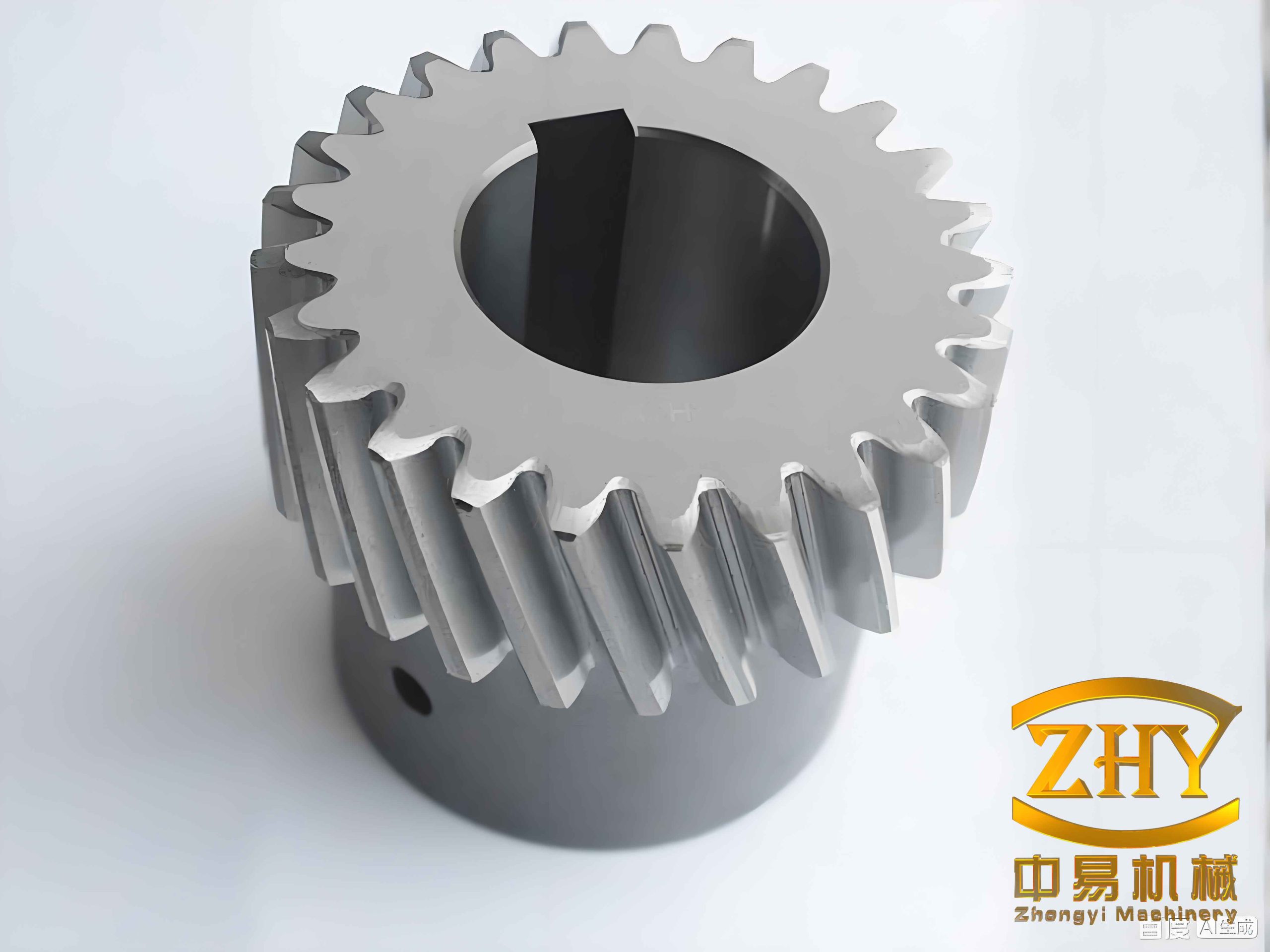
The following figure provides a conceptual illustration of a helical gear.
6. Conclusion
In this study, we presented a comprehensive analysis of the meshing characteristics of a helical gear pair used in a printing press. We proposed an improved potential energy method for calculating time-varying meshing stiffness. By integrating the Smith slicing theory and accounting for tooth root geometry and profile modification, we developed a more accurate and efficient analytical model. The key findings and contributions of our work are as follows:
1. Improved Meshing Stiffness Calculation: Our improved potential energy method calculates the meshing stiffness of a helical gear with a mean error of less than 5% compared to the ISO 6336-1 standard and FEA results. It overcomes the limitations of the traditional potential energy method, which fails to account for the tooth root curve, and provides results that are much closer to the actual stiffness values obtained from FEA. Critically, this method offers a significant improvement in computational efficiency over FEA, making it highly suitable for iterative design and dynamic analysis.
2. Dynamic Model and System Behavior: We developed a 9-DOF bending-torsion-axis coupled dynamic model for a printing press helical gear transmission system. The simulation results show that the dynamic meshing forces for both gear pairs (P-B and B-I) are nearly identical, averaging around 2700 N, which aligns well with the theoretical static force of 2832 N, thus validating our model.
3. Vibration Characteristics: Our analysis of vibration characteristics reveals distinct behavior for each helical gear:
- Radial Vibration: The blanket cylinder helical gear exhibits significantly lower radial vibration compared to the plate cylinder and impression cylinder helical gears. The latter two show similar radial vibration magnitudes but in opposite directions.
- Axial Vibration: The axial vibration of the blanket cylinder helical gear is the most critical finding. It is substantially larger than the axial vibrations of the plate and impression cylinder helical gears. This is a potential source of instability and print quality issues. The plate and impression cylinder gears exhibit similar, low-level axial vibrations in the same direction.
In conclusion, our improved potential energy method provides a fast, accurate, and effective tool for calculating the time-varying meshing stiffness of a helical gear. The subsequent dynamic analysis offers deep insights into the force and vibration behaviors of the helical gear transmission system in a printing press. These findings are invaluable for guiding gear design optimization, such as through profile modification or material selection, to suppress vibration, enhance operational stability, and improve print quality. The methodology and results presented here lay a solid theoretical foundation for the development of higher-performance, more reliable printing machinery and other systems employing helical gear transmissions.