
We present a comprehensive analytical method for calculating the instantaneous flow rate and displacement of involute external meshing helical gear pumps. The helical gear pump plays a crucial role in modern hydraulic systems due to its compact structure, high reliability, and low noise characteristics. However, the precise determination of its displacement and flow pulsation remains a challenge, especially when considering the complex meshing process involving both full-width and non-full-width contact zones. Traditional approaches often rely on simplified models or empirical corrections, leading to inaccuracies. In this study, we derive an exact closed-form solution based on gear meshing principles, involute tooth profile properties, and the relationship between instantaneous meshing point and rotation angle. We further apply the superposition principle by treating the helical gear as an infinite stack of infinitesimally thin spur gears, each shifted by a phase angle proportional to the helix angle. This yields a continuous integral expression for the instantaneous flow rate over the entire tooth width. The integration is performed separately for the non-full-width meshing region and the full-width meshing region. Finally, the displacement formula is obtained by integrating the instantaneous flow rate over one complete meshing cycle. To validate the proposed method, we conduct experiments on three commercial KF-series helical gear pumps with different geometric parameters. The theoretical predictions are compared with measured displacement values under controlled test conditions. The results demonstrate that the error between our calculated displacement and the actual measured displacement is less than 3%, and the deviation from the nominal displacement is within 2%. These accuracy levels significantly outperform traditional calculation methods, confirming the robustness and universality of our approach.
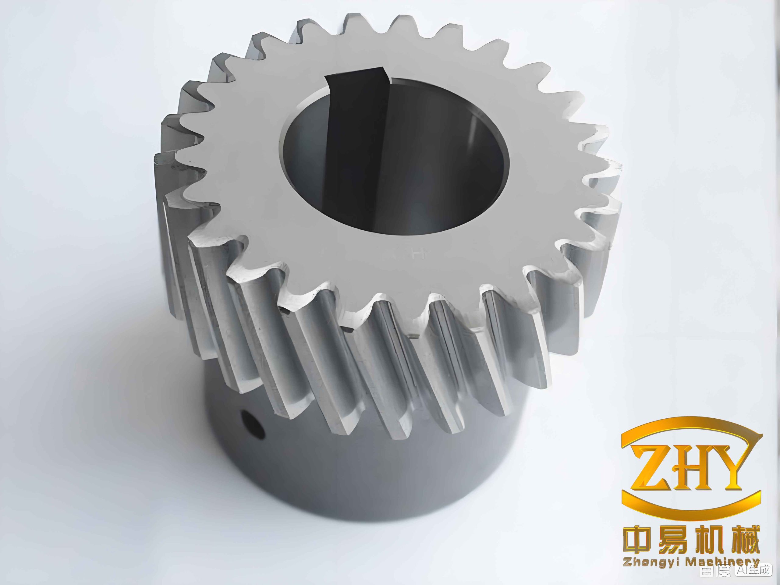
Our derivation starts from the fundamental energy conservation law for a gear pump. For a spur gear pump, the instantaneous flow rate is given by:
$$Q_{sh} = \frac{1}{2} B \omega \left[ (r_{a1}^2 – x^2) + (r_{a2}^2 – y^2) \frac{r_1}{r_2} \right]$$
where B is the gear width, ω the angular velocity, ra1 and ra2 the addendum radii of driving and driven gears, r1 and r2 the pitch radii, and x, y the distances from the meshing point to the gear centers. Using the involute tooth profile properties, we express x and y in terms of the rotation angle φ:
$$Q_{sh} = \frac{1}{2} B \omega \left\{ r_a^2 – \left[ \frac{r_b}{\cos(\arctan(\varphi + \tan\alpha’ – \pi/z))} \right]^2 \right\} + \frac{1}{2} B \omega \left\{ r_a^2 – \left[ \frac{r_b}{\cos(\arctan(\tan\alpha’ – \varphi + \pi/z))} \right]^2 \right\}$$
Here rb is the base radius, α’ the pressure angle at the pitch point, and z the number of teeth. This equation is the starting point for extending to helical gear pumps.
For a helical gear, we consider it as a continuum of infinitely thin spur gears stacked along the tooth width direction, each rotated by a phase angle proportional to its axial position. Let m be the distance from the reference end face. The local rotation angle is:
$$\varphi(m) = \theta \pm \frac{m \tan\beta}{R_w}$$
where β is the helix angle, Rw the pitch circle radius, and θ the rotation angle at the reference end face. The sign depends on the direction of rotation and helix orientation; it does not affect the final integral result. The instantaneous flow rate contributed by an infinitesimal slice dm is:
$$Q_{x\theta} = \frac{1}{2} \omega \left\{ r_a^2 – \left[ \frac{r_b}{\cos(\arctan(\theta + \frac{m \tan\beta}{R_w} + \tan\alpha’ – \pi/z))} \right]^2 \right\} dm + \frac{1}{2} \omega \left\{ r_a^2 – \left[ \frac{r_b}{\cos(\arctan(\tan\alpha’ + \pi/z – \theta – \frac{m \tan\beta}{R_w}))} \right]^2 \right\} dm$$
The total instantaneous flow rate of the helical gear pump is obtained by integrating over the entire meshing zone. Two distinct regions exist: the non-full-width meshing region where only part of the tooth width is engaged, and the full-width meshing region where the entire tooth width is in contact. The transition occurs when the rotation angle equals B tanβ / Rw. For the non-full-width region (0 ≤ φm ≤ B tanβ / Rw), the flow rate is:
$$Q_{sh1}’ = \frac{R_w}{\tan\beta} \int_0^{\varphi_m} \frac{1}{2} \omega \left\{ r_a^2 – \left[ \frac{r_b}{\cos(\arctan(\varphi – \varepsilon_n \pi / z + \tan\alpha’))} \right]^2 \right\} d\varphi + \frac{R_w}{\tan\beta} \int_0^{\varphi_m} \frac{1}{2} \omega \left\{ r_a^2 – \left[ \frac{r_b}{\cos(\arctan(\varepsilon_n \pi / z + \tan\alpha’ – \varphi))} \right]^2 \right\} d\varphi$$
where εn is the transverse contact ratio. For the full-width region (B tanβ / Rw ≤ φm ≤ 2εnπ / z), the integration is over the entire tooth width B:
$$Q_{sh2}’ = \int_0^B \frac{1}{2} \omega \left\{ r_a^2 – \left[ \frac{r_b}{\cos(\arctan(\theta_0 – \varepsilon_n \pi / z + \tan\alpha’))} \right]^2 \right\} dm + \int_0^B \frac{1}{2} \omega \left\{ r_a^2 – \left[ \frac{r_b}{\cos(\arctan(\tan\alpha’ – \theta_0 + \varepsilon_n \pi / z))} \right]^2 \right\} dm$$
The displacement of the helical gear pump, defined as the fluid volume expelled per revolution, is derived by integrating the instantaneous flow rate over one complete meshing cycle and multiplying by the number of teeth. Since at any instant there is always at least one pair of teeth in full-width contact (ignoring trapped oil effects), the displacement can be expressed as:
$$q = z \int_0^{2\pi/\omega} Q_{sh2}’ dt = \frac{z}{\omega} \int_0^{2\pi/z} d\theta_0 \int_0^B \frac{1}{2} \left\{ r_a^2 – \left[ \frac{r_b}{\cos(\arctan(\theta_0 – \pi/z + \tan\alpha’))} \right]^2 \right\} dm + \frac{z}{\omega} \int_0^{2\pi/z} d\theta_0 \int_0^B \frac{1}{2} \left\{ r_a^2 – \left[ \frac{r_b}{\cos(\arctan(\tan\alpha’ + \pi/z – \theta_0))} \right]^2 \right\} dm$$
This double integral simplifies to a practical form. For a helical gear pump with transverse contact ratio εn, the general displacement formula becomes:
$$V = z \int_0^{B\tan\beta/R_w} \frac{R_w}{\tan\beta} \left\{ \frac{1}{2} \left[ r_a^2 – \left( \frac{r_b}{\cos(\arctan(\varphi + \tan\alpha’ – \varepsilon_n \pi / z))} \right)^2 \right] + \frac{1}{2} \left[ r_a^2 – \left( \frac{r_b}{\cos(\arctan(\varepsilon_n \pi / z – \varphi + \tan\alpha’))} \right)^2 \right] \right\} d\varphi + z \int_{B\tan\beta/R_w}^{2\varepsilon_n \pi / z} \frac{R_w}{\tan\beta} \left\{ \frac{1}{2} \left[ r_a^2 – \left( \frac{r_b}{\cos(\arctan(\varphi + \tan\alpha’ – \varepsilon_n \pi / z))} \right)^2 \right] + \frac{1}{2} \left[ r_a^2 – \left( \frac{r_b}{\cos(\arctan(\varepsilon_n \pi / z – \varphi + \tan\alpha’))} \right)^2 \right] \right\} d\varphi$$
However, a more compact and practical expression is obtained by directly integrating the full-width meshing instantaneous flow over the period 2π/z, as the contribution from the non-full-width regions cancels out in the total displacement. The final displacement formula used in our validation is:
$$V_n = \frac{z}{\omega} \int_0^{2\pi/z} d\theta_0 \int_0^B \frac{1}{2} \left\{ r_a^2 – \left[ \frac{r_b}{\cos(\arctan(\theta_0 – \pi/z + \tan\alpha’))} \right]^2 \right\} dm + \frac{z}{\omega} \int_0^{2\pi/z} d\theta_0 \int_0^B \frac{1}{2} \left\{ r_a^2 – \left[ \frac{r_b}{\cos(\arctan(\tan\alpha’ + \pi/z – \theta_0))} \right]^2 \right\} dm$$
This integral can be evaluated analytically or numerically. In our study, we perform numerical integration using MATLAB for the given pump parameters.
To verify the accuracy of our derived displacement formula, we selected three commercial helical gear pumps of the KF series. Their geometric parameters are listed in Table 1.
| Parameter | KF112RF1-304D15 | KF125RF1-304D15 | KF150RF1-304D15 |
|---|---|---|---|
| Module (mm) | 4 | 4.75 | 4.75 |
| Number of teeth | 11 | 11 | 11 |
| Tooth width (mm) | 83 | 69 | 83 |
| Center distance (mm) | 47.5 | 57 | 57 |
| Addendum circle diameter (mm) | 56.13 | 66.8 | 66.8 |
| Helix angle (°) | 9 | 12.56 | 10.32 |
| Normal pressure angle (°) | 20 | 20 | 20 |
Experiments were conducted on a test rig as per the schematic described in the original paper. The oil temperature was controlled at 50±2°C, the system pressure was set to 0.2 MPa, and each pump was run continuously for over 5 minutes before recording data. The measured average displacement at nearly zero load is presented in Table 2.
| Parameter | KF112RF1-304D15 | KF125RF1-304D15 | KF150RF1-304D15 |
|---|---|---|---|
| Inlet temperature (°C) | 50.8 | 50.7 | 50.7 |
| Shaft speed (r/min) | 1493.3 | 1493.3 | 1493.3 |
| Outlet pressure (MPa) | 0.205 | 0.205 | 0.205 |
| Average displacement (mL/r) | 113.5 | 129.4 | 155.6 |
We then computed the displacement using our proposed formula (Equation 27) and compared it with the traditional formula from Li Zhuangyun, the nominal displacement provided by the manufacturer, and the measured data. The results are summarized in Table 3.
| Parameter | KF112RF1-304D15 | KF125RF1-304D15 | KF150RF1-304D15 |
|---|---|---|---|
| Nominal displacement (mL/r) | 112 | 125 | 150 |
| Traditional formula (mL/r) | 110.54 | 124.39 | 149.63 |
| Proposed formula (mL/r) | 111.5 | 126.4 | 152.08 |
| Measured displacement (mL/r) | 113.5 | 129.4 | 155.6 |
| Error (proposed vs measured) (%) | 1.76 | 2.3 | 2.26 |
| Error (proposed vs nominal) (%) | 0.45 | 1.12 | 1.39 |
From Table 3, we observe that our proposed displacement formula yields values that deviate from the nominal displacement by less than 2% and from the actual measured displacement by less than 3%. In contrast, the traditional formula underestimates the displacement for all three pumps and shows larger discrepancies. The consistency across different helix angles and tooth widths confirms the universality of our method. The small remaining errors can be attributed to manufacturing tolerances, oil temperature effects, and measurement uncertainties.
Furthermore, we used the derived instantaneous flow rate expressions to simulate the flow pulsation characteristics of the helical gear pump using MATLAB. The simulation clearly shows the two distinct stages of meshing: the non-full-width region where the flow rate gradually increases, and the full-width region where it remains constant (for a given rotation angle). This behavior is fundamentally different from spur gear pumps and explains the lower flow pulsation of helical gear pumps.
In conclusion, we have developed an accurate analytical method for calculating the displacement of involute external meshing helical gear pumps. By rigorously considering the helical gear’s three-dimensional meshing geometry and applying the superposition of infinitesimal spur gear slices, our method reproduces the actual displacement with high precision. The experimental validation on three different KF-series helical gear pumps demonstrates that the error does not exceed 3% relative to measured values and is within 2% of the nominal ratings. This work provides a reliable tool for the design, optimization, and performance evaluation of helical gear pumps in hydraulic applications. Future research can extend this methodology to include effects such as trapped oil volume, leakage, and variable pressure loads.