
In our modern electric vehicle powertrains, the two-stage helical gear transmission plays a pivotal role due to its high load capacity, smooth meshing, and excellent transmission efficiency. The dynamic behavior of such a system is significantly influenced by the meshing impact phenomenon, which arises from tooth deformation, manufacturing errors, and instantaneous changes in contact conditions. To ensure reliability and low noise, a thorough understanding of the meshing impact on the dynamics of helical gear systems is essential. In this work, we focus on a typical two-stage helical gear transmission used in electric vehicles and investigate its dynamic characteristics under various rotational speeds considering the meshing impact. We first derive the meshing impact force using an analytical approach, then establish a 16-degree-of-freedom (DOF) lumped-mass dynamic model that accounts for bending, torsional, and axial vibrations. The resulting set of differential equations is solved using the Runge-Kutta method. Detailed numerical results reveal how the meshing impact influences the acceleration along the meshing line for each gear pair, and how these effects propagate between stages. Our analysis provides valuable insights for the design and optimization of helical gear transmissions in electric vehicles.
1. Calculation of Meshing Impact Force
In helical gear transmissions, the meshing impact occurs at the instant when a pair of teeth start to engage (mesh-in impact) or leave (mesh-out impact). It is primarily caused by elastic deformation, geometric errors, and the transition between different contact states. Since mesh-in impact is generally more dominant in practice, we consider only the mesh-in impact in this study. The calculation of the mesh-in impact force follows the theory of line-of-action variation and equivalent mass method. We use the following steps:
First, the instantaneous moment of inertia Jn of the driving and driven gears (n = 1, 2) is given by:
$$ J_n = \pi \rho b \left( \frac{r_{bn}^4 – r_{hn}^4}{2} \right), \quad n = 1, 2 $$
where ρ is the gear material density, b is the tooth width, rbn is the base circle radius, and rhn is the hub hole radius.
The equivalent mass mn on the instantaneous meshing line is:
$$ m_n = \frac{J_n}{r_{bn}^2}, \quad n = 1, 2 $$
The kinetic energy Ek at the initial contact point is:
$$ E_k = \frac{1}{2} \cdot \frac{J_1 J_2}{J_1 r_{b2}’^2 + J_2 r_{b1}^2} \cdot v_s^2 $$
where rb2‘ is the instantaneous base circle radius of the driven gear during out-of-line meshing, and vs is the relative impact velocity.
The angle θ is determined geometrically as:
$$ \theta = \arccos\left( \frac{r_{b2}’}{r_{O_2 D}} \right) – \angle PO_2D – \alpha $$
Finally, the maximum mesh-in impact force Fs is expressed as:
$$ F_s = v_s \cdot \frac{J_1 J_2}{J_1 r_{b2}’^2 + J_2 r_{b1}^2} \left( q_s + \cos^2\theta \cdot q_q \right) $$
Here, qs is the single-tooth-pair compliance at the out-of-line initial contact point D, and qq is the combined compliance of all other tooth pairs except the impacting one. These compliances are obtained from the time-varying mesh stiffness and the corresponding load sharing factors. The parameters used for our specific two-stage helical gear transmission are listed in Table 1.
| Parameter | Gear 1 (Stage 1, driving) | Gear 2 (Stage 1, driven) | Gear 3 (Stage 2, driving) | Gear 4 (Stage 2, driven) |
|---|---|---|---|---|
| Helical direction | Left | Right | Left | Right |
| Module m (mm) | 4 | 4 | 4 | 4 |
| Number of teeth z | 23 | 80 | 22 | 87 |
| Pressure angle α (°) | 20 | 20 | 20 | 20 |
| Helix angle β (°) | 20 | 20 | 20 | 20 |
| Addendum ha (mm) | 4 | 4 | 4 | 4 |
| Dedendum hf (mm) | 5 | 5 | 5 | 5 |
| Tooth width b (mm) | 33 | 31.5 | 40 | 38 |
| Radial support stiffness (y,z) (N/m) | 2.0850×10⁹ | 1.8269×10⁹ | 1.8569×10⁹ | 2.3698×10⁹ |
| Axial support stiffness (x) (N/m) | 2.2159×10⁹ | 1.9949×10⁹ | 1.9949×10⁹ | 1.4097×10⁹ |
Using the above formulas and the parameters, we compute the mesh-impact forces for both gear pairs at three different input speeds (3000, 6000, and 12000 r/min). The results are summarized in Table 2.
| Input speed (r/min) | Gear pair 12 – Fs12 (N) | Gear pair 34 – Fs34 (N) |
|---|---|---|
| 3000 | 1245.94 | 89.21 |
| 6000 | 2419.89 | 178.41 |
| 12000 | 4983.77 | 357.21 |
It is evident that the impact force increases with rotational speed and that the first-stage gear pair (12) experiences significantly higher impact forces than the second-stage pair (34).
2. Dynamic Modeling of the Two-Stage Helical Gear Transmission
We adopt a lumped-mass approach to establish the dynamic model. The system consists of four helical gears (1,2,3,4) considered as rigid disks, supported by springs and dampers representing the bearings and the flexibility of shafts. The gear mesh is represented by time-varying stiffness and damping elements along the line of action. The model incorporates translational degrees of freedom in three orthogonal directions (x – axial, y – tangential, z – radial) and one rotational DOF about the gear axis. Thus, the total DOF is 4×4 = 16. The generalized displacement vector U is defined as:
$$ \mathbf{U} = [x_1, y_1, z_1, \phi_1, x_2, y_2, z_2, \phi_2, x_3, y_3, z_3, \phi_3, x_4, y_4, z_4, \phi_4]^T $$
where xi, yi, zi are the translational displacements of gear i, and φi is the rotational angle about its own axis.
The relative displacements δ12 and δ34 along the meshing line for gear pairs 12 and 34 are given by:
$$
\begin{aligned}
\delta_{12} =& (\phi_1 r_{b1} – \phi_2 r_{b2}) \cos\beta_{12} \\
&- (y_1 – y_2 + \Delta y_1 – \Delta y_2) \sin\zeta_{12} \cos\beta_{12} \\
&- (z_1 – z_2 + \Delta z_1 – \Delta z_2) \cos\zeta_{12} \cos\beta_{12} \\
&- (x_1 – x_2 + \Delta x_1 – \Delta x_2) \sin\beta_{12}
\end{aligned}
$$
$$
\begin{aligned}
\delta_{34} =& (\phi_3 r_{b3} – \phi_4 r_{b4}) \cos\beta_{34} \\
&+ (y_3 – y_4 + \Delta y_3 – \Delta y_4) \sin\zeta_{34} \cos\beta_{34} \\
&- (z_3 – z_4 + \Delta z_3 – \Delta z_4) \cos\zeta_{34} \cos\beta_{34} \\
&+ (x_3 – x_4 + \Delta x_3 – \Delta x_4) \sin\beta_{34}
\end{aligned}
$$
where rbi are base radii, β12, β34 are helix angles, ζ12, ζ34 are the angles between the meshing line and the z-axis, and Δxi, Δyi, Δzi are the mounting errors. The elastic and damping mesh forces are:
$$ P_{jk} = K_{jk} \delta_{jk}, \quad D_{jk} = C_{jk} \dot{\delta}_{jk} $$
and the total dynamic mesh force for pair jk is:
$$ F_{jk} = P_{jk} + D_{jk} $$
The time-varying mesh stiffness Kjk and damping Cjk are obtained using the method in the literature (e.g., using potential energy method or finite element results). The torsional coupling between stages is represented by an intermediate elastic shaft with stiffness K23 and damping C23.
The complete set of 16 dynamic equations is:
$$
\begin{aligned}
& M_1 \ddot{x}_1 + C_{x1} \dot{x}_1 + K_{x1} x_1 = F_{12} \sin\beta_{12} \\
& M_1 \ddot{y}_1 + C_{y1} \dot{y}_1 + K_{y1} y_1 = F_{12} \cos\beta_{12} \sin\zeta_{12} \\
& M_1 \ddot{z}_1 + C_{z1} \dot{z}_1 + K_{z1} z_1 = F_{12} \cos\beta_{12} \cos\zeta_{12} \\
& I_1 \ddot{\phi}_1 = T_1 – F_{12} \cos\beta_{12} r_{b1} – F_{s12} r_{b1} \\
& M_2 \ddot{x}_2 + C_{x2} \dot{x}_2 + K_{x2} x_2 = -F_{12} \sin\beta_{12} \\
& M_2 \ddot{y}_2 + C_{y2} \dot{y}_2 + K_{y2} y_2 = -F_{12} \cos\beta_{12} \sin\zeta_{12} \\
& M_2 \ddot{z}_2 + C_{z2} \dot{z}_2 + K_{z2} z_2 = -F_{12} \cos\beta_{12} \cos\zeta_{12} \\
& I_2 \ddot{\phi}_2 + C_{23}(\dot{\phi}_2 – \dot{\phi}_3) + K_{23}(\phi_2 – \phi_3) = F_{12} \cos\beta_{12} r_{b2} + F_{s12} r_{b2} \\
& M_3 \ddot{x}_3 + C_{x3} \dot{x}_3 + K_{x3} x_3 = -F_{34} \sin\beta_{34} \\
& M_3 \ddot{y}_3 + C_{y3} \dot{y}_3 + K_{y3} y_3 = -F_{34} \cos\beta_{34} \sin\zeta_{34} \\
& M_3 \ddot{z}_3 + C_{z3} \dot{z}_3 + K_{z3} z_3 = F_{34} \cos\beta_{34} \cos\zeta_{34} \\
& I_3 \ddot{\phi}_3 + C_{23}(\dot{\phi}_3 – \dot{\phi}_2) + K_{23}(\phi_3 – \phi_2) = -F_{34} \cos\beta_{34} r_{b3} + F_{s34} r_{b3} \\
& M_4 \ddot{x}_4 + C_{x4} \dot{x}_4 + K_{x4} x_4 = F_{34} \sin\beta_{34} \\
& M_4 \ddot{y}_4 + C_{y4} \dot{y}_4 + K_{y4} y_4 = F_{34} \cos\beta_{34} \sin\zeta_{34} \\
& M_4 \ddot{z}_4 + C_{z4} \dot{z}_4 + K_{z4} z_4 = -F_{34} \cos\beta_{34} \cos\zeta_{34} \\
& I_4 \ddot{\phi}_4 = F_{34} \cos\beta_{34} r_{b4} + F_{s34} r_{b4} – T_4
\end{aligned}
$$
where T1 = 100 N·m is the input torque, T4 is the output torque, Mi and Ii are mass and moment of inertia of gear i, Kxi, Kyi, Kzi and Cxi, Cyi, Czi are support stiffness and damping. The mesh impact forces Fs12 and Fs34 are included as additional excitations on the rotational DOFs. To avoid rigid-body displacement and improve numerical conditioning, we eliminate the rigid-body mode and perform dimensionless normalization before solving. The fourth-order Runge-Kutta method is employed to integrate the equations. After obtaining the accelerations, the acceleration along the meshing line for each gear pair is computed as:
$$
\begin{aligned}
a_{12} =& [(\ddot{\phi}_1 r_{b1} – \ddot{\phi}_2 r_{b2}) – (\ddot{y}_1 – \ddot{y}_2)\sin\zeta_{12} – (\ddot{z}_1 – \ddot{z}_2)\cos\zeta_{12}] \cos\beta_{12} \\
&- (\ddot{x}_1 – \ddot{x}_2)\sin\beta_{12} \\
a_{34} =& [(\ddot{\phi}_3 r_{b3} – \ddot{\phi}_4 r_{b4}) – (\ddot{y}_3 – \ddot{y}_4)\sin\zeta_{34} – (\ddot{z}_3 – \ddot{z}_4)\cos\zeta_{34}] \cos\beta_{34} \\
&+ (\ddot{x}_3 – \ddot{x}_4)\sin\beta_{34}
\end{aligned}
$$
3. Numerical Results and Discussion
We simulate the system at three input speeds: 3000, 6000, and 12000 r/min. The input torque is constant at 100 N·m. The mesh impact forces used in the model are those listed in Table 2. The time-domain accelerations along the meshing line for both gear pairs are extracted. The peak values of acceleration in the mesh-impact regions are summarized in Table 3.
| Input speed (r/min) | Gear pair 12 – a12 (m/s²) | Gear pair 34 – a34 (m/s²) |
|---|---|---|
| 3000 | 686.21 | 223.35 |
| 6000 | 1135.75 | 500.58 |
| 12000 | 2291.61 | 1131.77 |
From these results, several important observations can be made. First, as the speed increases, the acceleration peaks for both helical gear pairs increase significantly. At 3000 r/min, the impact region of gear pair 12 shows an acceleration of 686.21 m/s², while at 12000 r/min it reaches 2291.61 m/s². This indicates that higher rotational speeds amplify the meshing impact effect and lead to more severe vibration in the helical gear transmission. The growth is nonlinear and more pronounced for the first-stage pair. Second, at any given speed, the acceleration of gear pair 12 is consistently larger than that of gear pair 34. For example, at 12000 r/min, a12 = 2291.61 m/s² is nearly double a34 = 1131.77 m/s². This is attributed to the higher mesh impact force in the input stage (Fs12 ≫ Fs34) and the fact that the input shaft rotates faster, resulting in stronger dynamic excitation.
Another important aspect is the mutual influence between the two stages. When comparing the time-domain signals, we observe that at low speed (3000 r/min), the impact of gear pair 34 on the acceleration of gear pair 12 is negligible. However, the impact of gear pair 12 on gear pair 34 is clearly visible: the high-frequency oscillations from the first stage modulate the response of the second stage. At higher speeds, this interaction becomes more intense, and the vibration of each pair carries signatures of the other’s meshing frequency. Specifically, the frequency of the influence coincides with the meshing frequency of the influencing gear pair. For instance, the acceleration of gear pair 34 exhibits components at the meshing frequency of gear pair 12, and vice versa. This cross-stage coupling is a key characteristic of multi-stage helical gear systems and must be considered in noise and vibration analysis.
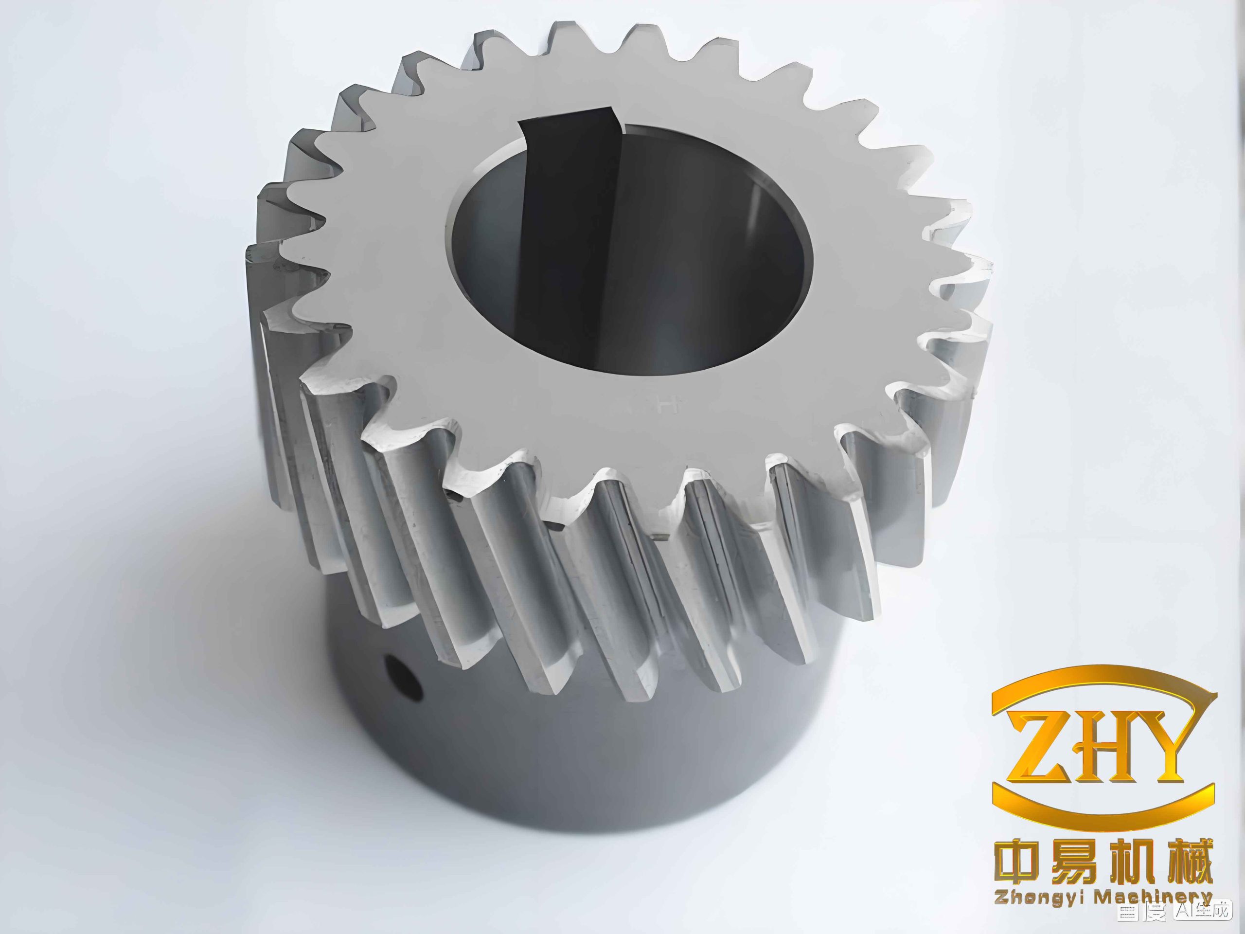
To visualize the dynamic behavior, a typical helical gear set is shown below. The helical profile ensures gradual engagement and reduces noise compared to spur gears, but the axial force component and the impact at the beginning of contact remain important design challenges.
The mesh impact not only increases the peak acceleration but also introduces broadband excitation that may excite resonances in the supporting structure. Our analysis shows that the stage-1 helical gear pair plays a dominant role in the overall dynamic response, and any design modifications (such as profile relief or crowning) should prioritize the input pair to mitigate the impact. Furthermore, since the mesh impact force scales almost linearly with speed (see Table 2), reducing the input speed or using a higher gear ratio can effectively lower the impact severity. However, speed is often a design constraint for performance, so other measures such as optimizing the helix angle or using vibration absorbers might be necessary.
4. Conclusions
In this work, we have systematically studied the dynamic characteristics of a two-stage helical gear transmission for electric vehicles under the influence of mesh impact. The main conclusions are:
1) The mesh impact force increases with rotational speed, and the input-stage helical gear pair (pair 12) experiences much larger impact forces than the output-stage pair (pair 34). Consequently, the acceleration peaks in the meshing line direction rise significantly with speed, and the input-stage pair contributes more to system vibration.
2) At the same operating speed, the mesh impact from the first stage has a stronger influence on the second stage than the reverse. The mutual coupling between stages occurs at frequencies corresponding to the meshing frequency of each pair. This indicates that dynamic interactions in multi-stage helical gear systems are not negligible and should be included in the design phase.
3) The established 16-DOF model, together with the analytical mesh impact force, provides a reliable tool to predict the vibration behavior of two-stage helical gear transmissions. The parametric study highlights the importance of considering mesh impact excitation in the early design stage to avoid resonance and excessive noise.
Future work will extend this analysis to include tooth profile modifications, variable load conditions, and experimental validation to further enhance the accuracy and applicability of the model for electric vehicle helical gear transmissions.