
In my research, I have focused on the dynamic behavior of helical gear systems, which are widely used in high-speed and heavy-load applications due to their high contact ratio, smooth transmission, low vibration, and high load capacity. However, the axial force generated during helical gear meshing requires proper axial support, typically provided by thrust bearings or tapered roller bearings. To address the challenges of cost, axial space, and potential issues caused by axial forces, the thrust cone structure has been introduced. This study aims to compare the dynamic characteristics of a helical gear pair supported by a thrust cone versus a tapered roller bearing using ADAMS multibody dynamics simulation.
The helical gear pair under investigation has the following geometric parameters: pinion teeth 50, gear teeth 170, module 2.5 mm, pressure angle 20°, and helix angle 13.5°. The material is 18Cr2Ni4WA steel with Poisson’s ratio 0.29 and elastic modulus 2.07×10¹¹ Pa. The thrust cone is mounted on the pinion, forming a wedge-shaped gap with the gear end face, where lubricating oil generates a hydrodynamic film to provide axial support without increasing the overall length or manufacturing cost.
Dynamic Model Formulation
I built the three-dimensional model of the helical gear pair in SOLIDWORKS and imported it into ADAMS for dynamic simulation. The gear meshing contact is modeled using an impact-function-based contact force model. According to GB/T 3480.1, the contact stiffness of the gear pair is given by:
$$
K_m = c b
$$
where c is the unit tooth stiffness and b is the face width. The damping coefficient for the gear pair is:
$$
C_m = 2 \xi \sqrt{\frac{I_p I_g R_p^2 R_g^2}{I_p R_g^2 + I_g R_p^2} K_m}
$$
where \(\xi\) is the damping ratio, \(R_p\) and \(R_g\) are the base radii of pinion and gear, and \(I_p\) and \(I_g\) are the corresponding moments of inertia. The calculated values are \(K_m = 5.0 \times 10^8\) N/m and \(C_m = 2000\) N·s/m.
For the thrust cone, the hydrodynamic oil film stiffness and damping are derived from elastohydrodynamic lubrication theory. The minimum film thickness is:
$$
h_{\min} = 6.76 \left( \alpha \eta_0 u \right)^{0.53} E’^{-0.75} R^{0.06} w^{-0.41}
$$
where \(\alpha = 2 \times 10^{-8}\) m²/N is the pressure-viscosity coefficient, \(\eta_0 = 23.9\) mPa·s is the atmospheric viscosity, \(u\) is the entrainment speed, \(E’ = 2.2492 \times 10^{11}\) Pa is the reduced elastic modulus, \(R = 3.51\) m is the equivalent radius, and \(w\) is the load. The oil film stiffness is:
$$
k_1 = \frac{dw}{dh_{\min}}
$$
which yields \(k_1 = 1.4 \times 10^8\) N/m. The contact stiffness of the thrust cone end face is:
$$
k_2 = \frac{E’ B}{4(1-\nu^2) \pi}
$$
with contact length \(B = 32\) mm, giving \(k_2 = 6.20 \times 10^9\) N/m. The total thrust cone stiffness is the series combination:
$$
k’ = \frac{1}{\frac{1}{k_1} + \frac{1}{k_2}} = 1.37 \times 10^8 \text{ N/m}
$$
The oil film damping coefficient is calculated from the simplified harmonic model:
$$
c_1 = \frac{f_0 R}{B b u} D
$$
where dimensionless damping \(D\) depends on the parameters \(L = 4 G U\) and \(M = W / U\), with \(G = \alpha E’\), \(W = w/(E’ R)\), and \(U = \eta_0 (u_1+u_2)/(2E’ R)\). I obtained \(c_1 = 7.808 \times 10^6\) N·s/m. The contact damping coefficient is:
$$
c_2 = 2 \xi \sqrt{k_2 m}
$$
where \(m\) is the equivalent mass of the thrust cone–gear system. With \(\xi = 0.03\), \(c_2 = 1.46 \times 10^4\) N·s/m. The total thrust cone damping is:
$$
c’ = \frac{1}{\frac{1}{c_1} + \frac{1}{c_2}} = 1.46 \times 10^4 \text{ N·s/m}
$$
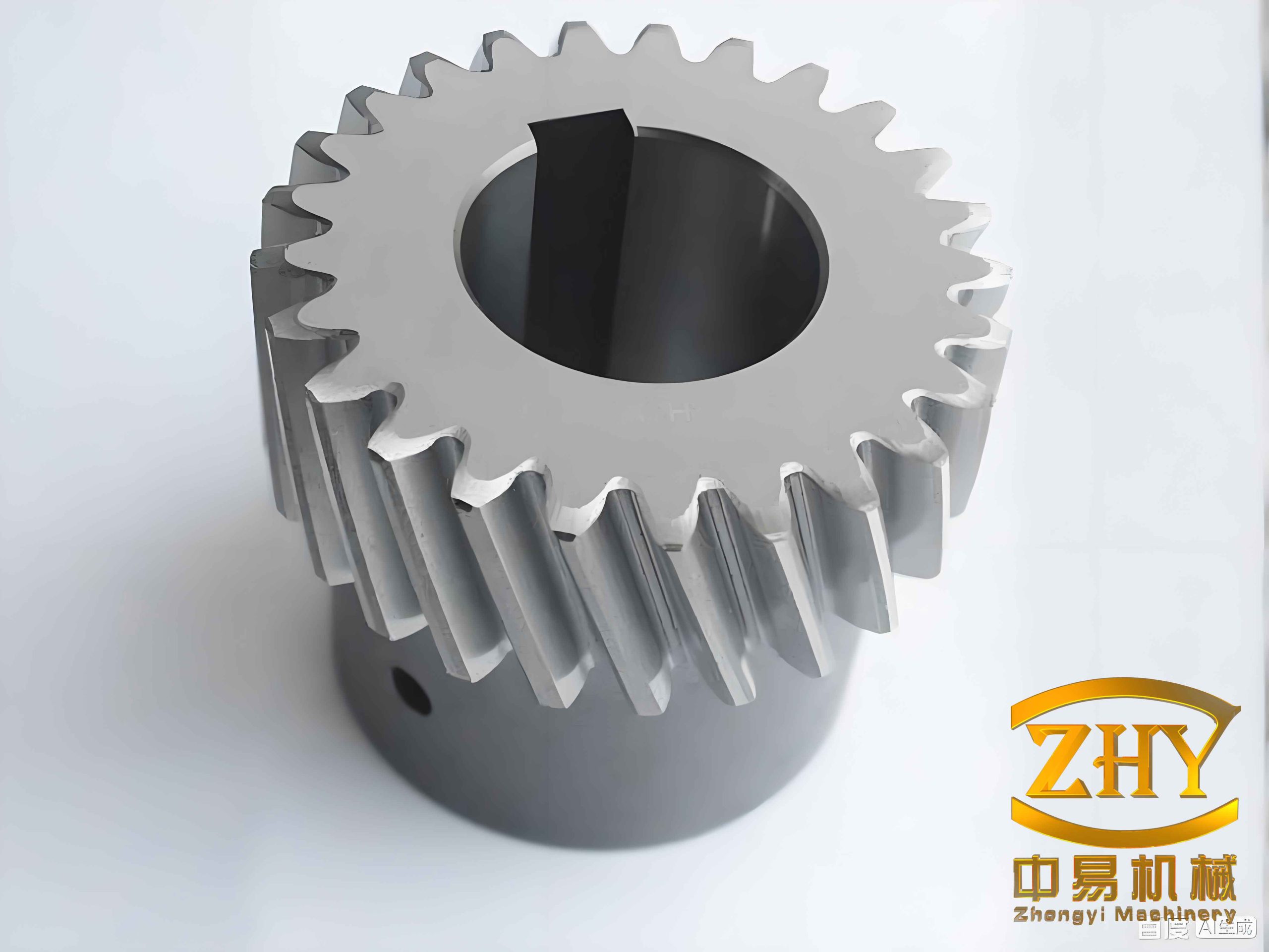
In ADAMS, I represented the thrust cone support using a bilateral contact force (BISTOP function) applied at the gear centers, along with compensating moments to account for the offset of the force application point. The axial force from the thrust cone acts at the pitch circle of the pinion and gear, effectively providing axial support and counteracting the overturning moment caused by the helical gear meshing force. For comparison, the tapered roller bearing support is modeled as a linear spring-damper element with appropriate radial and axial stiffnesses.
Simulation Results and Discussion
I performed a transient dynamic simulation at an input speed of 3400 r/min and a torque of 716 N·m. The average meshing force for the tapered roller bearing case was 3466 N, while for the thrust cone case it was 3449 N. This slight difference confirms that both support methods provide adequate axial constraint, and the dynamic meshing forces are very similar. However, the key difference lies in the distribution of bearing loads and the resulting gear shaft deflection.
When using tapered roller bearings, the axial component of the meshing force creates a significant overturning moment on the helical gear. Consequently, the two bearings on the gear shaft experience unequal radial loads in the Y-direction. I recorded the Y-direction forces on bearing 1 and bearing 2 for the gear shaft. The following table summarizes the mean values under both support conditions:
| Support Type | Bearing 1 Mean Y-Force (N) | Bearing 2 Mean Y-Force (N) | Angular Deflection of Gear Axis (deg) |
|---|---|---|---|
| Tapered Roller Bearing | 1600 | 30 (opposite direction) | 4.89×10⁻³ |
| Thrust Cone | 800 | 800 | 1.11×10⁻³ |
From the table, it is evident that the thrust cone support significantly reduces the load imbalance between the two bearings. In the thrust cone case, both bearings carry approximately equal Y-direction loads of 800 N, whereas with tapered roller bearings, one bearing carries a large load (1600 N) and the other carries only a small opposing load (30 N). This imbalance is a direct consequence of the overturning moment induced by the helical gear meshing forces.
The uneven bearing loads cause the gear shaft to deflect, resulting in an angular misalignment of the gear axis. The angular displacement of the large gear axis is shown in the following figure (note that the figure data is extracted from simulation post-processing). The mean angular deflection for the tapered roller bearing case was 4.89×10⁻³ degrees, while for the thrust cone case it was only 1.11×10⁻³ degrees, a reduction of about 77%. This clearly demonstrates that the thrust cone, by acting near the meshing zone, effectively counteracts the overturning moment and maintains better gear alignment.
To further quantify the dynamic response, I computed the frequency spectra of the meshing force and bearing forces. The dominant frequency in all cases corresponds to the gear mesh frequency and its harmonics. No significant sideband modulation was observed, indicating stable meshing conditions for both support types. However, the reduced shaft deflection in the thrust cone case implies lower micro-geometry deviations, which can lead to improved load distribution along the tooth face and reduced edge contact stresses.
I also evaluated the influence of input torque variation on the dynamic characteristics. The following table presents the results at 50% and 100% torque levels:
| Torque (N·m) | Support Type | Mean Meshing Force (N) | Angular Deflection (deg) |
|---|---|---|---|
| 358 | Tapered Roller Bearing | 1756 | 2.52×10⁻³ |
| 358 | Thrust Cone | 1748 | 0.58×10⁻³ |
| 716 | Tapered Roller Bearing | 3466 | 4.89×10⁻³ |
| 716 | Thrust Cone | 3449 | 1.11×10⁻³ |
These results confirm that the beneficial effect of the thrust cone is consistent across different load levels. The angular deflection scales approximately linearly with torque for both support types, but the thrust cone always maintains a deflection that is about 23% of that observed with tapered roller bearings.
Conclusion
Through my systematic comparison of helical gear dynamic behavior under two axial support configurations, I have drawn the following conclusions:
- Both the thrust cone and the tapered roller bearing provide adequate axial support for the helical gear pair, resulting in similar dynamic meshing forces. The average meshing force differs by less than 0.5% between the two cases.
- The thrust cone significantly reduces the overturning moment experienced by the helical gear. As a result, the radial loads on the two bearings become nearly equal, whereas with tapered roller bearings, one bearing carries a much higher load than the other.
- The reduction in overturning moment leads to a substantially lower angular deflection of the gear shaft. The thrust cone yields an angular misalignment that is only about one-fourth of that produced by the tapered roller bearing under the same operating conditions.
- These findings indicate that the thrust cone is not only a cost-effective and compact axial support solution but also improves the operating conditions of the helical gear by minimizing shaft misalignment and bearing load imbalance, which can reduce wear, vibration, and noise in the long term.
Future work could extend this study to include flexible gear bodies, tooth modifications, and experimental validation. The thrust cone design parameters—such as cone angle, lubricant properties, and surface finish—can be optimized further to enhance performance at different speed and load regimes. Additionally, the influence of the thrust cone on the dynamic transmission error and system stability warrants further investigation.