
In the field of mechanical transmission, helical gears are widely utilized due to their smooth engagement, high load capacity, and low noise characteristics. However, the presence of the helix angle in helical gears introduces a unique challenge when using machine vision for dimensional inspection: the helix angle inevitably creates shadow regions on the captured end-face image, leading to reduced measurement accuracy. To address this issue, we have developed an improved measurement scheme that employs a high-resolution dual telecentric lens combined with a close-range backlight source. By integrating Otsu’s image binarization method, we obtain an ideal end-face image of the helical gear. Furthermore, we propose a novel contour feature point method that extracts intersection points between lines connecting the gear center with each tooth centroid and the tooth tip contour, as well as intersection points between lines rotated by a certain angle and the tooth root contour. These points are then used for circle fitting to determine the gear parameters. Experimental results demonstrate that the absolute measurement error remains within 0.02 mm, confirming the high accuracy of our approach.
Introduction to Helical Gear Measurement Challenges
Helical gears are essential components in many industrial applications, such as automotive transmissions, aerospace drives, and precision machinery. Their geometric accuracy directly influences the performance and lifespan of the entire mechanical system. Traditional contact-based measurement methods, such as coordinate measuring machines (CMM) and gear testers, offer high accuracy but are often slow, expensive, and unsuitable for online inspection. In contrast, machine vision-based methods provide non-contact, rapid, and cost-effective solutions. However, when measuring helical gears, the helix angle causes the tooth flanks to be partially captured in the end view, creating shadow artifacts that distort the true boundary of the gear end face. This shadowing effect complicates image segmentation and edge detection, leading to significant errors in parameter estimation.
Several researchers have attempted to overcome this problem. Some have applied gamma correction or global low-light enhancement before binarization, but these methods may sacrifice image details. Others have used adaptive thresholding, but the results are inconsistent for gears with different helix angles and lighting conditions. Our work focuses on a systematic approach combining optical hardware optimization and robust image processing algorithms to eliminate shadow effects and accurately measure the tooth tip diameter, root diameter, and tooth count of helical gears.
Design of the Visual Measurement System
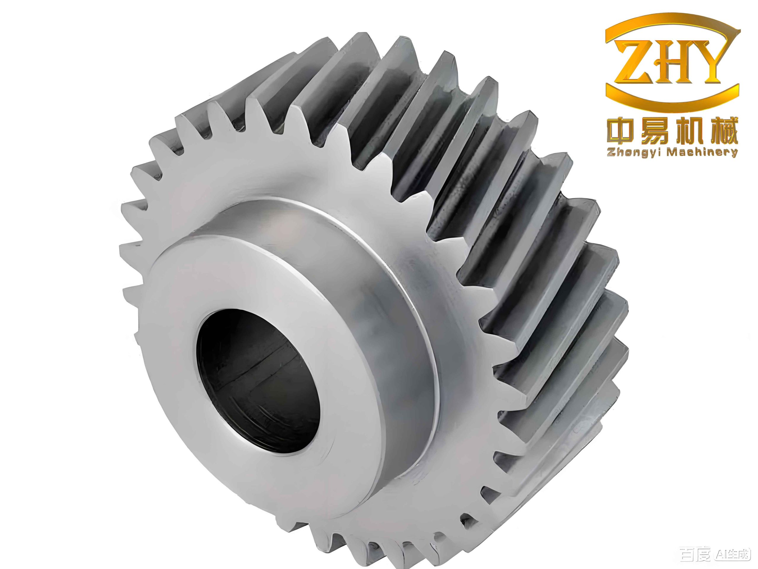
The measurement object is a helical cylindrical gear, as shown conceptually in the figure above. The required parameters include the number of teeth Z, the tip circle diameter da, and the root circle diameter df. The measurement accuracy target is set to 0.02 mm. To achieve this, we designed a dedicated vision measurement setup comprising an industrial area-scan camera with a resolution of 4024 × 3036 pixels, a dual telecentric lens with low distortion and a large field of view, and a white LED backlight source. The dual telecentric lens ensures that the magnification remains constant regardless of the object distance within a certain range, which is critical for accurate dimensional measurement.
We compared two backlight configurations: a distant backlight and a close-range backlight. Under the distant backlight, the acquired image exhibited severe shadow regions along the tooth flanks, as typical for helical gears. In contrast, by placing the backlight source very close to the gear (close-range backlight), the shadow area was substantially reduced, and the contrast between the gear body and the background was significantly enhanced. Therefore, we adopted the close-range backlight configuration for all subsequent experiments.
The measurement system flow consists of three main modules: optimal exposure image acquisition, image processing, and parameter measurement. In the first module, we automatically search for the optimal exposure time range by varying the exposure time in steps (ΔT = 1000 ms) starting from an initial value T0, while keeping the light intensity constant at level 30. The system captures images at each exposure step and evaluates the image quality to determine the best exposure interval. The second module performs grayscale conversion, bilateral filtering, Otsu binarization, and edge detection. The third module implements the proposed contour feature point method to extract the tip and root circles.
Image Processing for Helical Gears
Grayscale Transformation
The raw image from the camera is an RGB color image containing three channels. Since only grayscale information is needed for edge detection, we convert the color image to grayscale using the weighted average method:
$$
Gray(i,j) = 0.299 \times R(i,j) + 0.587 \times G(i,j) + 0.114 \times B(i,j)
$$
where (i, j) denotes the pixel coordinates, and R, G, B are the corresponding channel values. This transformation reduces computational complexity while preserving sufficient contrast between the gear and the background.
Bilateral Filtering for Noise Reduction
To suppress noise without blurring strong edges, we apply bilateral filtering, which combines spatial proximity and intensity similarity. The filtering operation is defined as:
$$
h(i,j) = \frac{\sum_{k,l} f(k,l) w_s(k,l) w_r(k,l)}{\sum_{k,l} w_s(k,l) w_r(k,l)}
$$
$$
w_s(k,l) = \exp\left(-\frac{(i-k)^2 + (j-l)^2}{2\sigma_s^2}\right)
$$
$$
w_r(k,l) = \exp\left(-\frac{\|f(i,j) – f(k,l)\|^2}{2\sigma_r^2}\right)
$$
where f(k,l) is the input pixel value, h(i,j) is the filtered output, σs and σr are the spatial and range standard deviations, respectively. We empirically set σs = 3 and σr = 30, which effectively removes Gaussian noise while preserving the sharp edges of the helical gear teeth.
Otsu Binarization
For binarization, we employ Otsu’s method, which automatically selects an optimal threshold T by maximizing the inter-class variance between foreground (gear) and background. Otsu’s algorithm is particularly robust because it is fully automatic and works well even when the histogram is bimodal. After thresholding, the resulting binary image may contain small noise regions (e.g., isolated pixels). We use the morphological operation “select_shape” to remove connected components with area smaller than a predefined threshold, leaving only the main gear region. This step is crucial for helical gears because residual shadow fragments can otherwise persist as small blobs.
Edge Detection
To obtain sub-pixel accuracy, we use an edge detection operator called ‘edges_sub_pix’, which fits a Gaussian edge model to the intensity profile. This yields edge points with sub-pixel coordinates. Subsequently, we apply ‘select_shape_xld’ to extract the outer contour of the gear, which is a continuous curve representing the boundary of the end face.
Parameter Measurement Using Contour Feature Points
We propose a novel method named the contour feature point method to measure the tip circle diameter and root circle diameter of helical gears. The procedure involves three main steps:
Step 1: Tooth Count and Centroid Extraction
First, we obtain the minimum circumscribed circle and maximum inscribed circle of the gear outer contour. Using these two circles, we compute their average diameter and create a circular mask of that diameter. The difference between the gear region and this mask yields the tooth region (the protrusions). The number of connected components in the tooth region equals the number of teeth Z. For each tooth, we compute its centroid coordinates (xc,k, yc,k) for k = 1, 2, …, Z.
Step 2: Gear Center Determination
We measure the inner bore (shaft hole) of the gear using a caliper tool (a rectangular measurement region of length 50 pixels and width 1 pixel, placed 180 times around the bore). The center of the fitted circle to the bore points is taken as the gear center (x0, y0).
Step 3: Extraction of Tip and Root Points
For each tooth centroid, we draw a line from the gear center to the centroid and extend it outward until it intersects the outer gear contour. However, due to slight irregularities, we actually consider a small angular range: we rotate the line by ±1° and take the intersection points in that neighborhood. These intersection points lie on the tooth tip. We collect all such points from all teeth, and then perform a least-squares circle fit to obtain the tip circle diameter da.
For the root circle, we start from the same line (gear center to tooth centroid) and rotate it clockwise by an angle of π/(2Z) radians. This rotated line is then extended outward to intersect the gear contour. The intersection points lie on the tooth root (the valley between teeth). Again, we collect points from all teeth and fit a least-squares circle to obtain the root circle diameter df.
The least-squares circle fitting minimizes the sum of squared radial distances:
$$
\min_{a,b,R} \sum_{i=1}^{N} \left(\sqrt{(x_i – a)^2 + (y_i – b)^2} – R\right)^2
$$
where (a,b) is the center and R is the radius. We use an algebraic fitting method for efficiency.
Experimental Setup and Results
Optimal Exposure Time Determination
To find the best exposure range, we fixed the helical gear sample and the lighting intensity (level 30). Starting from 24,000 ms, we increased the exposure time in steps of 1,000 ms up to 38,000 ms. For each exposure, we captured an image and measured the tip and root diameters using the proposed method. The absolute errors (measured value minus nominal value) for both diameters are plotted against exposure time. The results clearly indicate that the minimum errors occur in the range of 26,000 to 32,000 ms. Outside this interval, either underexposure or overexposure leads to significant deviation. Therefore, all subsequent measurements were taken with an exposure time of 28,000 ms.
Comparative Measurement Results
We compared our contour feature point method with the traditional method described in reference [12] (which uses minimum circumscribed circle for tip and maximum inscribed circle for root). Both methods were applied to the same helical gear with nominal tip diameter 44.19 mm and nominal root diameter 35.19 mm. The gear had a helix angle of 15°, module 1.5, and 12 teeth. Ten repeated measurements were performed, and the averages are summarized in Table 1.
| Parameter | Nominal Value | Reference [12] Measured | Absolute Error (Ref [12]) | Our Method Measured | Absolute Error (Ours) |
|---|---|---|---|---|---|
| Tip diameter da | 44.19 | 44.3077 | 0.1177 | 44.1716 | 0.0184 |
| Root diameter df | 35.19 | 35.0860 | 0.1040 | 35.2076 | 0.0176 |
As shown, the traditional method overestimates the tip diameter and underestimates the root diameter, mainly because the min/max circumscribed circles are sensitive to contour outliers (e.g., burrs or shadow-induced false edges). In contrast, our contour feature point method only uses points at the exact tooth tip and root centers, which are less affected by local defects. The absolute errors are both well below 0.02 mm, meeting the required accuracy.
To further validate the generalizability of our method, we tested it on a standard spur gear (module 2, 18 teeth) with nominal tip diameter 40 mm and root diameter 31 mm. The results are given in Table 2.
| Parameter | Nominal Value | Reference [12] Measured | Absolute Error (Ref [12]) | Our Method Measured | Absolute Error (Ours) |
|---|---|---|---|---|---|
| Tip diameter da | 40.00 | 40.0904 | 0.0904 | 40.0159 | 0.0159 |
| Root diameter df | 31.00 | 30.9025 | 0.0975 | 30.9846 | 0.0154 |
Again, our method achieves absolute errors within 0.02 mm, while the reference method shows errors close to 0.1 mm. This indicates that the contour feature point method is robust and accurate not only for helical gears but also for standard spur gears.
Discussion on the Influence of Helix Angle
The success of our method relies heavily on the effective removal of shadow regions caused by the helix angle of helical gears. The close-range backlight source minimizes the amount of scattered light from the tooth flanks, and Otsu binarization further separates the true gear region from residual shadows. Additionally, by using the line connecting the gear center to the tooth centroid, we naturally avoid the shadow-contaminated areas near the tooth edges. The rotation angle π/(2Z) for the root points ensures that we sample the deepest part of the tooth space, which is less influenced by the helix angle-induced distortion.
In theory, for helical gears with very large helix angles (e.g., >30°), the shadow might be more pronounced, but our experiments with a 15° helix angle showed excellent results. Further studies could explore the upper limit of the helix angle for which the proposed method remains reliable.
Conclusion
In this paper, we have presented a comprehensive machine vision-based method for measuring the profile parameters of helical gears. The key contributions are as follows:
- An optimized illumination and optical setup using a close-range backlight and a dual telecentric lens that significantly reduces shadow artifacts associated with the helix angle of helical gears.
- A robust image processing pipeline incorporating bilateral filtering and Otsu binarization to obtain clean binary images of the gear end face.
- A novel contour feature point method that precisely locates the tooth tip and root points by connecting the gear center with tooth centroids and applying a small angular rotation. This method avoids the pitfalls of global min/max circumscribed circles and achieves high accuracy.
- Experimental validation on both helical and spur gears demonstrates that the absolute measurement errors for tip and root diameters are consistently within 0.02 mm, meeting the stringent requirements for industrial inspection.
Future work will focus on extending the method to measure additional parameters such as the helix angle itself, tooth thickness, and pitch error. Furthermore, we aim to develop a dedicated real-time inspection system that can be integrated into production lines for helical gear manufacturing.
Acknowledgment
We gratefully acknowledge the support of our laboratory facilities and the valuable discussions with colleagues. The helical gear sample used in the experiments was manufactured by a local precision gear factory.