
I present a comprehensive investigation into the impact excitation mechanism of high-speed and heavy-load involute helical gear pairs. In modern aerospace, marine, wind power, and high-speed train applications, helical gears are preferred because of their smooth transmission, high load capacity, and convenient manufacturing adjustment. However, under high-speed and heavy-load conditions, the gear teeth experience large deformation and elevated tooth surface temperatures, which intensify impact excitation, alter the contact state, and even lead to tooth disengagement or breakage. My work aims to clarify the generation mechanism and influencing factors of impact excitation in helical gear pairs, thereby providing a theoretical basis for reducing tooth breakage faults and transient noise.
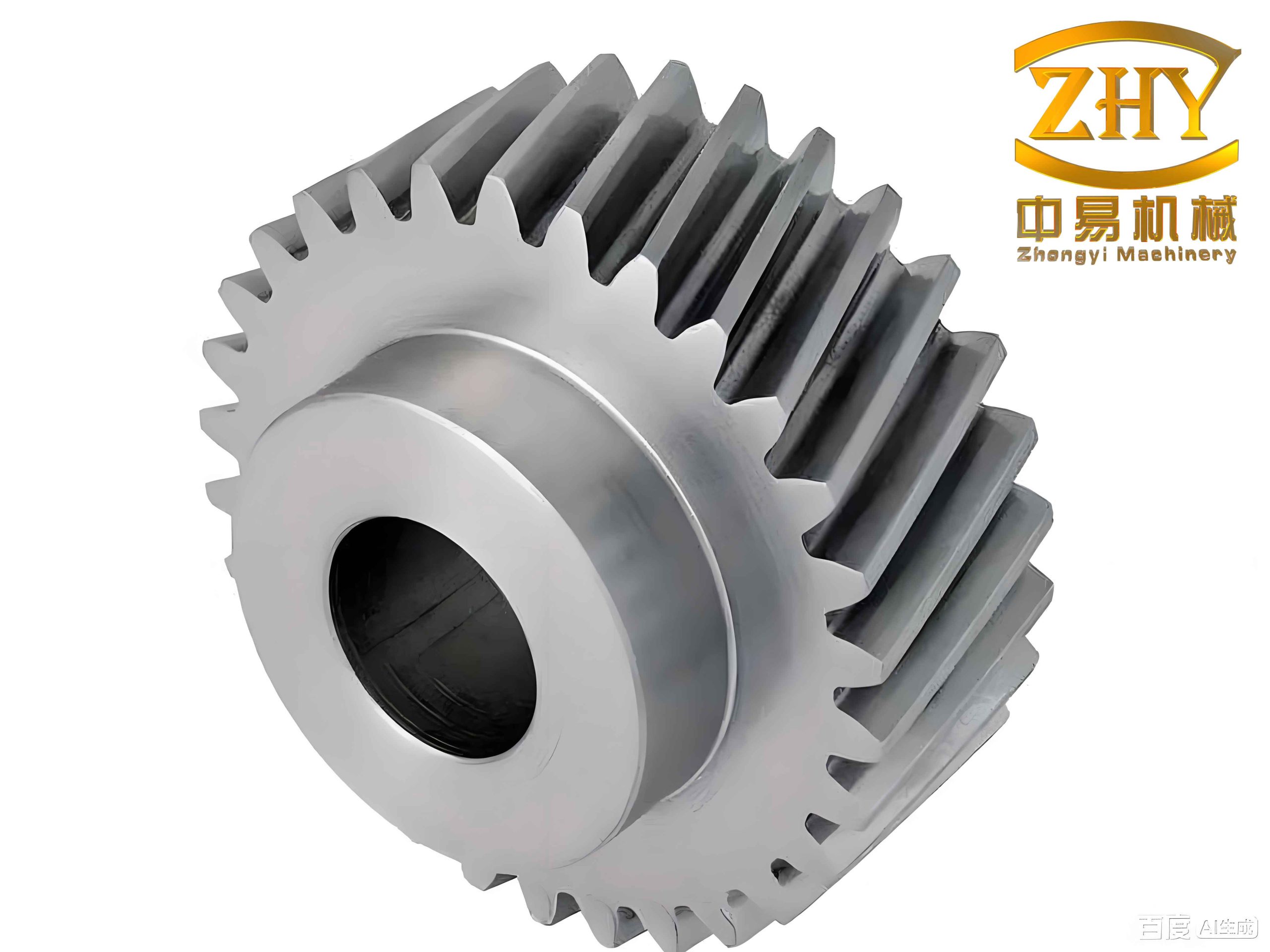
I focus on a helical gear pair and propose an analytical calculation method for multi-tooth impact based on energy conservation. I then calculate the tooth surface contact temperature, derive a calculation method for impact excitation that considers temperature, and analyze the influence of impact on the meshing state of the helical gear pair. Finally, I develop a software program for calculating the impact excitation of high-speed and heavy-load involute helical gear pairs. The main contents and conclusions are summarized as follows.
Determination of the Meshing-In Impact Point for Helical Gear Pairs
In an ideal meshing state, the base pitch of the driving and driven helical gears is identical, so no velocity difference occurs along the line of action, and no meshing-in impact is generated. In actual operation, however, the gear load causes elastic deformation, changing the base pitch. As a result, the tip of the driven gear contacts the driving gear surface outside the theoretical line of action, producing a normal impact velocity and a line-of-action external meshing-in impact. I use the inversion method to determine the position of the meshing-in impact point. The distance from the center of the driving gear to the impact point can be expressed as
$$r_{O_1D} = \sqrt{r_{a2}^2 + a^2 – 2 r_{a2} a \cos(\theta_2 + \gamma_2)}$$
where \(r_{a2}\) is the addendum circle radius of the driven gear, \(a\) is the center distance, \(\theta_2\) is the inversion angle of the driven gear, and \(\gamma_2 = \alpha_{a2} – \alpha_0\), with \(\alpha_{a2}\) being the addendum pressure angle and \(\alpha_0\) the pitch circle pressure angle. The inversion angle of the driving gear is \(\theta_1 = \theta_2 / k\), where \(k\) is the transmission ratio. The angle \(\theta_1\) can also be written as
$$\theta_1 = \arccos\left(\frac{r_{a2}^2 + a^2 – r_{O_1D}^2}{2 r_{a2} a}\right) – \varepsilon_1 – \gamma_2$$
where \(\varepsilon_1\) is the involute angle at the impact point. The involute angle is given by
$$\varepsilon_1 = \mathrm{inv}\,\alpha_{D1} – \mathrm{inv}\,\alpha_{E1}$$
with \(\alpha_{D1} = \arccos(r_{b1} / r_{O_1D})\), \(r_{b1}\) being the base circle radius of the driving gear. The total deformation along the line of action due to load is
$$\delta_{\Sigma} = \delta_1 + \delta_2 + \delta_c$$
where \(\delta_1\) and \(\delta_2\) are the flexural deformations of the driving and driven gears, and \(\delta_c\) is the contact deformation. The equivalent deformation angle caused by gear deformation is
$$\varphi = \frac{\delta_{\Sigma}}{r_{b2}}$$
Solving the above equations yields the meshing-in impact point \(D\) and the impact radius \(r_{O_1D}\). This radius is essential for calculating the impact velocity and the resulting impact force in the helical gear pair.
Line-of-Action External Meshing-In Impact Force
For a helical gear, the meshing-in impact occurs only on the side that first enters meshing. The length of the impact contact line strongly affects the magnitude of the impact force. I use the slice method to divide the helical gear into a finite number of independent spur gear slices. The impact contact line length for tooth pair I is
$$L_1 = \frac{L_{ED’}}{\sin\beta_b}$$
where \(L_{ED’}\) is the projected length on the theoretical contact line and \(\beta_b\) is the base helix angle. Each slice has a width \(\Delta x = L_3 \cos\beta_b / N\), with \(N\) being the number of slices. The impact radius for each slice is
$$r_{D_i} = \sqrt{(L_{N_1E} + L_{ED_i})^2 + r_{b1}^2}$$
The meshing-in impact velocity for each slice is
$$\Delta v_{n_i} = v_{n1_i} – v_{n2_i} = \omega_1 r_{b1} – \omega_2 r’_{b2_i}$$
where \(\omega_1\) and \(\omega_2\) are the angular velocities of the driving and driven gears, and \(r’_{b2_i}\) is the instantaneous base circle radius of the driven gear. The equivalent mass on the line of action for each slice is
$$m_{red1_i} = \frac{J_{1_i}}{r_{b1}^2} = \frac{\pi \rho}{2} (r_{b1}^2 – r_{h1}^2) \Delta x$$
$$m_{red2_i} = \frac{J_{2_i}}{r’_{b2_i}^2} = \frac{\pi \rho}{2} (r’_{b2_i}^2 – r_{h2}^2) \Delta x$$
where \(J_{1_i}\) and \(J_{2_i}\) are the moments of inertia, \(r_{h1}\) and \(r_{h2}\) are the hub radii, and \(\rho\) is the density. According to impact mechanics, the maximum impact force \(F_{s_i}\), maximum deformation \(\delta_{s_i}\), and impact energy \(E_{k_i}\) for each slice are related by
$$E_{k_i} = \frac{1}{2} \frac{m_{red1_i} m_{red2_i}}{m_{red1_i} + m_{red2_i}} \Delta v_{n_i}^2 = \frac{1}{2} F_{s_i} \delta_{s_i}, \quad F_{s_i} = \frac{\delta_{s_i}}{q_{s_i} \Delta x}$$
where \(q_{s_i}\) is the comprehensive compliance. Solving these equations gives the maximum impact force per slice:
$$F_{s_i} = \Delta v_{n_i} \sqrt{\frac{\Delta x J_{1_i} J_{2_i}}{(J_{1_i} r’_{b2_i}^2 + J_{2_i} r_{b1}^2) q_{s_i}}}$$
The maximum meshing-in impact force of tooth pair I is obtained by integrating along the contact line:
$$F_{sm1} = \int_{0}^{L_1} F_{s_i} \, dx$$
Assuming the impact force follows a sinusoidal pulse, the impact force of tooth pair I can be written as
$$F_{s1}(t) = F_{sm1} \sin\left(\frac{\pi t}{t_{s1}}\right) = F_{sm1} \sin(\omega_{s1} t)$$
where \(\omega_{s1} = \pi / t_{s1}\). The impact time \(t_{s1}\) is determined by the impulse theorem:
$$\int_{0}^{t_{s1}} F_{s1}(t) \, dt = m_{red} \Delta v_n$$
and thus
$$t_{s1} = \frac{\pi m_{red} \Delta v_n}{2 F_{sm1}}$$
This analytical approach allows me to calculate the line-of-action external meshing-in impact force for a helical gear pair with high efficiency and reasonable accuracy.
Multi-Tooth Impact Induced by Meshing-In Impact
Because the meshing-in impact occurs on one side of the helical gear pair, the contact force on that side changes abruptly, causing slight fluctuations in the speeds of the driving and driven gears. This speed difference induces internal impact on tooth pairs II and III along the line of action, thereby intensifying gear vibration. I establish a multi-tooth impact model based on energy conservation to quantify these effects.
The impact kinetic energy generated by the normal impact velocity is
$$E_k = \frac{1}{2} \sum_{i=1}^{N} \frac{J_{1_i} J_{2_i}}{J_{1_i} r’_{b2_i}^2 + J_{2_i} r_{b1}^2} \Delta v_{n_i}^2$$
The tangential impact velocity produces a tangential impulse energy \(W_f\), which is assumed to be dissipated by friction work:
$$W_f = \frac{1}{2} \sum_{i=1}^{N} \frac{J_{1_i} J_{2_i}}{J_{1_i} r’_{b2_i}^2 + J_{2_i} r_{b1}^2} \Delta v_{\tau_i}^2$$
where \(\Delta v_{\tau_i} = \omega_1 r_{b1} \tan\alpha_{D1_i} – \omega_2 r’_{b2_i} \tan\alpha_{D2_i}\). The velocities of the driving and driven gears after impact are denoted \(v’_1\) and \(v’_2\). By considering the slice method, the velocity of each slice along the line of action can be expressed as
$$v’_1(j) = v_1 + (v’_1 – v_1) \frac{j-1}{M-1}, \quad j = 1, 2, \ldots, M$$
$$v’_2(j) = v_2 + (v’_2 – v_2) \frac{j-1}{M-1}, \quad j = 1, 2, \ldots, M$$
From energy conservation,
$$\frac{1}{2} m_{red1} v_1^2 = \frac{1}{2} m_{red1} v_1’^2 + E_k + W_f$$
$$\frac{1}{2} m_{red2} v_2^2 + E_k = \frac{1}{2} m_{red2} v_2’^2$$
The maximum tooth surface gap generated by the meshing-in impact is
$$L_{\max} = \frac{(v’_1 + v_1)t_{s1}}{2} – \frac{(v’_2 + v_2)t_{s1}}{2}$$
Assuming the gap varies linearly along the tooth width, the gap for each slice is
$$L_{1j} = L_{\max} \left(1 – \frac{j-1}{M-1}\right)$$
The impact contact line lengths for tooth pairs II and III are
$$L_2 = \frac{p_{bt} – \theta_1 r_{b1}}{\sin\beta_b}$$
$$L_3 = \frac{b – p_{bt} + L_{EF} – \theta_1 r_{b1}}{\cos\beta_b \sin\beta_b}$$
where \(p_{bt}\) is the transverse pitch, \(b\) is the tooth width, and \(L_{EF}\) is the actual line of action length. The re-meshing velocities of the driving and driven gears are
$$v’_{1j} = v_{1j} + a_1 t_j, \quad v’_{2j} = v_{2j} – a_2 t_j$$
with \(a_1 = F_t / m_{red1}\), \(a_2 = F_t / m_{red2}\), and the meshing time \(t_j\) given by
$$t_j = \frac{(v’_{2j} – v’_{1j}) + \sqrt{2(v’_{2j} – v’_{1j})L_{1j} + (a_1 + a_2)L_{1j}^2}}{a_1 + a_2}$$
The impact velocity for each slice of tooth pair II is
$$\Delta v_{s_j} = v’_{1j} – v’_{2j}$$
The maximum impact force per slice for tooth pair II is
$$F_{s_j} = \Delta v_{s_j} \sqrt{\frac{\Delta y J_{1_j} J_{2_j}}{(J_{1_j} r_{b2}^2 + J_{2_j} r_{b1}^2) q_{s_j}}}$$
Integrating along the tooth width gives the maximum impact force of tooth pair II:
$$F_{sm2} = \int_{0}^{L_2} F_{s_j} \, dy$$
Similarly, the impact force of tooth pair III is obtained as \(F_{s3}\). The total multi-tooth impact force of the helical gear pair is
$$F_{sm} = F_{s1} + F_{s2} + F_{s3}$$
Using a representative involute helical gear pair, I calculate the multi-tooth impact excitation. The gear parameters and operating conditions are listed in Table 1.
| Parameter | Driving gear | Driven gear |
|---|---|---|
| Number of teeth, \(Z\) | 41 | 161 |
| Normal module, \(m_n\) (mm) | 12 | 12 |
| Pressure angle, \(\alpha_n\) (°) | 20 | 20 |
| Helix angle, \(\beta\) (°) | 12 | -12 |
| Tooth width, \(b\) (mm) | 185 | 180 |
| Center distance, \(a\) (mm) | 1250 | 1250 |
| Addendum coefficient, \(h_{an}\) | 1 | 1 |
| Clearance coefficient, \(c_n\) | 0.4 | 0.4 |
| Input speed, \(n\) (r·min⁻¹) | 3000 | — |
| Input power, \(P\) (kW) | 2720 | — |
The calculated impact excitation results show that the maximum line-of-action external meshing-in impact force of tooth pair I is 7114.3 N, the maximum internal impact force of tooth pair II is 3092.2 N, and the maximum internal impact force of tooth pair III is 1406.1 N. Because tooth pair I undergoes meshing-in impact, its impact excitation is the largest. Tooth pairs II and III are induced by the meshing-in impact of tooth pair I; their impact contact line lengths directly determine the impact force. Since tooth pair III is about to exit meshing, its contact line is shorter than that of tooth pair II, so its impact force is the smallest.
Influence of Gear Parameters on Impact Excitation
I analyze the influence of input speed, input torque, and gear module on the impact excitation of the helical gear pair. The results are summarized in Table 2.
| Parameter | Trend of tooth pair I impact | Trend of tooth pair II and III impact |
|---|---|---|
| Input speed increases | Increases | Increases |
| Input torque increases | Increases | Increases |
| Gear module increases | Increases | Decreases |
As the input speed increases, the angular velocity of the helical gear pair increases, leading to a larger impact velocity and intensified meshing-in impact. A higher input torque increases the normal load per unit tooth width, enlarging the loaded deformation and aggravating the line-of-action external impact. When the gear module increases, the impact radius during meshing-in becomes larger, which increases the impact velocity and intensifies the meshing-in impact of the helical gear. However, the increased gear mass reduces the speed fluctuation caused by the meshing-in impact, thereby decreasing the impact forces of tooth pairs II and III.
Temperature Effect on Impact Excitation
Under high-speed and heavy-load conditions, the relative sliding velocity on the tooth surface is high, and friction converts a large amount of energy into heat. This raises the tooth surface temperature and causes thermal deformation of the tooth profile, which changes the profile error and intensifies the impact of the helical gear pair. I therefore calculate the tooth surface contact temperature using the Blok flash temperature theory.
The flash temperature \(T_f\) is given by
$$T_f = \frac{\zeta \mu(t) F_e |v_1(t) – v_2(t)|}{\sqrt{g_1 \rho_1 c_1 v_1(t)} + \sqrt{g_2 \rho_2 c_2 v_2(t)} \cdot B(t)}$$
where \(\zeta\) is the flash temperature coefficient, \(\mu(t)\) is the time-varying friction coefficient, \(F_e\) is the load per unit tooth width, \(v_1(t)\) and \(v_2(t)\) are the tangential velocities, \(g_1, g_2\) are the thermal conductivities, \(\rho_1, \rho_2\) are the densities, \(c_1, c_2\) are the specific heats, and \(B(t)\) is the half-width of the contact band. The contact half-width is calculated from Hertzian contact theory:
$$B(t) = \kappa \sqrt{\frac{2(1-\nu^2)F_n R(t)}{E b}}$$
where \(\kappa = 1.128\), \(\nu\) is Poisson’s ratio, \(F_n\) is the normal load, \(E\) is the elastic modulus, and \(R(t)\) is the comprehensive curvature radius. The relative sliding velocity is
$$v(t) = v_1(t) – v_2(t)$$
I use the Doolittle-Tait free volume viscosity model to capture the viscosity-temperature effect of the lubricating oil:
$$\eta(T) = \eta_0 \exp\left\{ \frac{B_0 R_0}{V_0} \left[ \frac{1}{1 – \varepsilon(T – T_0)} – \frac{1}{1 – \varepsilon(T_0 – T_r)} \right] \right\}$$
where the parameters are defined in the usual way. The thermal deformation of the tooth profile caused by the flash temperature is
$$\delta_T = \frac{2(T_f \lambda r_b + u_b – S \lambda r_b)}{\cos\alpha_k} – \frac{r_b + u_b}{\cos\alpha_k} \left[ \mathrm{inv}\,\alpha_k – \mathrm{inv}\,\alpha \right]$$
where \(\lambda\) is the linear expansion coefficient, \(r_b\) is the base circle radius, \(u_b\) is the thermal deformation of the base circle, \(S\) is the tooth thickness on the pitch circle, and \(\alpha_k\) is the pressure angle after thermal deformation. The total deformation along the line of action considering temperature becomes
$$\delta’_{\Sigma} = \delta_1 + \delta_2 + \delta_c + \delta_T$$
The equivalent deformation angle is updated as
$$\varphi’ = \frac{\delta’_{\Sigma}}{r_{b2} + u_{b2}}$$
Using the new deformation angle, I recalculate the meshing-in impact radius and the impact velocity, and then obtain the temperature-considered impact excitation of the helical gear pair. The results are compared in Table 3.
| Quantity | Without temperature | With temperature | Increase |
|---|---|---|---|
| Maximum meshing-in impact force of tooth pair I (N) | 7114.3 | 8264.7 | 13.93% |
| Maximum impact force of tooth pair II (N) | 3092.2 | 3460.9 | 10.65% |
| Maximum impact force of tooth pair III (N) | 1406.1 | 1573.5 | 10.64% |
The results show that tooth surface temperature significantly intensifies the impact excitation of the helical gear pair. The effect is more pronounced for the meshing-in impact of tooth pair I and relatively smaller for tooth pairs II and III.
Influence of Impact on Meshing State
Under high-speed and heavy-load conditions, the intensified impact excitation of the helical gear pair affects the meshing state, including the tooth surface friction and the dynamic contact force. I investigate these effects in detail.
Time-Varying Contact Line Length
The contact line length of a single tooth in a helical gear pair changes from zero to a maximum and then back to zero. The maximum contact line length depends on the transverse contact ratio \(\varepsilon_\alpha\) and the axial contact ratio \(\varepsilon_\beta\). When \(\varepsilon_\alpha \ge \varepsilon_\beta\), the single-tooth time-varying contact line length \(L(t)\) can be expressed as
$$L(t) = \begin{cases}
L_{\max} t_{\beta c} / t, & t \in [0, t_{\beta c}] \\
L_{\max}, & t \in [t_{\beta c}, t_{\alpha c}] \\
L_{\max} (t_{\gamma c} – t) / (t_{\gamma c} – t_{\alpha c}), & t \in [t_{\alpha c}, t_{\gamma c}]
\end{cases}$$
When \(\varepsilon_\alpha < \varepsilon_\beta\), the contact line length is
$$L(t) = \begin{cases}
L_{\max} t_{\alpha c} / t, & t \in [0, t_{\alpha c}] \\
L_{\max}, & t \in [t_{\alpha c}, t_{\beta c}] \\
L_{\max} (t_{\gamma c} – t) / (t_{\gamma c} – t_{\beta c}), & t \in [t_{\beta c}, t_{\gamma c}]
\end{cases}$$
The comprehensive contact line length is the sum of the contact line lengths of all meshing tooth pairs:
$$L(t) = \sum_{i=1}^{M} L_i(t)$$
Because the total contact ratio of a helical gear pair is not an integer, the meshing process exhibits alternating two-tooth and three-tooth contact. Therefore, the comprehensive contact line length is time-varying and periodic.
Time-Varying Friction Coefficient Considering Impact
I divide the complete meshing interval of the helical gear pair into three friction states: impact friction, mixed lubrication, and elastohydrodynamic lubrication. Impact friction occurs during the line-of-action external meshing-in impact, where the oil film is broken and the tooth surfaces are in direct contact. The average impact friction coefficient is
$$\mu_I = \frac{\int_{0}^{T_s} F_{\tau} \, dt}{\int_{0}^{T_s} F_n \, dt} = \frac{\Delta v_{D2\tau}}{\Delta v_{D2n}}$$
where \(\Delta v_{D2\tau}\) and \(\Delta v_{D2n}\) are the tangential and normal impact velocities. The tangential and normal impact velocities are
$$\Delta v_{D2\tau} = v_2 \sin\beta – v’_2 \sin\beta’, \quad \Delta v_{D2n} = v_2 \cos\beta – v’_2 \cos\beta’$$
For elastohydrodynamic lubrication, I use the time-varying friction coefficient model:
$$\mu_{EL}(t) = e^{f(SR, P_{\max}, \eta_0, S)} P_{\max}^{b_1} SR(t)^{b_2} v_e(t)^{b_3} \eta_0^{b_4} R(t)^{b_5}$$
where the function \(f\) is
$$f = b_1 + b_4 \log_{10} P_{\max} + b_5 \log_{10} \eta_0 + b_6 e^{SR(t)} + b_7 \log_{10} SR(t) + b_8 \log_{10} P_{\max} \log_{10} \eta_0 + b_9 \log_{10} P_{\max} \log_{10} SR(t)$$
The mixed lubrication friction coefficient is a weighted sum of the impact friction and elastohydrodynamic friction coefficients:
$$\mu_{ML} = \lambda f \mu_{EL} + (1 – \lambda f) \mu_I$$
where
$$\lambda f = 1.21 \lambda^{0.64} (1 + 0.37 \lambda^{1.26})$$
and \(\lambda = h_{\min} / R_a\), with \(h_{\min}\) being the minimum oil film thickness:
$$h_{\min} = 2.69 R U^{0.67} G^{0.53} W^{-0.67}$$
The time-varying friction coefficient of the helical gear pair is obtained by combining these three states. The results show that the impact friction coefficient is high at the beginning of meshing, then decreases as the oil film recovers, and finally approaches the elastohydrodynamic lubrication value.
Friction Excitation Force
Using the slice method, I divide the helical gear pair into finite independent spur gear slices. The friction coefficient of the \(j\)-th slice is
$$\mu_j(t) = \mu_0(t) \eta_j(t)$$
where \(\eta_j(t)\) is a sign function determined by the relative sliding velocity direction. The friction force of the \(j\)-th slice is
$$F_{f1_j}(t) = F_{f2_j}(t) = \frac{F_n \mu_j(t) \Delta x}{L(t) \cos\beta}$$
The total friction excitation force is
$$F_{f1}(t) = \sum_{j=1}^{m} F_{f1_j}(t)$$
The friction torques acting on the driving and driven gears are
$$T_{f1}(t) = \sum_{j=1}^{m} F_{f1_j}(t) L_{1_j}(t), \quad T_{f2}(t) = \sum_{j=1}^{m} F_{f2_j}(t) L_{2_j}(t)$$
I calculate the friction excitation force of the helical gear pair with and without impact. The results are compared in Table 4.
| Condition | Mean friction force (N) | Maximum single-tooth friction force (N) |
|---|---|---|
| Without meshing-in impact | 7.7 | -1563.5 |
| With meshing-in impact | -206.1 | -1778.4 |
When the helical gear pair does not experience meshing-in impact, the friction force on the upper side of the pitch line is slightly larger than that on the lower side, and the two sides largely cancel each other, resulting in a small friction excitation force. When meshing-in impact occurs, the friction force on the lower side of the pitch line increases, causing an imbalance between the two sides. The friction force of the helical gear pair increases and the friction direction changes, which affects the smoothness of gear transmission.
Dynamic Contact Force Considering Impact
I establish an 8-degree-of-freedom lumped-mass dynamic model of the helical gear transmission system, including bending, torsion, and axial motions. The generalized displacement vector is
$$\mathbf{q} = \{x_1, y_1, z_1, \theta_1, x_2, y_2, z_2, \theta_2\}^T$$
The relative displacement along the normal direction at the meshing point is
$$\delta_n = (x_1 – x_2)\sin\alpha + (y_1 – y_2)\cos\alpha + (r_1\theta_1 – r_2\theta_2)\cos\beta + (z_1 – z_2)\sin\beta – e(t)$$
The dynamic meshing force is
$$F_n = k_m(t) \delta_n + c_m \dot{\delta}_n$$
and the components along the coordinate axes are
$$F_x = F_n \sin\alpha, \quad F_y = F_n \cos\alpha \cos\beta, \quad F_z = F_n \cos\alpha \sin\beta$$
The vibration differential equations of the helical gear transmission system are
$$m_1 \ddot{x}_1 + c_{1x} \dot{x}_1 + k_{1x} x_1 = F_x$$
$$m_1 \ddot{y}_1 + c_{1y} \dot{y}_1 + k_{1y} y_1 = F_y$$
$$m_1 \ddot{z}_1 + c_{1z} \dot{z}_1 + k_{1z} z_1 = F_z$$
$$I_1 \ddot{\theta}_1 = T_1 – F_y r_{b1} – F_s r_{b1}$$
$$m_2 \ddot{x}_2 + c_{2x} \dot{x}_2 + k_{2x} x_2 = -F_x$$
$$m_2 \ddot{y}_2 + c_{2y} \dot{y}_2 + k_{2y} y_2 = -F_y$$
$$m_2 \ddot{z}_2 + c_{2z} \dot{z}_2 + k_{2z} z_2 = -F_z$$
$$I_2 \ddot{\theta}_2 = T_2 + F_y r_{b2} + F_s r_{b2}$$
I solve these equations using the fourth-order Runge-Kutta method with variable step size. The dynamic contact force is then calculated as
$$F_m = k_m(t) \delta_n + c_m \dot{\delta}_n + F_s$$
The results are summarized in Table 5.
| Condition | Mean contact force (N) | Amplitude (N) |
|---|---|---|
| Without gear impact | 40075 | 38071 |
| With gear impact | 40180 | 36751 |
The mean contact force increases by 0.26%, while the amplitude decreases by 3.47%. The gear impact increases the contact force amplitude at the second, third, and fourth harmonics of the meshing frequency, but decreases the amplitude at the meshing frequency itself.
Software Development
Based on the theoretical research above, I develop a software program for calculating the impact excitation of high-speed and heavy-load involute helical gear pairs using MATLAB. The software includes a main interface, a parameter input interface, and a result display interface. The parameter input interface allows the user to enter gear parameters, operating conditions, material properties, and temperature parameters. The result display interface presents the multi-tooth impact excitation, tooth surface friction, and tooth surface contact force. The software is designed with a user-friendly graphical interface, and the calculation results are consistent with the analytical results. It improves the design efficiency of high-speed and heavy-load helical gear transmission systems.
Conclusions
I have investigated the impact excitation mechanism of high-speed and heavy-load involute helical gear pairs. The main conclusions are as follows.
First, I established an analytical model for the meshing-in impact of a helical gear pair and calculated the line-of-action external meshing-in impact force. Based on energy conservation, I determined the internal impact velocities of tooth pairs II and III induced by the meshing-in impact. The maximum meshing-in impact force of tooth pair I is 7114.3 N, the maximum impact force of tooth pair II is 3092.2 N, and the maximum impact force of tooth pair III is 1406.1 N. The impact excitation of the helical gear increases with increasing input torque and input speed. The meshing-in impact increases with increasing gear module, while the impact forces of tooth pairs II and III decrease with increasing gear module.
Second, I calculated the tooth surface contact temperature using the Blok flash temperature theory and obtained the thermal deformation of the tooth profile. Considering the thermal deformation, the maximum meshing-in impact force increases to 8264.7 N, an increase of 13.93%. The maximum impact force of tooth pair II increases to 3460.9 N, an increase of 10.65%, and that of tooth pair III increases to 1573.5 N, an increase of 10.64%. The results indicate that the tooth surface temperature significantly intensifies the impact excitation of the helical gear pair, with a larger effect on the meshing-in impact and a smaller effect on tooth pairs II and III.
Third, I calculated the time-varying contact line length and the time-varying friction coefficient considering impact. The friction excitation force of the helical gear pair was obtained. Without meshing-in impact, the mean friction force is 7.7 N; with meshing-in impact, the mean friction force is -206.1 N. The imbalance between the friction forces on the two sides of the pitch line increases, and the friction direction changes, which affects the transmission smoothness. I also established a dynamic model of the helical gear transmission system and obtained the dynamic contact force. The gear impact increases the mean contact force by 0.26% and decreases the amplitude by 3.47%. It increases the contact force amplitude at the second, third, and fourth harmonics of the meshing frequency and decreases the amplitude at the meshing frequency.
Fourth, I developed a software program for calculating the impact excitation of high-speed and heavy-load involute helical gear pairs. The software provides an integrated visual design and improves the design efficiency of helical gear transmission systems.
Future work should consider more factors such as system equivalent errors and comprehensive tooth deformation, the influence of gear impact on the temperature field of the helical gear transmission system, and a more comprehensive study of the impact of gear excitation on the meshing state.