
In this study, I investigated the surface quenching process of helical gears using a high-frequency moving induction heating method. Helical gears are widely used in engineering machinery and aerospace transmission systems because they provide larger contact area, smoother meshing, and lower axial force compared with spur gears. However, the quality and accuracy of helical gears directly affect the performance, reliability, and service life of the entire mechanical system. Traditional quenching technologies often produce non-uniform surface temperature distributions, excessive quenching stresses, cracks, and distortion, which reduce the precision and durability of helical gears. To overcome these limitations, I developed a cyclic scanning moving induction heating strategy combined with a profiled induction coil. The method was designed to achieve uniform heating and hardening along the complex tooth profile of helical gears, thereby improving surface hardness, wear resistance, and dimensional stability.
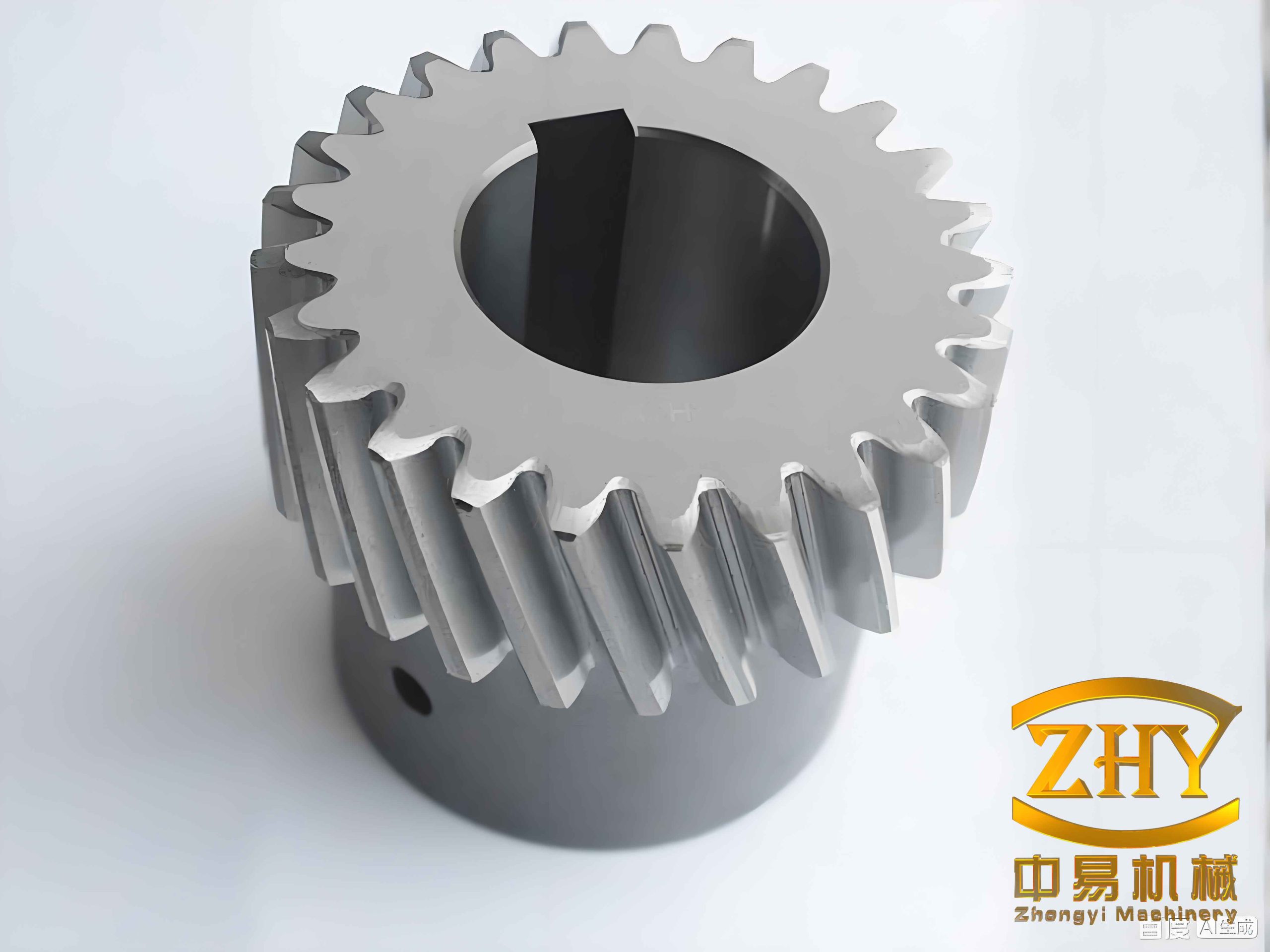
The research combined theoretical analysis, multi-physics numerical simulation, parametric investigation, and experimental validation. I established a three-dimensional coupled electromagnetic–thermal–motion–stress–microstructure model for helical gears. A cyclic scanning moving heating approach was proposed, in which the helical gear performs a variable-speed helical motion relative to a profiled induction coil. This motion was realized by coordinating the axial linear velocity and the rotational angular velocity of the helical gear. The resulting temperature field, magnetic field, stress field, austenite transformation, martensite transformation, residual stress, and hardness distribution were systematically analyzed. I also examined the effects of motion parameters, current density, current frequency, and cooling medium on the quenching quality. Finally, I conducted induction quenching experiments on helical gears, including temperature measurement, metallographic observation, and microhardness testing, to verify the feasibility and accuracy of the proposed method.
Theoretical Fundamentals of Moving Induction Quenching for Helical Gears
Induction heating of helical gears is based on electromagnetic induction and the Joule–Lenz effect. When an alternating current flows through an induction coil, an alternating magnetic field is generated. This magnetic field induces an electromotive force in the surface region of the helical gear. Because the surface forms a closed conductive path, eddy currents are generated. These eddy currents produce Joule heat, which raises the temperature of the helical gear surface. The heat generated in the surface layer is the primary internal heat source during induction heating, while heat conduction, convection, and radiation also influence the temperature evolution.
The electromagnetic field in the induction heating process can be described by Maxwell’s equations. The differential form is given by:
$$
\nabla \times \mathbf{H} = \mathbf{J} + \frac{\partial \mathbf{D}}{\partial t}
$$
$$
\nabla \times \mathbf{E} = -\frac{\partial \mathbf{B}}{\partial t}
$$
$$
\nabla \cdot \mathbf{D} = 0
$$
$$
\nabla \cdot \mathbf{B} = 0
$$
where \(\mathbf{H}\) is the magnetic field intensity, \(\mathbf{J}\) is the current density, \(\mathbf{D}\) is the electric displacement, \(\mathbf{E}\) is the electric field intensity, and \(\mathbf{B}\) is the magnetic flux density. The constitutive relations are:
$$
\mathbf{D} = \varepsilon \mathbf{E}
$$
$$
\mathbf{J} = \sigma \mathbf{E}
$$
$$
\mathbf{B} = \mu \mathbf{H}
$$
where \(\varepsilon\) is the permittivity, \(\sigma\) is the electrical conductivity, and \(\mu\) is the magnetic permeability. By introducing the magnetic vector potential \(\mathbf{A}\) and the electric scalar potential \(\phi\), the magnetic flux density and electric field can be expressed as:
$$
\mathbf{B} = \nabla \times \mathbf{A}
$$
$$
\mathbf{E} = -\frac{\partial \mathbf{A}}{\partial t} – \nabla \phi
$$
The current density then becomes:
$$
\mathbf{J} = -\sigma \frac{\partial \mathbf{A}}{\partial t} – \sigma \nabla \phi
$$
The eddy current distribution in helical gears is strongly affected by the skin effect. The current density decays exponentially from the surface toward the interior:
$$
I_x = I_0 e^{-x/\delta}
$$
where \(I_x\) is the current density at distance \(x\) from the surface, \(I_0\) is the surface current density, and \(\delta\) is the current penetration depth. The penetration depth is given by:
$$
\delta = \sqrt{\frac{\rho}{\pi f \mu}}
$$
where \(\rho\) is the electrical resistivity, \(f\) is the current frequency, and \(\mu\) is the magnetic permeability. For helical gears, the skin effect concentrates the induced current in a thin surface layer, which is beneficial for surface hardening but can also cause overheating at edges and corners. Therefore, the coil geometry and process parameters must be carefully designed.
The heat generated by eddy currents is described by the Joule–Lenz law:
$$
q_v = \rho J^2
$$
where \(q_v\) is the volumetric heat source intensity. The transient temperature field in helical gears during induction heating is governed by the three-dimensional heat conduction equation with an internal heat source:
$$
\rho c \frac{\partial T}{\partial t} = \frac{\partial}{\partial x}\left(k \frac{\partial T}{\partial x}\right) + \frac{\partial}{\partial y}\left(k \frac{\partial T}{\partial y}\right) + \frac{\partial}{\partial z}\left(k \frac{\partial T}{\partial z}\right) + q_v
$$
where \(T\) is temperature, \(\rho\) is density, \(c\) is specific heat capacity, and \(k\) is thermal conductivity. The boundary conditions include specified temperature, specified heat flux, convection, and radiation. Convection is particularly important during quenching, where the cooling medium removes heat from the helical gear surface. The convective heat flux is described by Newton’s law of cooling:
$$
q = h(T_s – T_\infty)
$$
where \(h\) is the convective heat transfer coefficient, \(T_s\) is the surface temperature, and \(T_\infty\) is the ambient or coolant temperature. Radiation heat transfer is given by the Stefan–Boltzmann law:
$$
q = \varepsilon \sigma (T_s^4 – T_\infty^4)
$$
During heating and cooling, helical gears undergo austenite and martensite transformations. The diffusion-controlled transformation from pearlite to austenite can be described by the Avrami equation:
$$
\xi_{CP} = 1 – \exp\left[-b(T) t^{n(T)}\right]
$$
where \(\xi_{CP}\) is the volume fraction of the transformed phase, \(b(T)\) and \(n(T)\) are temperature-dependent coefficients. For continuous heating, the differential form is often used:
$$
\frac{d\xi_{CP}}{dt} = \left[\frac{\ln(1-\xi_{CP})}{b(T)}\right]^{1/n(T)} \cdot n(T) b(T) (1-\xi_{CP})
$$
The austenitization kinetics can also be expressed using the Johnson–Mehl–Avrami–Kolmogorov equation:
$$
\xi = 1 – \exp\left[-D_0 \exp\left(-\frac{Q}{RT_{abs}}\right) t^n\right]
$$
where \(D_0\) is a pre-exponential factor, \(Q\) is the activation energy, \(R\) is the gas constant, and \(T_{abs}\) is the absolute temperature. The martensitic transformation is a non-diffusion transformation and can be described by the Koistinen–Marburger equation:
$$
\xi_m = \xi_a \left[1 – \exp\left(-\alpha (M_s – T)\right)\right]
$$
where \(\xi_m\) is the martensite volume fraction, \(\xi_a\) is the austenite volume fraction, \(M_s\) is the martensite start temperature, and \(\alpha\) is a constant typically around \(1.10 \times 10^{-2}\). The total strain during induction quenching includes thermal strain, elastic strain, plastic strain, transformation strain, and transformation-induced plastic strain:
$$
\{\varepsilon\} = \{\varepsilon_{th}\} + \{\varepsilon_e\} + \{\varepsilon_p\} + \{\varepsilon_{tr}\} + \{\varepsilon_{tp}\}
$$
The thermal strain is calculated as:
$$
d\varepsilon_{th} = \sum_{i=1}^{n} \xi_i \alpha_i dT
$$
where \(\xi_i\) is the volume fraction of phase \(i\) and \(\alpha_i\) is its thermal expansion coefficient. The transformation strain is given by:
$$
d\varepsilon_{tr} = \sum_{i=1}^{n} \beta_i d\xi_i
$$
where \(\beta_i\) is the volume change associated with phase \(i\). The transformation-induced plastic strain can be modeled as:
$$
d\varepsilon_{tp} = \frac{3}{2} D (1-\xi) d\xi \cdot \mathbf{s}
$$
where \(D\) is the transformation parameter and \(\mathbf{s}\) is the deviatoric stress tensor.
Numerical Model and Cyclic Scanning Strategy for Helical Gears
I established a three-dimensional finite element model for the moving induction quenching of helical gears using a commercial DEFORM environment. The helical gear had a module of 6 mm, 12 teeth, a face width of 40 mm, and a helix angle of \(10^\circ\). The profiled induction coil was designed with a hollow rectangular cross-section and a local profiling width of 10 mm. To reduce the sharp corner effect at the tooth tip, the distance between the coil and the tooth tip was increased to 5.5 mm, while the distance to the tooth root was 2 mm. The coil cross-sectional area was \(3252.5\ \text{mm}^2\). The material of the helical gears was 45 steel, and its chemical composition is given in Table 1. The temperature-dependent thermal physical properties, including thermal conductivity, specific heat capacity, electrical resistivity, and relative magnetic permeability, were imported into the simulation.
| Element | C | Si | Mn | Cr | Ni | Cu |
|---|---|---|---|---|---|---|
| Mass fraction (%) | 0.42–0.50 | 0.17–0.37 | 0.50–0.80 | ≤0.25 | ≤0.30 | ≤0.25 |
The numerical simulation was divided into two stages: induction heating and surface quenching. During induction heating, the electromagnetic, thermal, motion, stress, and microstructure fields were coupled. The helical gear performed a variable-speed helical motion relative to the fixed profiled induction coil. This motion was achieved by coordinating the axial linear velocity \(v_t\) and the rotational angular velocity \(\omega_t\). To maintain a constant gap between the helical gear surface and the coil, the following relationship was satisfied:
$$
v_t = r \omega_t \tan \beta
$$
where \(r\) is the pitch circle radius of the helical gear and \(\beta\) is the helix angle. By adjusting \(v_t\) and \(\omega_t\) simultaneously, the helical gear moves along a helical path, ensuring that the tooth profile remains at a constant distance from the profiled coil. The cyclic scanning strategy was implemented by repeatedly moving the helical gear forward and backward through the coil. The motion parameters used in the baseline simulation are listed in Table 2.
| Motion stage | Axial linear velocity \(v\) (mm/s) | Rotational angular velocity \(\omega\) (rad/s) |
|---|---|---|
| Stage 1 (entry) | 160 | 0.658 |
| Stage 2 (middle) | 240 | 0.985 |
| Stage 3 (exit) | 160 | 0.658 |
| Stage 4 (return entry) | −160 | −0.658 |
| Stage 5 (return middle) | −240 | −0.985 |
| Stage 6 (return exit) | −160 | −0.658 |
The induction heating simulation used a current density of \(7.5 \times 10^7\ \text{A/m}^2\) and a current frequency of 80 kHz. The convective heat transfer coefficient to air was set to \(20\ \text{W/(m}^2\cdot\text{K)}\). The initial temperature of the helical gears, coil, and air was \(20^\circ\text{C}\). The coil was fixed in space, and the helical gear was subjected to axial translation and rotation. The mesh was refined near the tooth surface using hexahedral elements, while the interior was meshed with tetrahedral elements of increasing size to reduce computational cost. The surface layer was divided into dense, regular hexahedral meshes to ensure high accuracy in the hardened layer.
Electromagnetic Field and Temperature Field in Moving Induction Heating of Helical Gears
The magnetic field intensity distribution in the helical gears showed that the magnetic field was concentrated on the tooth surface, while the interior magnetic field was nearly zero. The use of the profiled induction coil produced a relatively uniform magnetic field along the tooth profile. The local modification at the tooth tip reduced the sharp corner effect, making the magnetic field at the tooth tip less concentrated than at the tooth flank. The magnetic field intensity along the tooth profile direction was highest at the middle curvature region and lower at the tooth tip and root. Along the radial direction from the tooth tip to the gear body, the magnetic field intensity decreased rapidly, indicating a pronounced skin effect. The magnetic field was mainly distributed within approximately 3 mm of the surface. This distribution is beneficial for surface hardening of helical gears because the core remains relatively soft and tough.
The temperature field during cyclic scanning induction heating was analyzed at different heating times. The heating process lasted 3.5 s and included seven cycles, each of 0.5 s. The maximum temperature reached approximately \(280^\circ\text{C}\) after the first 0.5 s, which served as a preheating stage. From 0.5 s to 2.5 s, the temperature increased by about \(120^\circ\text{C}\) per cycle. The heating rate gradually decreased because the temperature difference between the surface and the interior increased, accelerating heat conduction into the core. When the surface temperature exceeded the Curie point of 727°C, the material lost its ferromagnetic properties, and the eddy current heating efficiency decreased. At the end of the 3.5 s heating, the surface temperature of the helical gears was in the range of \(840^\circ\text{C}\) to \(880^\circ\text{C}\), which is suitable for quenching. The maximum temperature was \(883.6^\circ\text{C}\), the minimum was \(857.3^\circ\text{C}\), and the maximum temperature difference was only \(26.3^\circ\text{C}\), corresponding to a relative temperature difference of 2.98%. This demonstrated that the cyclic scanning moving induction heating method can achieve uniform temperature distribution on helical gears.
The temperature history of selected points on the tooth profile showed that the heating rate was highest in the first 0.5 s. From 0.5 s to 2.5 s, the heating rate decreased. From 2.5 s to 3.5 s, the temperature rise became very slow due to magnetic loss and austenite transformation. Along the face width direction, the temperatures at three points became nearly identical after each cycle. The temperature curves exhibited a step-like spiral pattern because each point was heated only when it passed through the induction coil. After multiple cycles, the temperature differences along the face width decreased, confirming the effectiveness of the cyclic scanning strategy.
The thermal stress during induction heating was also analyzed. The maximum effective stress reached approximately 270–280 MPa in the early heating stage. The stress then decreased as the temperature difference decreased. The highest thermal stress occurred near the tooth root and the transition zone between the tooth and the gear body, where the temperature gradient was largest. The stress distribution corresponded well with the temperature field, indicating that thermal stress is mainly controlled by the temperature gradient. After 2.5 s, the thermal stress decreased to below 100 MPa and tended to stabilize as the surface layer transformed to austenite and absorbed heat.
| Parameter | Value |
|---|---|
| Heating time | 3.5 s (7 cycles × 0.5 s) |
| Maximum surface temperature | 883.6°C |
| Minimum surface temperature | 857.3°C |
| Maximum temperature difference | 26.3°C |
| Relative temperature difference | 2.98% |
| Maximum thermal stress | 270–280 MPa |
| Stress after 2.5 s | <100 MPa |
Microstructure Transformation and Quenching Simulation for Helical Gears
After induction heating, the surface layer of the helical gears was fully austenitized. The austenite volume fraction was 1.0 on the tooth surface and decreased to zero in the core. The depth of complete austenitization was approximately 3 mm from the tooth tip and about 2 mm from the tooth flank. The austenite distribution was relatively uniform along the tooth profile, although slight asymmetry was observed between the left and right flanks due to the helix angle. The core remained pearlite and ferrite, which is desirable for maintaining toughness.
During quenching, water at \(20^\circ\text{C}\) was used as the cooling medium, with a convective heat transfer coefficient of \(6000\ \text{W/(m}^2\cdot\text{K)}\). The cooling time was 20 s. The temperature of selected points on the tooth profile decreased rapidly in the first 2 s, with a cooling rate of approximately \(200^\circ\text{C/s}\). From 2 s to 12 s, the cooling rate decreased to about \(20^\circ\text{C/s}\). After 12 s, the temperature was below \(50^\circ\text{C}\), and by 20 s, it had reached about \(30^\circ\text{C}\). The cooling curves were similar for all selected points, indicating uniform cooling along the tooth profile.
The martensite volume fraction after quenching was 1.0 on the tooth surface and decreased to zero in the core. The effective depth of the martensitic layer was slightly less than the austenite layer because the cooling rate in the interior was lower. The martensite distribution was relatively uniform, and the hardness distribution followed the martensite distribution. The hardness on the tooth surface reached 60 HRC, and the hardness decreased to about 30 HRC in the core. The residual stress after quenching was significantly higher than the thermal stress during heating, with a maximum value of about 550 MPa. The highest residual stress occurred near the tooth root and the inner core, where the cooling rate was slow and the temperature gradient was large.
| Region | Martensite volume fraction | Hardness (HRC) |
|---|---|---|
| Tooth surface (depth < 2 mm) | 1.0 | 60 |
| Transition zone (depth 2–3 mm) | 0.2–0.8 | 35–55 |
| Core (depth > 3 mm) | 0.0 | 30 |
Parametric Analysis of Moving Induction Heating and Quenching for Helical Gears
I performed a parametric study to understand how motion parameters, current density, current frequency, and cooling medium affect the quenching quality of helical gears. The goal was to obtain a uniform surface temperature within the quenching range while avoiding overheating and insufficient heating.
First, the effect of motion parameters was investigated. Three different axial linear velocity profiles were used: motion 1 (120–200–120 mm/s), motion 2 (160–240–160 mm/s), and motion 3 (200–280–200 mm/s). The rotational angular velocity was adjusted according to \(v_t = r \omega_t \tan \beta\). The results showed that motion 2 provided the best temperature uniformity after seven cycles. With motion 1, the heating time was longer, and some regions exceeded the quenching temperature range. With motion 3, the heating time was shorter, and some regions did not reach the quenching temperature. Motion 2 achieved a maximum temperature difference of only \(8.5^\circ\text{C}\) along the face width after seven cycles. This indicates that an intermediate moving speed is optimal for helical gears because it balances electromagnetic heating, heat conduction, and heat convection.
| Motion profile | Axial velocity (mm/s) | Cycles | Maximum temperature difference (°C) | Feasibility |
|---|---|---|---|---|
| Motion 1 | 120–200–120 | 6 | 37.5 | Acceptable |
| Motion 1 | 120–200–120 | 7 | >37.5 | Overheating |
| Motion 2 | 160–240–160 | 7 | 8.5 | Best |
| Motion 3 | 200–280–200 | 7 | 19.6 | Acceptable |
Second, the effect of current density was studied. Five current densities were used: \(4.5 \times 10^7\), \(6.0 \times 10^7\), \(7.5 \times 10^7\), \(9.0 \times 10^7\), and \(10.5 \times 10^7\ \text{A/m}^2\). The results showed that as current density increased, the overall surface temperature of the helical gears increased. However, the maximum temperature difference along the tooth profile first decreased and then increased. The most uniform temperature distribution was obtained at \(7.5 \times 10^7\ \text{A/m}^2\), with the smallest maximum temperature difference. This indicates that an excessively high current density can cause local overheating, while an excessively low current density may not reach the quenching temperature.
| Current density (A/m²) | Maximum temperature difference (°C) |
|---|---|
| \(4.5 \times 10^7\) | 28 |
| \(6.0 \times 10^7\) | 22 |
| \(7.5 \times 10^7\) | 18 |
| \(9.0 \times 10^7\) | 32 |
| \(10.5 \times 10^7\) | 41 |
Third, the effect of current frequency was analyzed. Five frequencies were used: 80, 90, 100, 110, and 120 kHz. The results showed that increasing the current frequency increased the overall surface temperature of the helical gears. However, the maximum temperature difference along the tooth profile also increased. The most uniform temperature distribution was obtained at 80 kHz. This is because a lower frequency produces a larger penetration depth and a more uniform current distribution. A higher frequency concentrates the current closer to the surface, increasing the temperature gradient and the risk of local overheating.
| Current frequency (kHz) | Maximum temperature difference (°C) |
|---|---|
| 80 | 18 |
| 90 | 23 |
| 100 | 28 |
| 110 | 34 |
| 120 | 40 |
Fourth, the effect of cooling medium on surface quenching was investigated. Three cooling media were considered: water, oil, and an oil–water mixture. The cooling rate was highest for water, followed by the oil–water mixture, and lowest for oil. After quenching, the martensite distribution was most uniform when water was used. With oil or the oil–water mixture, the martensite distribution was non-uniform, and the hardness was lower. For 45 steel, a cooling rate greater than \(200^\circ\text{C/s}\) produces nearly complete martensite transformation. A cooling rate between \(21^\circ\text{C/s}\) and \(200^\circ\text{C/s}\) produces a mixture of martensite and pearlite. A cooling rate below \(21^\circ\text{C/s}\) produces pearlite and ferrite. Therefore, water is the most suitable cooling medium for achieving high and uniform hardness in helical gears.
| Cooling medium | Cooling rate | Martensite uniformity | Surface hardness (HRC) |
|---|---|---|---|
| Water | Highest | Most uniform | 60 |
| Oil–water mixture | Medium | Non-uniform | 46–60 |
| Oil | Lowest | Non-uniform | 40–54 |
Experimental Validation of High-Frequency Moving Induction Quenching for Helical Gears
I built an experimental platform for high-frequency moving induction quenching of helical gears. The platform consisted of a high-frequency power supply, a temperature recorder, a profiled induction coil, a cooling water ring, and a lifting and rotating motion system. The profiled induction coil was fabricated by metal 3D printing using CuCr1Zr copper alloy powder. The cooling water ring had an inner diameter of 120 mm and four water inlets with 1 mm nozzles. The helical gear was mounted on a shaft, and the shaft was driven by a rotating motor and a lifting motor to perform the variable-speed helical motion. The motion parameters were controlled by a PLC and were consistent with the numerical simulation. The current frequency was 100 kHz, and the maximum power was 60 kW. Water was used as the cooling medium, with a supply pressure of 0.75 MPa.
Thermocouples were welded at selected points on the tooth profile and along the face width of the helical gears. The temperature history was recorded during both heating and cooling. The experimental heating curves were compared with the simulated curves. The overall trends were consistent. The experimental temperatures were slightly lower than the simulated temperatures. At the end of heating, the simulated temperature was higher than the experimental temperature by \(43.8^\circ\text{C}\), corresponding to an error of about 5.09%. This difference was attributed to heat losses by convection and radiation, fluctuations in the power supply, and the influence of the thermocouples on the electromagnetic field. After extending the heating time by 0.5 s, all measured points reached the quenching temperature range. The maximum temperature was \(879.1^\circ\text{C}\), the minimum was \(841.3^\circ\text{C}\), and the maximum temperature difference was \(37.8^\circ\text{C}\). Along the face width, the maximum temperature was \(879.6^\circ\text{C}\), the minimum was \(856.3^\circ\text{C}\), and the maximum temperature difference was \(23.3^\circ\text{C}\). These results confirmed that the cyclic scanning moving induction heating method can produce a relatively uniform temperature distribution on helical gears.
During quenching, the experimental cooling curves also matched the simulated curves. The temperature dropped rapidly in the first few seconds and then gradually approached room temperature. The cooling rate was highest for the tooth tip and tooth flank and slightly lower for the tooth root. After 20 s, the temperature at all measured points was about \(30^\circ\text{C}\) to \(40^\circ\text{C}\). The small deviations were due to the non-uniform water flow and the distance between the water ring and the helical gear surface.
| Condition | Maximum temperature (°C) | Minimum temperature (°C) | Maximum difference (°C) |
|---|---|---|---|
| Simulation (tooth profile) | 883.6 | 857.3 | 26.3 |
| Experiment (tooth profile) | 879.1 | 841.3 | 37.8 |
| Simulation (face width) | 879.6 | 856.3 | 23.3 |
| Experiment (face width) | 879.6 | 856.3 | 23.3 |
Metallographic and Microhardness Analysis of Quenched Helical Gears
After the quenching experiments, I cut samples from the helical gears and prepared metallographic specimens. The samples were taken from the tooth tip, tooth flank, and tooth root, both from the outer surface and from a depth of about 2 mm. The specimens were mounted, ground, polished, and etched with 4% nital. Optical microscopy was used to observe the microstructure. The outer surface regions showed a clear lath martensite structure, while the inner regions showed pearlite and ferrite. This confirmed that the surface layer was fully austenitized during heating and transformed to martensite during quenching, while the core remained untransformed. The martensite laths were finer near the tooth tip and coarser near the tooth root, which is consistent with the temperature and cooling rate distributions.
Microhardness testing was performed using a Vickers microhardness tester with a load of 500 g and a dwell time of 10 s. Seven measurements were taken at each region, and the average values were converted to Rockwell C hardness. The results are summarized in Table 10. The surface hardness of the helical gears reached approximately 62.5 HRC at the tooth tip, 62.4 HRC at the tooth flank, and 60.9 HRC at the tooth root. The core hardness was about 30–32 HRC. The experimental hardness values were slightly higher than the simulated values because the simulation assumed a maximum martensite hardness of 60 HRC, while in reality, carbide precipitation during quenching can further increase the hardness. The hardness distribution was consistent with the martensite distribution, and the hardened layer depth was approximately 2 mm.
| Region | Average Vickers hardness (HV) | Rockwell hardness (HRC) |
|---|---|---|
| Tooth tip outer surface | 760.49 | 62.5 |
| Tooth flank outer surface | 757.06 | 62.4 |
| Tooth root outer surface | 716.70 | 60.9 |
| Tooth tip inner (2 mm depth) | 316.19 | 31.7 |
| Tooth flank inner (2 mm depth) | 312.04 | 31.2 |
| Tooth root inner (2 mm depth) | 303.79 | 30.3 |
Discussion and Implications for Helical Gear Manufacturing
The results of this study demonstrate that high-frequency moving induction quenching with a profiled coil and cyclic scanning motion is a feasible and effective method for surface hardening of helical gears. The variable-speed helical motion ensures that the gap between the helical gear surface and the coil remains constant, which reduces the influence of the proximity effect and improves temperature uniformity. The cyclic scanning strategy allows heat conduction to smooth out temperature differences along both the tooth profile and the face width. The optimized coil design reduces the sharp corner effect at the tooth tip, preventing local overheating. The combination of these measures produces a uniform austenite layer on the surface, which transforms to martensite during quenching, resulting in high surface hardness and a tough core.
Compared with traditional static induction quenching, the moving induction method is more suitable for helical gears because it can accommodate the complex helical geometry and the need for uniform heating along the entire tooth profile. The method also avoids the end-face effect that often occurs in static heating, where the ends of the gear heat more slowly than the middle. By using a variable-speed motion profile, the heating time at the ends can be adjusted to compensate for the end-face effect. The cyclic scanning approach further improves uniformity by repeatedly passing the helical gear through the coil, allowing heat conduction to equalize the temperature.
The parametric study provides practical guidelines for selecting process parameters. For helical gears made of 45 steel, a current density of \(7.5 \times 10^7\ \text{A/m}^2\) and a current frequency of 80 kHz produced the most uniform temperature distribution. A motion profile with an intermediate speed of 160–240–160 mm/s was optimal. Water was found to be the best cooling medium for achieving high hardness and uniform martensite. These parameters can be used as a starting point for industrial induction quenching of helical gears, although further optimization may be needed for different gear sizes, modules, and materials.
The experimental validation confirmed the simulation results. The measured temperature curves followed the same trends as the simulated curves, and the metallographic observations showed the expected martensitic surface layer and pearlitic–ferritic core. The microhardness values were slightly higher than the simulated values, which is acceptable because the simulation did not account for carbide precipitation. The hardened layer depth of approximately 2 mm is sufficient for many engineering applications of helical gears, providing a good balance between wear resistance and toughness.
Conclusions
I investigated the surface quenching process of helical gears using a high-frequency moving induction heating method. A three-dimensional coupled electromagnetic–thermal–motion–stress–microstructure model was established. A cyclic scanning moving heating strategy was proposed, in which the helical gear performs a variable-speed helical motion relative to a profiled induction coil. The main conclusions are as follows.
(1) The profiled induction coil produced a relatively uniform magnetic field along the tooth profile of the helical gears. The local modification at the tooth tip reduced the sharp corner effect. The magnetic field was concentrated within about 3 mm of the surface, which is beneficial for surface hardening. The temperature distribution after 3.5 s of cyclic scanning heating was uniform, with a maximum temperature of \(883.6^\circ\text{C}\), a minimum of \(857.3^\circ\text{C}\), and a maximum difference of \(26.3^\circ\text{C}\). The maximum thermal stress was about 270–280 MPa and decreased to below 100 MPa after 2.5 s.
(2) After induction heating, the surface layer of the helical gears was fully austenitized to a depth of about 2–3 mm. After quenching with water, the surface layer transformed to martensite, and the hardness reached 60 HRC. The martensite layer was slightly thinner than the austenite layer because the cooling rate in the interior was lower. The residual stress after quenching reached a maximum of about 550 MPa near the tooth root and inner core.
(3) The parametric study showed that the motion parameters, current density, and current frequency significantly affect temperature uniformity. An intermediate moving speed of 160–240–160 mm/s, a current density of \(7.5 \times 10^7\ \text{A/m}^2\), and a current frequency of 80 kHz produced the most uniform temperature distribution. Water was the best cooling medium for achieving high and uniform hardness.
(4) The experimental results were consistent with the simulation results. The measured temperature curves followed the same trends, and the metallographic observations confirmed the martensitic surface layer and pearlitic–ferritic core. The microhardness values were slightly higher than the simulated values, reaching 62.5 HRC at the tooth tip and 60.9 HRC at the tooth root. The hardened layer depth was approximately 2 mm.
The proposed high-frequency moving induction quenching method is feasible for helical gears and can provide uniform surface hardening, high hardness, and a tough core. This method has potential applications in engineering machinery and aerospace transmission systems, where helical gears require high precision, wear resistance, and reliability. Future work should focus on further optimizing the process parameters for different gear geometries and materials, and on investigating the fatigue behavior of the quenched helical gears under realistic service conditions.