
In my research, I investigate the impact excitation mechanism of high-speed heavy-load involute helical gears. The motivation comes from the increasing demand for reliable and quiet gear transmissions in aerospace, marine, wind power, and high-speed train applications. Helical gears are widely used because they provide smooth transmission, high load capacity, and convenient manufacturing adjustment. However, under high-speed and heavy-load conditions, elastic deformation, manufacturing error, shaft misalignment, and thermal effects cause the actual meshing point to deviate from the theoretical line of action. This deviation produces corner contact and impact excitation, which can induce severe vibration, noise, tooth wear, and tooth breakage. My work develops an analytical framework that describes multi-tooth impact excitation in helical gears, incorporates tooth surface temperature, evaluates the influence of impact on meshing state, and implements the calculation in a graphical software environment.
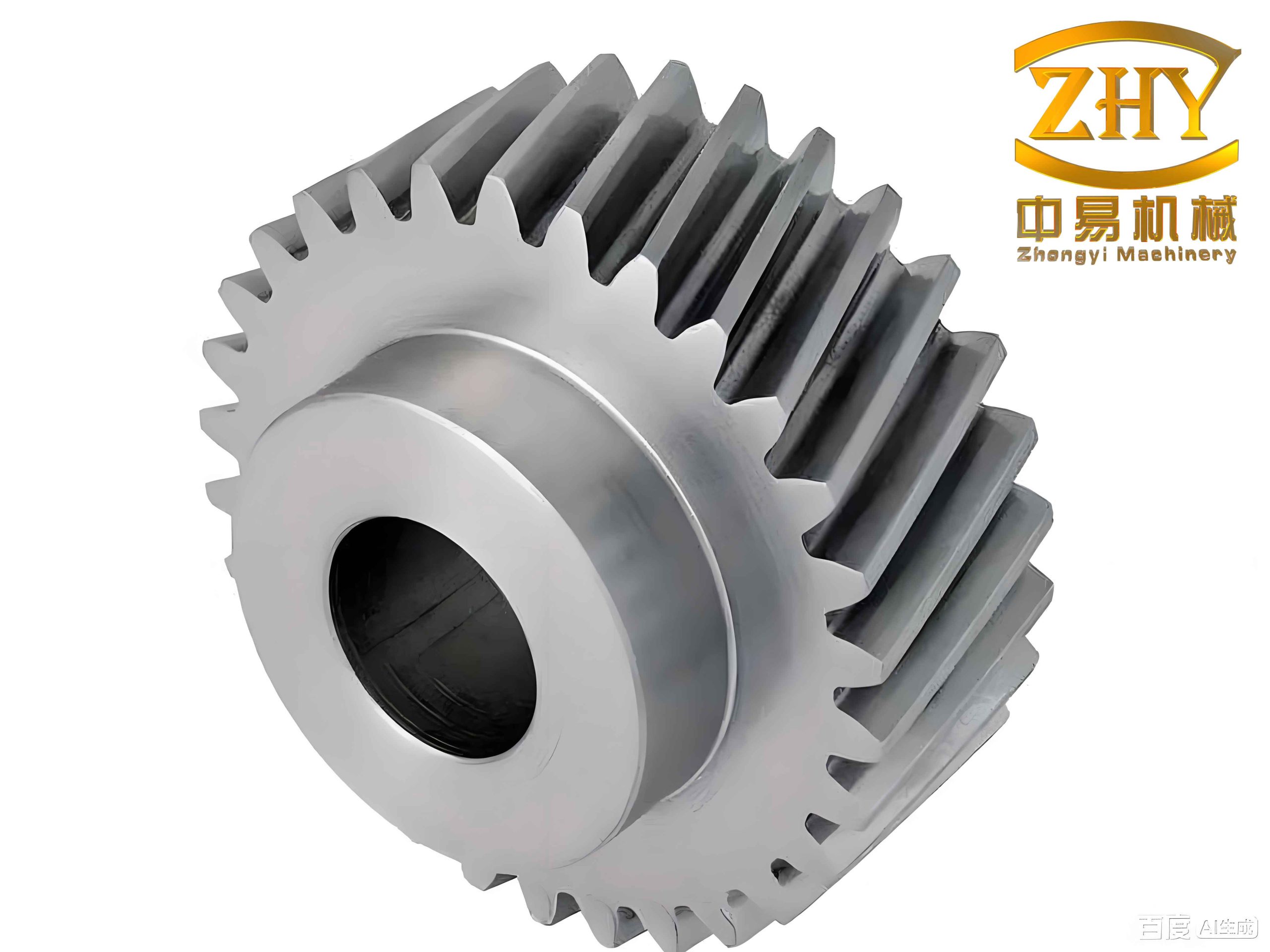
I treat the helical gear pair as a dynamic system in which the first tooth pair experiences out-of-line impact, and this impact changes the angular velocities of the driving and driven gears. The velocity difference then induces additional impact on the second and third tooth pairs along the internal mesh line. This multi-tooth impact process is central to my analysis. I also account for flash temperature because high sliding velocity and heavy load generate significant heat at the tooth surface. The resulting thermal deformation modifies the tooth profile, shifts the impact point, and increases the impact excitation. Finally, I study how impact excitation changes the time-varying friction force and the dynamic contact force, and I develop a software tool that integrates the complete calculation procedure.
Analytical Framework for Multi-Tooth Impact Excitation
In my analytical framework, I first determine the actual impact point of the first tooth pair. The theoretical meshing line is defined by the base circle and the pressure angle. Because the gear pair deforms under load, the base pitch of the driving gear and the driven gear no longer remain identical. The driven gear tooth tip therefore contacts the driving gear flank before the theoretical contact point. I use the inversion method to locate the out-of-line impact point. The total deformation along the line of action is written as
$$\delta_{\Sigma}=\delta_1+\delta_2+\delta_c$$
where \(\delta_1\) and \(\delta_2\) are the bending deflections of the driving and driven gears, and \(\delta_c\) is the Hertzian contact deformation. The load deformation angle is then
$$\phi=\frac{\delta_{\Sigma}}{r_{b2}}$$
where \(r_{b2}\) is the base radius of the driven gear. The geometry of the impact point involves the addendum radius, the center distance, the pressure angle, and the rotation angle. I solve the resulting geometric equations to obtain the impact radius \(r_{O1D}\). This impact radius defines the out-of-line contact position for the first tooth pair of the helical gears.
Because helical gears have an inclined contact line, the impact does not occur uniformly across the entire face width. I use a slicing method and divide the helical gear into a finite number of independent thin spur gear slices. Each slice has a small face width \(\Delta x\). For a slice located at position \(i\), the impact radius is
$$r_{Di}=\sqrt{r_{b1}^{2}+\left(L_{N1E}+L_{EDi}\right)^{2}}$$
where \(L_{N1E}\) is the theoretical distance from the base tangent point to the theoretical entering point, and \(L_{EDi}\) is the additional distance along the line of action. The normal impact velocity for each slice is
$$\Delta v_{ni}=v_{n1i}-v_{n2i}=\omega_1 r_{b1}-\omega_2 r’_{b2i}$$
where \(\omega_1\) and \(\omega_2\) are the angular velocities of the driving and driven helical gears, \(r_{b1}\) is the driving gear base radius, and \(r’_{b2i}\) is the instantaneous driven gear base radius at the slice. The impact kinetic energy of the first tooth pair is obtained from the sliced masses and the normal velocity difference.
The maximum impact force for each slice is calculated from impact mechanics. The equivalent mass on the line of action for each slice involves the rotary inertia and the base radius. The maximum slice impact force is expressed as
$$F_{si}=\sqrt{\frac{\Delta x\,J_1J_2\,\Delta v_{ni}^{2}}{\left(J_1(r’_{b2i})^{2}+J_2r_{b1}^{2}\right)q_{si}}}$$
where \(J_1\) and \(J_2\) are the moments of inertia of the driving and driven helical gears, and \(q_{si}\) is the combined compliance of the slice, including bending and contact compliance. The total maximum impact force of the first tooth pair is obtained by integrating along the contact line:
$$F_{sm1}=\int_{0}^{L_1}F_{si}\,dx$$
I assume the impact force follows a half-sine pulse. Thus, the impact force of the first tooth pair is
$$F_{s1}(t)=F_{sm1}\sin\left(\frac{\pi t}{t_{s1}}\right)=F_{sm1}\sin(\omega_{s1}t)$$
where \(t_{s1}\) is the impact duration and \(\omega_{s1}=\pi/t_{s1}\). The impact duration is determined from the impulse-momentum theorem. The result shows that the first tooth pair produces the largest impact excitation because it directly experiences out-of-line contact. The impact force depends strongly on rotational speed, input torque, module, and face width.
Energy Conservation and Induced Velocity Difference
After the first tooth pair impacts, the normal velocity component is reduced, and the impact kinetic energy is transferred between the driving and driven helical gears. I use energy conservation to calculate the velocity perturbation. The impact kinetic energy is
$$E_k=\frac{1}{2}\sum_{i=1}^{N}\frac{J_1J_2}{J_1(r’_{b2i})^{2}+J_2r_{b1}^{2}}\Delta v_{ni}^{2}$$
The tangential impact velocity also produces a tangential impulse. I assume this tangential kinetic energy is dissipated by friction. The tangential impulse energy is
$$W_f=\frac{1}{2}\sum_{i=1}^{N}\frac{J_1J_2}{J_1(r’_{b2i})^{2}+J_2r_{b1}^{2}}\Delta v_{\tau i}^{2}$$
The tangential velocity difference is related to the normal velocity difference and the pressure angle at the impact point. The velocity changes on the impacted side of the helical gears, while the other side remains nearly unchanged. Using the sliced representation, I write the velocity of each slice after impact as a linear distribution across the face width. The post-impact velocities of the driving and driven gears are obtained from
$$\frac{1}{2}m_{\mathrm{red1}}v_1^{2}+E_k+W_f=\frac{1}{2}m_{\mathrm{red1}}(v’_1)^{2}$$
$$\frac{1}{2}m_{\mathrm{red2}}v_2^{2}+E_k=\frac{1}{2}m_{\mathrm{red2}}(v’_2)^{2}$$
where \(m_{\mathrm{red1}}\) and \(m_{\mathrm{red2}}\) are the equivalent masses of the driving and driven helical gears on the line of action. The velocity change creates a small backlash on the impacted side. I assume the backlash varies linearly across the face width. The maximum backlash after impact is
$$L_{\max}=\frac{(v’_1+v_1)t_{s1}}{2}-\frac{(v’_2+v_2)t_{s1}}{2}$$
This backlash affects the re-engagement of the second and third tooth pairs. The second tooth pair and the third tooth pair are already in contact along the internal mesh line. Because the first tooth pair impact changes the angular velocities, the second and third tooth pairs experience a velocity difference and therefore generate internal impact forces.
Internal Impact on the Second and Third Tooth Pairs
The contact line lengths of the second and third tooth pairs are determined from the overlap ratio and the face width. For helical gears, the contact line length varies with time because of the axial overlap. The second tooth pair contact line and the third tooth pair contact line are expressed as
$$L_2=\frac{p_{bt}\,\theta_1-r_{b1}\beta_b}{\sin\beta_b}$$
$$L_3=\frac{b-p_{bt}}{\cos\beta_b}-\frac{2p_{bt}\,\theta_1-r_{b1}\beta_b}{\sin\beta_b}$$
where \(p_{bt}\) is the transverse base pitch, \(b\) is the face width, \(\beta_b\) is the base helix angle, and \(\theta_1\) is the rotation angle of the driving helical gear. The velocity difference for the second tooth pair is calculated after the first impact. The driving gear tends to accelerate because the contact force drops, while the driven gear tends to decelerate. The re-engagement velocity difference is
$$v_{sj}=v_{1j}-v_{2j}$$
where \(v_{1j}\) and \(v_{2j}\) are the velocities of the driving and driven slices after the free-flight interval. The maximum impact force of the second tooth pair is obtained by integrating the slice impact forces along the contact line:
$$F_{sm2}=\int_{0}^{L_2}F_{sj}\,dy$$
Similarly, the third tooth pair impact force is
$$F_{sm3}=\int_{0}^{L_3}F_{sj}\,dz$$
The total multi-tooth impact excitation of the helical gears is
$$F_{sm}=F_{s1}+F_{s2}+F_{s3}$$
I apply this method to a representative high-speed heavy-load involute helical gear pair. The basic parameters are listed in Table 1. The calculated impact results are summarized in Table 3. The first tooth pair impact is 7114.3 N, the second tooth pair impact is 3092.2 N, and the third tooth pair impact is 1406.1 N. The first tooth pair is larger because it directly experiences out-of-line impact. The second and third tooth pairs are induced by the velocity fluctuation caused by the first impact. The third tooth pair is smaller because its contact line is shorter as it approaches disengagement.
| Parameter | Driving gear | Driven gear |
|---|---|---|
| Number of teeth | 41 | 161 |
| Normal module (mm) | 12 | 12 |
| Normal pressure angle (deg) | 20 | 20 |
| Helix angle (deg) | 12 | -12 |
| Face width (mm) | 185 | 180 |
| Center distance (mm) | 1250 | 1250 |
| Addendum coefficient | 1 | 1 |
| Clearance coefficient | 0.4 | 0.4 |
| Input speed (rpm) | 3000 | — |
| Input power (kW) | 2720 | — |
Temperature Effects on Impact Excitation
High-speed heavy-load operation generates significant frictional heat at the tooth surface. The surface temperature of the helical gears consists of the bulk temperature and the flash temperature. The bulk temperature is reached after the system stabilizes, while the flash temperature is a transient local rise caused by sliding. I use the Blok flash temperature theory to calculate the tooth surface contact temperature. The flash temperature is
$$T_f(t)=\frac{\zeta\mu(t)F_e\left|v_1(t)-v_2(t)\right|}{\left(\sqrt{g_1\rho_1c_1v_1(t)}+\sqrt{g_2\rho_2c_2v_2(t)}\right)B(t)}$$
where \(\zeta\) is the flash temperature coefficient, \(\mu(t)\) is the time-varying friction coefficient, \(F_e\) is the load per unit face width, \(v_1(t)\) and \(v_2(t)\) are the tangential velocities of the driving and driven helical gears, \(g_1\) and \(g_2\) are thermal conductivities, \(\rho_1\) and \(\rho_2\) are densities, \(c_1\) and \(c_2\) are specific heats, and \(B(t)\) is the contact band half-width. The tangential velocities are
$$v_1(t)=\omega_1\left(r_1\sin\alpha-L_{PC}\right)$$
$$v_2(t)=\omega_2\left(r_2\sin\alpha+L_{PC}\right)$$
where \(L_{PC}\) is the distance from the mesh point to the pitch point. The relative sliding velocity is
$$v_s(t)=v_1(t)-v_2(t)$$
The contact band half-width is obtained from Hertzian contact theory:
$$B(t)=\kappa\sqrt{\frac{2\left(1-\nu^{2}\right)F_nR(t)}{Eb}}$$
where \(\kappa\) is a calculation coefficient, \(\nu\) is Poisson’s ratio, \(E\) is the elastic modulus, \(R(t)\) is the equivalent curvature radius, and \(F_n\) is the normal load. The equivalent curvature radius is
$$R(t)=\frac{R_1(t)R_2(t)}{R_1(t)+R_2(t)}$$
I also use a time-varying friction coefficient model that considers the entrainment velocity, slide-to-roll ratio, maximum contact pressure, lubricant viscosity, and surface roughness. The entrainment velocity is
$$v_e(t)=\frac{v_1(t)+v_2(t)}{2}$$
The slide-to-roll ratio is
$$SR(t)=\frac{2\left(v_1(t)-v_2(t)\right)}{v_1(t)+v_2(t)}$$
The maximum contact pressure is
$$P_{\max}=\sqrt{\frac{F_nE}{2\pi b R(t)}}$$
The lubricant viscosity depends on temperature and pressure. I use a free-volume viscosity model to describe the viscosity-temperature effect. The viscosity-temperature equation is
$$\eta(T)=\eta_0\exp\left[\frac{B_0}{R_0}\left(\frac{1}{V(T)}-1\right)\right]$$
where \(V(T)\) is the relative free volume. The time-varying friction coefficient in the elastohydrodynamic lubrication state is then calculated from
$$\mu_{EL}(t)=e^{f(SR,P_{\max},\eta_0,S)}P_{\max}^{b_1}SR(t)^{b_2}v_e(t)^{b_3}\eta_0^{b_4}R(t)^{b_5}$$
The coefficients \(b_1\) to \(b_9\) are empirical parameters. The flash temperature increases sharply at the beginning of meshing, decreases as the sliding velocity decreases, reaches a minimum near the pitch point, and then rises again after the pitch point. I calculate the flash temperature for three rotational speeds: 1000 rpm, 2000 rpm, and 3000 rpm. As the speed increases, the relative sliding velocity increases, and the flash temperature rises. This temperature directly affects the tooth profile because thermal expansion changes the effective tooth shape.
The thermal deformation of the tooth profile is calculated from the flash temperature and the base circle thermal expansion. The base circle thermal deformation is
$$u_b=\frac{\lambda r_b}{2}\left[T(r_b)-T(r_0)\right]+\frac{\lambda r_b}{2}\frac{1+\nu}{1-\nu}\left[T(r_b)-T(r_0)\right]$$
where \(\lambda\) is the linear expansion coefficient, \(r_b\) is the base radius, \(r_0\) is the shaft radius, \(T(r_b)\) is the base circle temperature, and \(T(r_0)\) is the shaft temperature. The actual involute profile after thermal deformation is described by
$$r_k=r_b+u_b+\frac{T_f\lambda r_b\cos\alpha_k}{\cos\alpha_k}$$
$$\theta_k=\tan\alpha_k-\alpha_k-\frac{T_f\lambda S}{2r_k^{2}}$$
where \(\alpha_k\) is the actual pressure angle after thermal deformation and \(S\) is the tooth thickness on the pitch circle. The thermal deformation of the tooth profile is therefore
$$\delta_T=\frac{T_f\lambda r_b}{r}\left[2\cos\alpha_k-2\cos\alpha_{k1}+\frac{S}{r}\left(\mathrm{inv}\alpha_k-\mathrm{inv}\alpha_{k1}\right)\right]$$
The total deformation along the line of action, including temperature, becomes
$$\delta_{\Sigma}’=\delta_1+\delta_2+\delta_c+\delta_T$$
The modified load deformation angle is
$$\phi’=\frac{\delta_{\Sigma}’}{r_{b2}+u_b}$$
I substitute \(\phi’\) into the impact point equations and recalculate the impact radius. The new impact radius produces a larger normal velocity difference, which increases the impact excitation. The temperature-modified impact results are compared with the isothermal results in Table 3. The first tooth pair impact increases from 7114.3 N to 8264.7 N, an increase of 13.93%. The second tooth pair impact increases from 3092.2 N to 3460.9 N, an increase of 10.65%. The third tooth pair impact increases from 1406.1 N to 1573.5 N, an increase of 10.64%. Therefore, tooth surface temperature has a strong effect on the first tooth pair impact and a moderate effect on the induced impacts of the second and third tooth pairs.
| Tooth pair | Without temperature (N) | With temperature (N) | Increase (%) |
|---|---|---|---|
| First tooth pair | 7114.3 | 8264.7 | 13.93 |
| Second tooth pair | 3092.2 | 3460.9 | 10.65 |
| Third tooth pair | 1406.1 | 1573.5 | 10.64 |
Influence of Impact on Meshing State
The impact excitation of helical gears changes the meshing state. I evaluate two important consequences: the time-varying friction force and the dynamic contact force. The time-varying contact line length is first calculated. For helical gears, the total contact line length depends on the transverse contact ratio \(\varepsilon_{\alpha}\) and the overlap ratio \(\varepsilon_{\beta}\). If \(\varepsilon_{\alpha}\ge\varepsilon_{\beta}\), the maximum contact line length is
$$L_{\max}=\frac{b}{\cos\beta_b}$$
If \(\varepsilon_{\alpha}<\varepsilon_{\beta}\), the maximum contact line length is also determined by the face width and base helix angle, but the length variation follows a different sequence. The single tooth contact line length is
$$L(t)=
\begin{cases}
L_{\max}t/(\varepsilon_{\beta}t_c), & 0\le t\le \varepsilon_{\beta}t_c\\
L_{\max}, & \varepsilon_{\beta}t_c\le t\le \varepsilon_{\alpha}t_c\\
L_{\max}(\varepsilon_{\gamma}-t/t_c)/(\varepsilon_{\gamma}-\varepsilon_{\alpha}), & \varepsilon_{\alpha}t_c\le t\le \varepsilon_{\gamma}t_c
\end{cases}$$
where \(\varepsilon_{\gamma}=\varepsilon_{\alpha}+\varepsilon_{\beta}\) and \(t_c\) is the interval between successive tooth engagements. The total contact line length is the sum of the individual tooth contact lines:
$$L_{\mathrm{total}}(t)=\sum_{i=1}^{M}L_i(t)$$
Because the total contact ratio is not an integer, the helical gears alternate between two-tooth and three-tooth contact. This produces a periodic variation in the total contact line length. I calculate the friction coefficient under three lubrication states: impact friction, mixed lubrication, and elastohydrodynamic lubrication. The impact friction occurs during the out-of-line impact period. The average impact friction coefficient is
$$\mu_I=\left|\frac{\Delta V_{D2\tau}}{\Delta V_{D2n}}\right|$$
where \(\Delta V_{D2\tau}\) is the tangential impact velocity and \(\Delta V_{D2n}\) is the normal impact velocity. The impact friction coefficient is high because the oil film is destroyed and the tooth surfaces experience dry contact. After the out-of-line impact, the lubrication state transitions from mixed lubrication to elastohydrodynamic lubrication. The mixed lubrication friction coefficient is written as a weighted sum:
$$\mu_{ML}=\lambda_f\mu_{EL}+(1-\lambda_f)\mu_I$$
where \(\lambda_f\) is the load distribution factor. The minimum oil film thickness is
$$h_{\min}=2.69R U^{0.67}G^{0.53}W^{-0.67}$$
where \(U\) is the dimensionless speed parameter, \(G\) is the dimensionless material parameter, and \(W\) is the dimensionless load parameter. The friction force on each slice is
$$F_{fj}(t)=\mu_j(t)\frac{F_n}{\cos\beta}\frac{\Delta x}{L(t)}$$
The total friction force of the helical gears is
$$F_f(t)=\sum_{j=1}^{m}F_{fj}(t)$$
The friction torque on the driving and driven helical gears is
$$T_{f1}(t)=\sum_{j=1}^{m}F_{fj}(t)L_{1j}(t)$$
$$T_{f2}(t)=\sum_{j=1}^{m}F_{fj}(t)L_{2j}(t)$$
I compare the friction force with and without impact. Without impact, the mean friction force of the helical gears is 7.7 N. With impact, the mean friction force is -206.1 N. The negative sign indicates a change in direction. Without impact, the friction force above the pitch line is slightly larger than the friction force below the pitch line, and the two sides largely cancel each other. With impact, the friction force below the pitch line increases because the oil film is disrupted at the beginning of meshing. The friction balance is lost, and the total friction force increases and reverses direction. This reduces the smoothness of power transmission and can increase vibration and noise.
| Condition | Mean friction force (N) | Maximum single-tooth friction force (N) |
|---|---|---|
| Without impact | 7.7 | -1563.5 |
| With impact | -206.1 | -1778.4 |
I also establish an eight-degree-of-freedom bending-torsion-axial coupled dynamic model of the helical gear transmission system. The generalized displacement vector is
$$q=\begin{bmatrix}x_1 & y_1 & z_1 & \theta_1 & x_2 & y_2 & z_2 & \theta_2\end{bmatrix}^{T}$$
The relative displacement along the normal direction is
$$\delta_n=(x_1-x_2)\sin\alpha+(y_1-y_2)\cos\alpha+(r_1\theta_1-r_2\theta_2)\cos\beta+(z_1-z_2)\sin\beta-e(t)$$
where \(e(t)\) is the transmission error. The dynamic mesh force is
$$F_n=k_m(t)\delta_n+c_m\dot{\delta}_n+F_s(t)$$
where \(k_m(t)\) is the time-varying mesh stiffness, \(c_m\) is the mesh damping, and \(F_s(t)\) is the impact excitation. The dynamic equations are
$$m_1\ddot{x}_1+c_{1x}\dot{x}_1+k_{1x}x_1=F_x$$
$$m_1\ddot{y}_1+c_{1y}\dot{y}_1+k_{1y}y_1=F_y$$
$$m_1\ddot{z}_1+c_{1z}\dot{z}_1+k_{1z}z_1=F_z$$
$$I_1\ddot{\theta}_1=T_1-F_y r_{b1}-F_s r_{b1}$$
$$m_2\ddot{x}_2+c_{2x}\dot{x}_2+k_{2x}x_2=-F_x$$
$$m_2\ddot{y}_2+c_{2y}\dot{y}_2+k_{2y}y_2=-F_y$$
$$m_2\ddot{z}_2+c_{2z}\dot{z}_2+k_{2z}z_2=-F_z$$
$$I_2\ddot{\theta}_2=T_2+F_y r_{b2}+F_s r_{b2}$$
I solve these equations using a fourth-order variable-step Runge-Kutta method. The contact force is then obtained from the dynamic mesh force. The results are listed in Table 5. Without impact, the mean contact force is 40075 N and the amplitude is 38071 N. With impact, the mean contact force is 40180 N and the amplitude is 36751 N. The mean contact force increases by 0.26%, while the amplitude decreases by 3.47%. In the frequency domain, the impact increases the contact force amplitude at two times, three times, and four times the meshing frequency, while it decreases the contact force amplitude at the meshing frequency. Therefore, impact excitation has a limited effect on the average load capacity of the helical gears, but it significantly changes the dynamic contact force components.
| Condition | Mean contact force (N) | Amplitude (N) | Change in mean (%) | Change in amplitude (%) |
|---|---|---|---|---|
| Without impact | 40075 | 38071 | — | — |
| With impact | 40180 | 36751 | 0.26 | -3.47 |
Parameter Influence on Impact Excitation
I study the influence of input speed, input torque, and normal module on the impact excitation of helical gears. The results are summarized in Table 7. As the input speed increases, the angular velocity of the helical gears increases, the normal impact velocity becomes larger, and the impact excitation increases. As the input torque increases, the normal load per unit face width increases, the gear deformation increases, and the out-of-line impact becomes more severe. As the normal module increases, the impact radius increases, which increases the impact velocity of the first tooth pair. However, the mass of the helical gears also increases, which reduces the velocity fluctuation caused by the first impact. Therefore, the first tooth pair impact increases with module, while the induced impacts on the second and third tooth pairs decrease with module. These trends show that the impact excitation of helical gears is a combined result of geometric parameters and operating conditions.
| Parameter | Effect on first tooth pair impact | Effect on induced tooth pair impacts |
|---|---|---|
| Input speed increases | Increases | Increases |
| Input torque increases | Increases | Increases |
| Normal module increases | Increases | Decreases |
Software Implementation
I develop a software tool for the impact excitation calculation of high-speed heavy-load involute helical gears. The software is built on a matrix-based numerical computing platform with a graphical user interface. The main interface contains an entry button and an exit button. The parameter input interface contains gear geometry parameters, operating conditions, material properties, and thermal parameters. The calculation result interface contains three modules: multi-tooth impact, tooth surface friction, and tooth surface contact force. Each module displays curves for the condition with and without the considered effect. The software also allows data export for post-processing.
| Module | Function | Output |
|---|---|---|
| Gear parameter input | Enter number of teeth, module, pressure angle, helix angle, face width, center distance | Validated parameter set |
| Operating condition input | Enter speed, power, torque, material, thermal parameters | Complete calculation case |
| Multi-tooth impact | Calculate first, second, and third tooth pair impacts | Impact force curves with and without temperature |
| Tooth surface friction | Calculate time-varying friction coefficient and friction force | Friction force curves with and without impact |
| Tooth surface contact force | Solve coupled dynamic model and obtain contact force | Time-domain and frequency-domain contact forces |
I test the software with the same parameter set used in the analytical calculation. The software reproduces the first tooth pair impact of 7114.3 N, the second tooth pair impact of 3092.2 N, and the third tooth pair impact of 1406.1 N. When temperature is included, the software produces 8264.7 N, 3460.9 N, and 1573.5 N for the three tooth pairs. The friction force mean changes from 7.7 N to -206.1 N when impact is included. The contact force mean changes from 40075 N to 40180 N, and the amplitude changes from 38071 N to 36751 N. The software runs without errors and produces results consistent with the analytical method. Therefore, the software provides a fast and integrated tool for evaluating the impact excitation of helical gears.
Discussion
The results of my study show that the impact excitation of high-speed heavy-load involute helical gears is a multi-tooth process. The first tooth pair experiences out-of-line impact because of load deformation and geometric error. This impact changes the angular velocities of the driving and driven helical gears. The velocity difference then induces internal impact on the second and third tooth pairs. The first tooth pair impact is the largest, the second tooth pair impact is intermediate, and the third tooth pair impact is the smallest. The contact line length of each tooth pair controls the magnitude of the induced impact. The third tooth pair has a shorter contact line because it is close to disengagement, so its impact is smaller.
Temperature has a significant effect on the impact excitation of helical gears. The flash temperature rises sharply at the beginning of meshing, decreases near the pitch point, and rises again after the pitch point. The thermal deformation changes the tooth profile and shifts the impact point. When temperature is included, the first tooth pair impact increases by 13.93%, the second tooth pair impact increases by 10.65%, and the third tooth pair impact increases by 10.64%. This indicates that thermal effects should not be ignored in high-speed heavy-load helical gears. The temperature effect is strongest for the first tooth pair because the impact point is most sensitive to profile change. The induced impacts on the second and third tooth pairs are also increased, but their relative change is smaller.
Impact excitation also changes the meshing state of helical gears. The time-varying friction force is strongly affected. Without impact, the friction force above and below the pitch line nearly cancel each other. With impact, the oil film at the beginning of meshing is disrupted, and the friction force below the pitch line increases. The total friction force changes direction and becomes much larger in magnitude. This can increase vibration and noise and reduce transmission smoothness. The dynamic contact force is also affected. The mean contact force changes only slightly, but the amplitude decreases by 3.47%. In the frequency domain, the impact increases the contact force components at two times, three times, and four times the meshing frequency, and decreases the component at the meshing frequency. These changes are important for vibration and noise control in helical gears.
Conclusions
I have developed an analytical method for the multi-tooth impact excitation of high-speed heavy-load involute helical gears. The main conclusions are as follows.
First, I determined the out-of-line impact point using the inversion method and calculated the first tooth pair impact force using a sliced impact model. The first tooth pair impact was 7114.3 N for the representative case. I then used energy conservation to calculate the velocity perturbation caused by the first impact. The velocity perturbation induced internal impact on the second and third tooth pairs. The second tooth pair impact was 3092.2 N, and the third tooth pair impact was 1406.1 N. The first tooth pair impact was the largest, and the third tooth pair impact was the smallest because of the shorter contact line.
Second, I calculated the tooth surface flash temperature using the Blok theory. The flash temperature increased with rotational speed and sliding velocity. I derived the thermal deformation of the tooth profile and incorporated it into the impact point calculation. When temperature was included, the first tooth pair impact increased by 13.93%, the second tooth pair impact increased by 10.65%, and the third tooth pair impact increased by 10.64%. Therefore, temperature must be considered in the impact excitation analysis of high-speed heavy-load helical gears.
Third, I studied the influence of impact on the meshing state. The impact changed the friction force from a mean of 7.7 N to -206.1 N. The friction balance above and below the pitch line was lost because the oil film was disrupted at the beginning of meshing. The impact also changed the dynamic contact force. The mean contact force increased by 0.26%, while the amplitude decreased by 3.47%. The impact increased the contact force components at two times, three times, and four times the meshing frequency. These results show that impact excitation affects both friction and contact force in helical gears.
Fourth, I developed a graphical software tool for the impact excitation calculation of high-speed heavy-load involute helical gears. The software includes parameter input, multi-tooth impact calculation, friction calculation, and contact force calculation. The software reproduces the analytical results and provides a fast and integrated design tool. My research provides a theoretical basis for reducing tooth breakage, lowering transient noise, and improving the reliability of high-speed heavy-load helical gears.
| Research aspect | Method | Key result |
|---|---|---|
| Out-of-line impact | Inversion method and sliced impact model | First tooth pair impact = 7114.3 N |
| Induced impact | Energy conservation and velocity difference | Second = 3092.2 N, third = 1406.1 N |
| Temperature effect | Blok flash temperature and thermal deformation | First impact increases by 13.93% |
| Friction effect | Impact friction, mixed lubrication, elastohydrodynamic lubrication | Mean friction changes from 7.7 N to -206.1 N |
| Contact force effect | Coupled bending-torsion-axial dynamic model | Mean +0.26%, amplitude -3.47% |
| Software tool | Graphical interface and numerical solver | Integrated calculation and data export |
In my future work, I plan to extend the model to include more sources of system error and tooth deformation. I also intend to study the effect of impact on the temperature field of the entire helical gear transmission system. In addition, I will examine the coupling between impact, friction, and contact force under more complex operating conditions. These extensions will further improve the prediction accuracy of impact excitation in high-speed heavy-load helical gears.