
In this study, I focus on the casting forming design and optimization of herringbone face gears, which are a promising transmission component for heavy-duty industrial applications. Unlike conventional spiral bevel gears, herringbone face gears offer higher load capacity, a more compact structure, and improved tolerance to assembly errors. However, the complex three-dimensional geometry of herringbone face gears makes conventional machining extremely difficult and inefficient. To overcome these manufacturing challenges, I adopt lost foam casting as the primary forming method and systematically investigate the forming mechanism, process design, numerical simulation, and parameter optimization. The main contributions of my work are summarized in the following sections.
1. Tooth Surface Derivation and Modification of Herringbone Face Gears
I begin by establishing a mathematical model of the pinion tooth surface based on spatial meshing theory. By using coordinate transformation, I analyze the relative position and orientation of the gear pair in space and derive the parametric equations for the herringbone tooth surface. The coordinate systems used for the face gear generation are defined as follows: the fixed reference frames are denoted by \(S_{10}(x_{10},y_{10},z_{10})\) and \(S_{20}(x_{20},y_{20},z_{20})\), while the moving reference frames are \(S_1(x_1,y_1,z_1)\) and \(S_2(x_2,y_2,z_2)\). The transformation matrices are given by:
$$M_{10,1} = \begin{bmatrix} \cos\xi_1 & \sin\xi_1 & 0 & 0 \\ -\sin\xi_1 & \cos\xi_1 & 0 & 0 \\ 0 & 0 & 1 & 0 \\ 0 & 0 & 0 & 1 \end{bmatrix}$$
$$M_{20,10} = \begin{bmatrix} 0 & 0 & 1 & L_0 \\ 0 & 1 & 0 & 0 \\ -1 & 0 & 0 & 0 \\ 0 & 0 & 0 & 1 \end{bmatrix}$$
$$M_{2,20} = \begin{bmatrix} \cos\xi_2 & \sin\xi_2 & 0 & 0 \\ -\sin\xi_2 & \cos\xi_2 & 0 & 0 \\ 0 & 0 & 1 & 0 \\ 0 & 0 & 0 & 1 \end{bmatrix}$$
The overall transformation from the pinion coordinate system to the face gear coordinate system is then:
$$M_{2,1} = M_{2,20} M_{20,10} M_{10,1}$$
For the pinion involute tooth surface, I use the following parametric equations:
$$\begin{cases} x_1 = r_{bs}[\cos(\theta_1 + \eta_1) + \theta_1 \sin(\theta_1 + \eta_1)] \\ y_1 = r_{bs}[\sin(\theta_1 + \eta_1) – \theta_1 \cos(\theta_1 + \eta_1)] \\ z_1 = 0 \end{cases}$$
where \(r_{bs}\) is the base circle radius, \(\eta_1\) is the angle parameter, and \(\theta_1\) is the position parameter on the tooth surface. For the helical pinion, the tooth surface equations become:
$$\begin{cases} x_{1ot} = r_{bs}[\cos(\theta_1 + \eta_1 + \lambda_1) + \theta_1 \sin(\theta_1 + \eta_1 + \lambda_1)] \\ y_{1ot} = r_{bs}[\sin(\theta_1 + \eta_1 + \lambda_1) – \theta_1 \cos(\theta_1 + \eta_1 + \lambda_1)] \\ z_{1ot} = p_1 \lambda_1 \end{cases}$$
where \(\lambda_1\) is the helical angle and \(p_1\) is the helical parameter. The meshing equation for the face gear generation is derived as:
$$f(\theta_1,\lambda_1,\varphi_1) = \cos\beta_b \cos\alpha_b \sin(\varphi_1 + \lambda_1) – \sin\beta_b \cos(\varphi_1 + \lambda_1) + \frac{i_{21}p_1}{r_{bs}} \cos\beta_b – \frac{i_{21}r_{bs}}{r_{bs}} \cos\beta_b \sin\alpha_b = 0$$
Solving this equation yields the tooth surface of the herringbone face gear. The inner and outer tooth surfaces are obtained by mapping the pinion tooth surface through the transformation matrix:
$$\begin{cases} f(\theta_1,\lambda_1,\varphi_1) = 0 \\ r_{2it/2ot} = M_{2,1} r_{1it/1ot} \end{cases}$$
To address the stress concentration at the tooth tip, I apply an active topological modification strategy. The modification curve is chosen as a parabola \(y = ax^2\) with \(a = 0.8\), and the modification amount is set to \(m = 0.8\,\text{mm}\). The modified tooth surface is obtained by subtracting \(m\) from the original \(x\)-coordinate while keeping \(y\) and \(z\) unchanged. The contact path is preset to run from the lower part of the inner root to the upper part of the outer tip. After modification, the maximum contact stress is reduced by 44% compared to the unmodified case. The optimal modification amount is determined to be 0.8 mm, as shown in Table 1.
| Modification amount (mm) | Maximum contact stress (MPa) | Contact path consistency |
|---|---|---|
| 0.5 | 235 | Partially consistent |
| 0.6 | 210 | Partially consistent |
| 0.7 | 180 | Mostly consistent |
| 0.8 | 96 | Fully consistent |
| 0.9 | 150 | Deviation at tip |
The three-dimensional model of the herringbone face gear is then built in UG software by importing the modified tooth surface point cloud, fitting the surface, and arraying the single tooth. A five-tooth simplified model is used for finite element analysis in ABAQUS. The contact stress distributions before and after modification are compared. Before modification, severe edge contact occurs at the tooth ends, with stress concentrated at the tip. After modification, the contact path moves to the middle of the tooth surface, and the stress concentration is significantly alleviated. These results confirm that the active topological modification is effective for herringbone face gears.
2. Casting Process Design for Herringbone Face Gears
The herringbone face gear has a complex geometry with a herringbone-shaped tooth surface, which makes it difficult to form by traditional machining. I select lost foam casting as the forming method because it can produce near-net-shaped complex parts with good surface quality. The material chosen for the gear is ZG30Cr1MnSi1 cast steel, whose chemical composition is listed in Table 2. This material offers high strength, good toughness, and excellent wear resistance, making it suitable for heavy-duty face gears.
| Element | C | Si | Mn | Cr | P | S |
|---|---|---|---|---|---|---|
| Content (%) | 0.27–0.34 | 0.40–0.70 | 0.90–1.20 | 0.50–0.80 | ≤0.035 | ≤0.035 |
The lost foam casting process flow includes pattern preparation, coating, drying, sand filling, vibration compaction, negative pressure application, and pouring. The pattern is made of EPS and STMMA foam. The coating must have good high-temperature resistance, permeability, and adhesion. The sand used is artificial ceramic sand, and a double-layer sand box is selected to ensure uniform negative pressure distribution. The pouring system is designed with a closed-type structure to improve slag inclusion resistance. Two initial schemes are considered: top pouring and bottom pouring. The bottom pouring scheme is preferred because it allows the metal to fill from the bottom upward, which is beneficial for gas escape and slag removal. The gating system dimensions are calculated based on the following equations:
$$S_{\text{choke}} = \frac{G_L}{0.31 \mu t \sqrt{H_P}}$$
$$H_{\text{residual}} \geq L \tan\alpha$$
$$h_{\text{avg}} = h_{\text{inner}} – \frac{p^2}{2C}$$
where \(G_L\) is the total pouring mass, \(\mu\) is the flow coefficient, \(t\) is the pouring time, \(H_P\) is the average static pressure head, \(L\) is the horizontal distance, \(\alpha\) is the pressure angle, \(h_{\text{inner}}\) is the inner gate pressure head, \(p\) is the pattern height above the inner gate, and \(C\) is the total pattern height. The cross-sectional areas of the sprue, runner, and ingate are determined as \(A_{\text{sprue}} = 10.6\,\text{cm}^2\), \(A_{\text{runner}} = 5.3\,\text{cm}^2\), and \(A_{\text{ingate}} = 3.6\,\text{cm}^2\), respectively. The sprue is designed as a vase shape, the runner as a rectangular section, and the ingate as a circular section. The gating system is verified to be reasonable by checking the filling conditions.
3. Numerical Simulation of Lost Foam Casting for Face Gears
I use ProCAST software to simulate the filling and solidification processes of the herringbone face gear casting. The governing equations for the filling process include the continuity equation, the Navier–Stokes equation, and the energy equation. For incompressible fluid, the continuity equation is:
$$\frac{\partial u}{\partial x} + \frac{\partial v}{\partial y} + \frac{\partial w}{\partial z} = 0$$
The energy equation for the filling process is:
$$\rho c_p \left( \frac{\partial T}{\partial t} + u \frac{\partial T}{\partial x} + v \frac{\partial T}{\partial y} + w \frac{\partial T}{\partial z} \right) = \lambda \nabla^2 T + Q$$
For the solidification process, the Fourier heat conduction equation is used:
$$\rho c_p \frac{\partial T}{\partial t} = \frac{\partial}{\partial x}\left( \lambda \frac{\partial T}{\partial x} \right) + \frac{\partial}{\partial y}\left( \lambda \frac{\partial T}{\partial y} \right) + \frac{\partial}{\partial z}\left( \lambda \frac{\partial T}{\partial z} \right) + Q$$
where \(Q = \rho L \frac{\partial f_s}{\partial t}\) is the latent heat source. The Niyama criterion is used to predict shrinkage porosity:
$$\frac{G}{\sqrt{v_c}} \leq C_N$$
where \(G\) is the local temperature gradient, \(v_c\) is the cooling rate, and \(C_N\) is the critical value. The shrinkage cavity and porosity distributions are analyzed for both top and bottom pouring schemes. The results show that the bottom pouring scheme produces fewer defects. For the top pouring scheme, the shrinkage porosity volume fraction reaches 19.25%, with severe defects at the left corner. For the bottom pouring scheme, the defects are mainly located in the runner, and the gear body is nearly free of shrinkage porosity. Therefore, the bottom pouring scheme is selected for further optimization.
4. Response Surface Optimization of Casting Parameters
To minimize the shrinkage porosity in the herringbone face gear casting, I use the response surface method to optimize the pouring temperature, pouring speed, and negative pressure. First, single-factor experiments are conducted to determine the reasonable ranges of each parameter. The results are shown in Table 3. The optimal negative pressure is 0.04 MPa, the optimal pouring speed is 13 s, the optimal pouring temperature is 1600 °C, and the optimal pattern density is 20 kg/cm³.
| Parameter | Range | Optimal value | Minimum shrinkage porosity (%) |
|---|---|---|---|
| Negative pressure (MPa) | 0.035–0.055 | 0.04 | 8.30 |
| Pouring speed (s) | 12–14 | 13 | 8.62 |
| Pouring temperature (°C) | 1520–1640 | 1600 | 9.12 |
| Pattern density (kg/cm³) | 18–22 | 20 | 6.11 |
Based on the single-factor results, I design a Box-Behnken experiment with three factors: pouring temperature (A), pouring speed (B), and negative pressure (C). The factor levels are listed in Table 4. The response is the shrinkage porosity rate \(Y\). The regression model obtained is:
$$Y = 9.07 + 0.1262A – 0.8237B + 0.2275C + 0.3775AB + 0.9750AC + 0.1650BC – 1.58A^2 – 1.35B^2 – 1.20C^2$$
| Level | A: Pouring temperature (°C) | B: Pouring speed (s) | C: Negative pressure (MPa) |
|---|---|---|---|
| -1 | 1550 | 12.5 | 0.04 |
| 0 | 1575 | 13 | 0.045 |
| 1 | 1600 | 13.5 | 0.05 |
The analysis of variance shows that the model is highly significant (\(F = 57.88\), \(p < 0.0001\)), and the lack-of-fit is not significant (\(p = 0.2324\)). The adjusted \(R^2\) is 0.9697, indicating a good fit. The effects of the factors on shrinkage porosity are ranked as follows: pouring speed > negative pressure > pouring temperature. The interaction between pouring temperature and negative pressure is the most significant. The optimal parameters predicted by the model are: pouring temperature = 1600 °C, pouring speed = 13 s, and negative pressure = 0.04 MPa. The predicted shrinkage porosity is 5.03%. Three verification simulations give shrinkage porosity values of 5.12%, 5.07%, and 5.03%, which are in good agreement with the prediction. The optimized casting process significantly reduces the shrinkage porosity in the herringbone face gear casting.
5. Experimental Verification of Herringbone Face Gear Casting
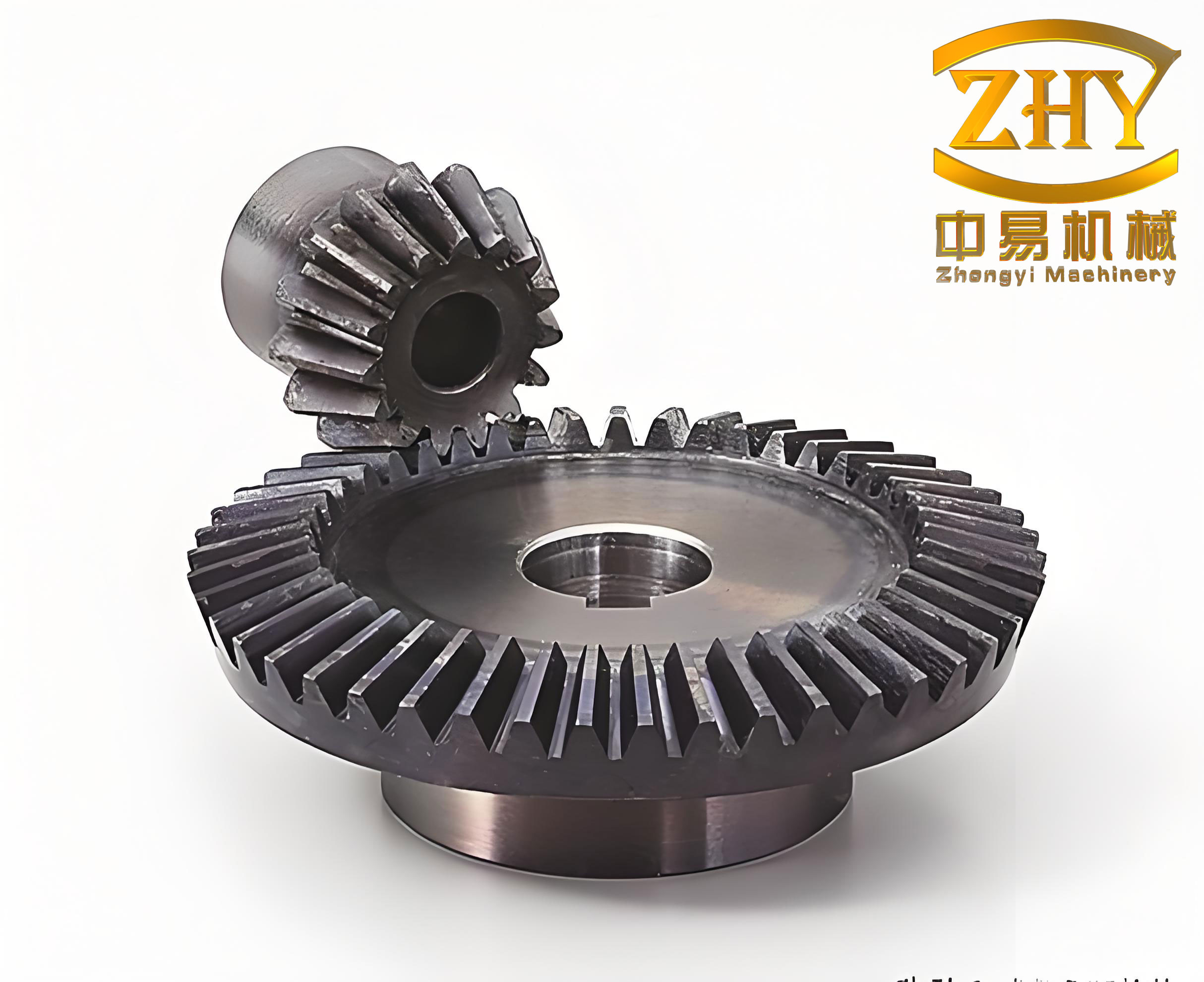
I fabricate the lost foam pattern of the herringbone face gear using CNC milling. The tool path is planned in UG software, and a ball-end milling cutter with a radius of R1 is used for the finishing of the tooth surface. The machining parameters are: spindle speed = 2500 rpm, feed rate = 3000 mm/min, cutting depth = 2 mm, and cutting mode = reciprocating. The pattern is coated with refractory coating, dried, and then placed in the sand box. The pouring is carried out with the optimized parameters. The cast herringbone face gear is shown in the figure below.
After casting, I measure the tooth surface accuracy using a coordinate measuring machine. The maximum normal deviation between the measured tooth surface and the theoretical tooth surface is less than 138 μm, which meets the precision requirements for face gears in general transmission applications. I also perform ultrasonic nondestructive testing to evaluate the internal quality of the casting. The results show that there are slight shrinkage porosities in the central region of the face gear, but no significant defects are found on the tooth surface. The overall quality of the herringbone face gear casting is acceptable.
6. Conclusions
In this study, I have systematically investigated the casting forming design and optimization of herringbone face gears. The following conclusions can be drawn:
(1) A mathematical model of the herringbone face gear tooth surface was established based on spatial meshing theory. An active topological modification method was proposed to reduce stress concentration at the tooth tip. The optimal modification amount was determined to be 0.8 mm, which reduced the maximum contact stress by 44%.
(2) A lost foam casting process was designed for the herringbone face gear. The gating system was calculated and two pouring schemes were compared. The bottom pouring scheme was selected because it produced fewer shrinkage defects.
(3) Numerical simulation of the filling and solidification processes was carried out. The results showed that the bottom pouring scheme had a more stable filling process and a more favorable solidification sequence. The response surface method was used to optimize the pouring temperature, pouring speed, and negative pressure. The optimal parameters were found to be 1600 °C, 13 s, and 0.04 MPa, respectively.
(4) The optimized casting process was verified by experiments. The herringbone face gear casting was successfully produced. The tooth surface accuracy was within 138 μm, and the internal shrinkage porosity was minimal. The results confirm that the proposed casting design and optimization method is effective for manufacturing complex face gears.
In future work, I plan to further improve the casting quality by using multi-physics coupling simulation and intelligent optimization algorithms. I also intend to apply higher-precision inspection methods for three-dimensional quantitative analysis of internal defects in face gears.