
I studied the temperature field of a 20CrMnTi steel spiral bevel gear during hard-tooth surface heat treatment, especially the carburizing, quenching, and tempering stages. My main concern was heat treatment distortion, because distortion directly affects the dimensional accuracy of a spiral bevel gear. I found that nonuniform temperature distributions on the tooth surface and within the internal space are among the strongest drivers of thermal stress and microstructural stress. Therefore, I built a thermal-fluid-solid coupling model to analyze how the temperature field evolves and how it can be made more uniform. I used preheating, stepwise heating, and holding to reduce temperature gradients during carburizing. I also optimized the quenching medium flow field and the quenching parameters to improve temperature uniformity. Through orthogonal experimental variance analysis, I obtained a preferred parameter combination: medium temperature of 100 °C, inlet flow rate of 2 m/s, and quenching temperature of 850 °C. Under this combination, the minimum temperature standard deviations along the tooth length and tooth width directions were 38.68 °C and 38.40 °C, respectively. I verified the reasonableness and accuracy of this combination by coupled numerical simulation and experimental observation. The results provide a useful reference for controlling distortion in a spiral bevel gear during heat treatment.
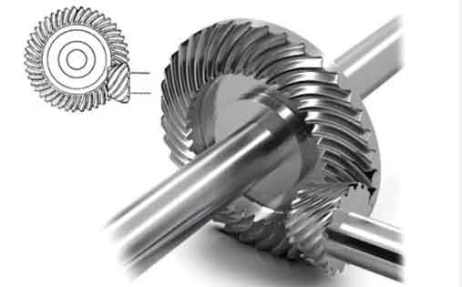
1. Thermo-Fluid-Solid Coupling Model
I treated the hard-tooth surface heat treatment of a spiral bevel gear as a coupled problem involving solid heat conduction, solid-state phase transformation, latent heat release, fluid flow, boiling heat transfer, and interface heat exchange. The spiral bevel gear has a complex geometry, so the temperature field cannot be represented accurately by a one-dimensional or purely empirical model. I therefore combined a temperature-microstructure coupling model for the solid with a fluid heat transfer model for the quenching medium and linked them through a fluid-solid interface. This approach let me capture how the local flow field around the spiral bevel gear changes the local cooling rate and how the phase transformations inside the spiral bevel gear release latent heat and alter the temperature distribution.
1.1 Solid Temperature-Microstructure Coupling Model
For the solid domain, I used the three-dimensional Fourier heat conduction equation with an internal heat source term to represent latent heat from phase transformation. The governing equation I used is:
$$ \operatorname{div}(\lambda \operatorname{grad}T)+Q=\frac{\partial(c_p\rho T)}{\partial t} $$
Here, λ is the thermal conductivity of the material, T is the instantaneous temperature of the spiral bevel gear, Q is the phase transformation latent heat, ρ is density, cp is specific heat capacity, and t is time. I included the latent heat term because the quenching of a spiral bevel gear involves diffusion-controlled transformations and martensitic transformation. If latent heat is ignored, the predicted cooling curves can be too fast and the temperature field can be inaccurate.
I expressed the total latent heat as the sum of contributions from each phase transformation:
$$ Q=\sum_{i=1}^{n}Q_i=\sum_{i=1}^{n}\Delta H_i\frac{dV_i}{dt}, \quad i=1,\dots,n $$
In this equation, ΔHi is the transformation enthalpy of phase i, and Vi is the volume fraction of that phase. For diffusion-controlled transformations such as ferrite, pearlite, bainite, and other diffusional products, I combined the Johnson-Mehl-Avrami equation with the Scheil additivity rule. This allowed me to handle non-isothermal continuous cooling, which is essential for a spiral bevel gear because different locations experience different cooling histories.
The transformation fraction was updated as:
$$ f_{i+1}=1-\exp\left[-b_{i+1}\left(t^*_{i+1}+\Delta t\right)^{n_{i+1}}\right] $$
The virtual transformation time was calculated from the current fraction:
$$ t^*_{i+1}=\left[\frac{-\ln(1-f_i)}{b_{i+1}}\right]^{1/n_{i+1}} $$
I also used the additivity rule to accumulate incubation:
$$ t=\sum_{i=1}^{n}\frac{\Delta t_i}{(t_0)_i}, \quad i=1,\dots,n $$
Here, fi is the transformed volume fraction, ni and bi are transformation kinetics parameters, t*i is the virtual transformation time, Δt is the time increment, and t0 is the incubation period. For non-diffusional martensitic transformation, I used the Koistinen-Marburger equation:
$$ f=1-\exp[-\alpha(M_s-T)] $$
In this equation, f is the martensite volume fraction, α is a kinetics parameter, Ms is the martensite start temperature, and T is the current temperature. I used α = 0.011 in the simulation. This equation is particularly important for the spiral bevel gear surface, where the carbon content is high and the martensite start temperature is depressed by carbon enrichment.
| Symbol | Meaning | Role in the Model |
|---|---|---|
| T | Instantaneous temperature | Primary field variable for the spiral bevel gear |
| λ | Thermal conductivity | Controls heat conduction inside the spiral bevel gear |
| ρ | Density | Affects thermal inertia |
| cp | Specific heat capacity | Controls sensible heat storage |
| Q | Latent heat | Represents phase transformation heat |
| f | Phase fraction | Tracks martensite, bainite, and diffusional products |
| Ms | Martensite start temperature | Determines onset of martensitic transformation |
1.2 Fluid Heat Transfer and Boiling Model
For the quenching medium, I used a boiling heat transfer model to represent the three wall heat flux components: single-phase convection, vaporization, and transient quenching. The total wall heat flux was written as:
$$ q_w=q_{con}+q_{ev}+q_{qui}=h_{con}A_{con}(T_w-T_l)+fN\frac{\pi}{6}d_w^3\rho_g h_{lg}+\frac{2A_b f}{\tau_w}\sqrt{\frac{\lambda_l\rho_l c_{pl}}{\pi}}(T_w-T_l) $$
In this expression, hcon is the single-phase convective heat transfer coefficient, Acon is the fraction of wall area not occupied by bubbles, Ab is the remaining area fraction, Tw is wall temperature, Tl is bulk liquid temperature, dw is bubble departure diameter, f is bubble departure frequency, τw is waiting time, N is nucleation site density, ρg is vapor density, hlg is latent heat of vaporization, and λl, ρl, and cpl are liquid properties. I used this model because the quenching of a spiral bevel gear often passes through film boiling, transition boiling, and nucleate boiling regimes, especially near the tooth tip and root where the local flow can be very different.
1.3 Fluid-Solid Interface Coupling
I coupled the fluid and solid domains through the wall heat flux and interface temperature. The wall heat flux was calculated using a wall function approach:
$$ q_W=\frac{y_p^+}{u_p^*}\frac{T_P^+-T_W^+}{y_P}\mu C_p $$
In this equation, yp+ and Tp+ are dimensionless distance and temperature, yP is the distance from the first near-wall node to the wall, TP is the temperature at that node, TW is wall temperature, μ is dynamic viscosity, and Cp is specific heat capacity. For the interface data exchange, I used Gaussian integration to map variables between nonmatching meshes:
$$ u_s(x)=\sum_{i=1}^{n_s}N_i^s(x)u_s^i $$
$$ \int_{\Gamma_f}N_k^f(x)N_i^s(x)\,dx=\sum_{j=1}^{n_f}\sum_{g=1}^{n_{gp,j}}w_gN_k^f(x_{g,j})N_i^s(\Pi_s(x_{g,j})) $$
Here, Ns and Nf are interpolation shape functions, ngp,j is the number of Gauss points in element j, wg is the quadrature weight, and Πs is the projection from the fluid mesh to the solid mesh. This coupling was necessary because the spiral bevel gear has curved teeth, a root fillet, and a complex internal volume, so the local heat transfer coefficient cannot be assumed constant.
2. Simulation and Experimental Verification Method
I implemented the solid temperature-microstructure model with user subroutines in a finite element environment. I used routines for state-dependent variable initialization, heat generation and latent heat, and user-defined field variables to add phase transformation kinetics and latent heat. I then created the quenching medium flow and heat transfer model in a computational fluid dynamics environment with a boiling model. Finally, I coupled the two solvers through an external coupling interface. This multi-software workflow allowed me to simulate the hard-tooth surface heat treatment of the spiral bevel gear as a true thermal-fluid-solid problem.
For experimental verification, I used a spiral bevel gear after hard-tooth surface heat treatment. I sectioned the gear and prepared a tooth block. I ground, polished, and electrolytically etched the specimen. I observed the microstructure with an optical microscope. I measured retained austenite content with X-ray diffraction as a function of depth. I measured the retained austenite from the tooth width centerline surface at intervals of 2 mm, with five measurement points. I then compared the measured retained austenite with the simulated values. I also examined the surface and center microstructures to confirm the phase transformation sequence.
| Verification Item | Method | Purpose |
|---|---|---|
| Microstructure | Optical microscopy | Identify martensite, retained austenite, and lower bainite |
| Retained austenite | X-ray diffraction | Compare predicted and measured phase fractions |
| Temperature history | Coupled simulation | Evaluate uniformity along tooth length and width |
| Flow field | Computational fluid dynamics | Optimize quenching tank flow distribution |
3. Temperature Field Evolution
I analyzed the temperature field of the spiral bevel gear in three stages: carburizing heating, quenching cooling, and low-temperature tempering. For each stage, I selected characteristic locations: the tooth tip surface, the pitch point on the tooth surface, the tooth root, and the center. These locations represent the most exposed surface, the working flank, the constrained root region, and the slowest-cooling core of the spiral bevel gear. I also mapped the temperature distribution over the whole gear to observe spatial gradients.
3.1 Carburizing Heating Stage
I used preheating, stepwise heating, and holding to reduce the temperature difference between the tooth surface and the center. A direct fast heating schedule would produce a large transient gradient because the tooth tip has a high surface-area-to-volume ratio and the center responds slowly. My heating schedule therefore included two heating steps and intermediate holding periods. I found that the temperature difference between the surface and the center reached two main peaks: one during the first heating step and one during the second heating step. After the first holding stage, the maximum temperature difference between the surface and the center was about 22.4 °C. During the second heating stage, the surface temperature rose quickly while the center temperature rose slowly. By the end of the second holding stage, the tooth tip surface reached about 849.8 °C and the center reached about 834.5 °C. During the diffusion and second holding stage, the surface and center temperatures became much closer. At the later diffusion stage, the tooth tip surface was about 850.2 °C and the center was about 845.7 °C, which is close to the austenitizing temperature throughout the spiral bevel gear.
| Heating Stage | Time Range | Observed Behavior | Temperature Difference |
|---|---|---|---|
| Initial room temperature | 0 s | Uniform at room temperature | Nearly zero |
| First heating and holding | About 1200 s to 7800 s | Surface heats faster than center | Maximum about 22.4 °C |
| Second heating | About 9000 s to 10000 s | Surface temperature rises rapidly | Transient gradient increases |
| Second holding | About 18000 s | Surface about 849.8 °C, center about 834.5 °C | Reduced relative to early stage |
| Diffusion and later holding | About 41700 s to 48600 s | Surface about 850.2 °C, center about 845.7 °C | Nearly uniform |
I observed that the tooth tip outer edge was usually the hottest point during heating because it receives heat first and has a large exposed area. As heating continued, this edge remained a high-temperature location. During the second holding stage, the surface layer entered the austenite regime, and the lowest surface temperature was still above 840 °C. The internal temperature was generally above 830 °C. During the diffusion stage, the temperature difference decreased to about 1 °C in the later period. The center became slightly hotter than the tooth tip edge. This behavior confirmed that preheating, stepwise heating, and holding can significantly reduce the temperature difference between different parts of the spiral bevel gear and improve temperature uniformity before quenching.
3.2 Quenching Cooling Stage
I simulated the quenching cooling stage with the thermal-fluid-solid coupling model. At the beginning of cooling, the tooth tip cooled much faster than the other regions. At about 0.5 s, the tooth tip was already much cooler than the rest of the spiral bevel gear, and the tooth tip edge was the lowest-temperature point. This happened because the tooth tip has a large contact area with the quenching medium and a high local flow velocity. At about 5 s, the tooth tip edge remained the lowest-temperature region, with a minimum temperature of about 335 °C. The internal temperature was generally above 797 °C, so the through-thickness temperature difference was still large. At about 15 s, the internal temperature began to decrease, and the center reached a maximum of about 668 °C. The surface cooled rapidly, while the center cooled slowly, so the internal temperature difference remained significant. At about 30 s, the internal temperature decreased rapidly and the temperature difference became smaller. After that, the temperature distribution became more uniform. By about 160 s, the temperature differences among the selected locations were small. By about 320 s, the quenching cooling was essentially complete.
| Cooling Time | Surface Condition | Center Condition | Interpretation |
|---|---|---|---|
| 0.5 s | Tooth tip is much cooler | Still hot | Initial surface cooling dominates |
| 5 s | Tooth tip edge about 335 °C | Above 797 °C | Large through-thickness gradient |
| 15 s | Surface cooling continues | Center maximum about 668 °C | Core heat extraction becomes visible |
| 30 s | Surface much cooler | Temperature difference reduced | Improved internal uniformity |
| 160 s | Small differences among locations | Small differences among locations | Most of the spiral bevel gear is near uniform |
| 320 s | Cooling nearly complete | Cooling nearly complete | Quenching stage ends |
I found that the tooth tip surface cooled fastest, while the center cooled slowest. The tooth root also cooled slowly, similar to the center, because of the geometry and the local flow field. The temperature difference decreased with time. I concluded that increasing the inlet flow velocity and using a guide tube and flow equalizer can accelerate the medium flow and reduce the temperature difference in the spiral bevel gear. This is a key result because a more uniform flow field produces a more uniform heat transfer coefficient, which in turn produces a more uniform temperature field and less distortion.
3.3 Low-Temperature Tempering Stage
I also analyzed the low-temperature tempering stage. At about 0.3 s, the tooth tip surface was the hottest point at about 106 °C, and the center was the coolest at about 100 °C. The temperature difference was only about 6.5 °C. As heating continued, the surface-to-center temperature difference increased and reached about 16 °C at about 3 s. After that, the temperature difference decreased because the center gradually received more heat and the surface heating became more balanced. At about 90 s, both the surface and the center reached the tempering temperature, and the spiral bevel gear eventually reached the low-temperature tempering temperature of 170 °C. The tempering stage is less severe than quenching, but I still monitored it because residual stresses and retained austenite can change during tempering, and temperature uniformity influences the final dimensional stability of the spiral bevel gear.
| Tempering Time | Surface Temperature | Center Temperature | Temperature Difference |
|---|---|---|---|
| 0.3 s | About 106 °C | About 100 °C | About 6.5 °C |
| 3 s | Higher | Lower | About 16 °C |
| After 3 s | Gradually balanced | Gradually balanced | Decreases |
| 90 s | Reaches tempering temperature | Reaches tempering temperature | Small |
| Final | 170 °C | 170 °C | Near zero |
4. Quenching Medium Flow Field Optimization
I optimized the quenching tank flow field because the cooling rate and temperature uniformity of the spiral bevel gear depend strongly on the local medium velocity. The quenching tank I used was a rectangular tank with length 2200 mm, width 1200 mm, and height 1800 mm. An electric agitator was installed on the left side at a distance of 300 mm from the wall. The agitator center was 360 mm above the tank bottom. To reduce computational cost, I simplified the impeller as a cylinder with height 100 mm and diameter 350 mm. The cylinder center coincided with the agitator center.
I first examined the relationship between the medium flow rate and the agitator rotation speed. For a clear and effective comparison, I set the inlet velocity to 2.0 m/s and used a pressure outlet to maintain the flow rate. This condition corresponded to an agitator speed of about 773 r/min. Even with agitation, the original tank produced a nonuniform flow field in the quenching work zone. The complex geometry of the spiral bevel gear and the tank caused vortex formation and low-velocity regions. Heat accumulated in those regions, and the cooling capacity of the quenching tank decreased. Therefore, I added a guide tube and a flow equalizing device to improve flow stability and uniformity.
| Quenching Tank Parameter | Value |
|---|---|
| Tank length | 2200 mm |
| Tank width | 1200 mm |
| Tank height | 1800 mm |
| Agitator distance from left wall | 300 mm |
| Agitator distance from tank bottom | 360 mm |
| Simplified impeller height | 100 mm |
| Simplified impeller diameter | 350 mm |
| Inlet velocity used in optimization | 2.0 m/s |
| Corresponding agitator speed | 773 r/min |
After adding the guide tube and flow equalizer, the flow field in the quenching work zone became more unidirectional, stable, and uniform. Compared with the original tank, the optimized tank produced a higher and more even velocity distribution around the spiral bevel gear. Even when the agitator speed was relatively low, the work zone maintained a uniform flow velocity. This improvement is important because a uniform flow field promotes uniform heat extraction from the tooth surface and the internal space of the spiral bevel gear. It also reduces the chance of local hot spots and local cold spots, which are common causes of asymmetric distortion in a spiral bevel gear.
5. Temperature Uniformity Optimization
To quantify temperature uniformity, I selected reference points along two directions on the spiral bevel gear: the tooth length direction and the tooth width direction. I distributed 15 reference points uniformly along the tooth length direction and 10 reference points uniformly along the tooth width direction. I used the standard deviation of temperature at these points to represent temperature uniformity. A smaller standard deviation means a more uniform temperature distribution. I chose the standard deviation along the tooth length and tooth width directions as the experimental indices because these are the two principal directions that influence the shape and contact pattern of a spiral bevel gear.
I selected three factors that strongly influence the quenching temperature field: medium temperature, inlet flow rate, and quenching temperature. The cooling rate and undercooling are key factors for temperature distribution and thermal distortion. The inlet flow rate affects the cooling rate. The medium temperature and quenching temperature affect undercooling. In general, a larger cooling rate and a larger undercooling produce a larger temperature difference in the spiral bevel gear. Therefore, I wanted to find a parameter combination that improves temperature uniformity while still meeting the required microstructure and hardness.
| Factor | Level 1 | Level 2 | Level 3 | Level 4 |
|---|---|---|---|---|
| Medium temperature (°C) | 70 | 80 | 90 | 100 |
| Inlet flow rate (m/s) | 0.5 | 1.0 | 1.5 | 2.0 |
| Quenching temperature (°C) | 810 | 830 | 850 | 870 |
I designed a three-factor, four-level orthogonal experiment. I used the L16(43) arrangement and analyzed the results with variance analysis. The experimental index was the temperature standard deviation along the tooth length direction and the tooth width direction. I then identified the significance of each factor and determined the preferred level for each factor.
5.1 Influence of Factors on Temperature Distribution
The variance analysis for the tooth length direction showed that the medium temperature had an extremely significant effect on the temperature standard deviation. The inlet flow rate also had a significant effect. The quenching temperature had no statistically significant effect. This means that the medium temperature and the inlet flow rate are the dominant factors controlling temperature uniformity during quenching of the spiral bevel gear. The quenching temperature mainly affects the starting microstructure and austenitizing condition, but it has a smaller effect on the internal temperature distribution during cooling. However, the quenching temperature cannot be too low, because sufficient austenitization is required before quenching. Therefore, I selected 850 °C as the preferred quenching temperature.
| Source of Variance | Sum of Squares | Degrees of Freedom | F Value | p Value | Significance |
|---|---|---|---|---|---|
| Medium temperature | 0.466 | 3 | 139.385 | 0.000 | Extremely significant |
| Inlet flow rate | 0.047 | 3 | 13.972 | 0.040 | Significant |
| Quenching temperature | 0.002 | 3 | 0.589 | 0.664 | Not significant |
| Residual | 0.007 | 6 |
The variance analysis for the tooth width direction gave the same conclusion. Medium temperature was extremely significant, inlet flow rate was significant, and quenching temperature was not significant. The consistency between the two directions strengthens the conclusion that medium temperature and flow velocity are the primary controls for temperature uniformity in the quenching of a spiral bevel gear.
| Source of Variance | Sum of Squares | Degrees of Freedom | F Value | p Value | Significance |
|---|---|---|---|---|---|
| Medium temperature | 0.385 | 3 | 112.365 | 0.000 | Extremely significant |
| Inlet flow rate | 0.038 | 3 | 11.168 | 0.007 | Significant |
| Quenching temperature | 0.002 | 3 | 0.511 | 0.689 | Not significant |
| Residual | 0.007 | 6 |
From the range analysis, I found that the optimal parameter combination was a medium temperature of 100 °C, an inlet flow rate of 2 m/s, and a quenching temperature of 850 °C. I interpreted the influence of each factor as follows. A higher medium temperature makes heat exchange more gradual, reduces the cooling rate, decreases the temperature difference among different parts of the spiral bevel gear, and therefore improves temperature uniformity. It also reduces thermal stress and microstructural stress. However, the medium temperature should not be excessively high, because too high a medium temperature can reduce surface hardness and affect the hardness requirement of the spiral bevel gear. Therefore, 100 °C was the best medium temperature.
The inlet flow rate strongly affects the surface heat transfer coefficient. A higher flow velocity increases heat removal, improves temperature uniformity, and reduces thermal and microstructural stress. The inlet flow rate had a clear effect on temperature uniformity. However, the flow velocity should not be increased without limit. When the velocity becomes too high, bubbles can form on the surface of the spiral bevel gear and isolate the surface from the quenching medium, which can reduce the cooling rate. Therefore, I selected 2 m/s as the optimal inlet flow rate, corresponding to an agitator speed of 773 r/min. The quenching temperature had a small effect on temperature distribution. Nevertheless, a higher quenching temperature increases thermal stress and microstructural stress during quenching, which can increase heat treatment distortion. Therefore, I selected the lower value of 850 °C.
5.2 Numerical and Experimental Verification of Hard-Tooth Surface Heat Treatment
I verified the simulation by comparing predicted microstructures and retained austenite with experimental measurements. After tempering, the surface microstructure of the spiral bevel gear consisted mainly of high-carbon acicular martensite and some retained austenite. As the carbon concentration decreased from the surface to the center, the microstructure changed. The martensite changed from a fine acicular morphology to a lath morphology. The center consisted mainly of low-carbon lath tempered martensite, some retained austenite, and a small amount of lower bainite. Under optical microscopy, when the amount of lower bainite was not large, it appeared as black needle-like features with a certain angle between needles.
| Region | Main Microstructure | Additional Constituents |
|---|---|---|
| Surface | High-carbon acicular tempered martensite | Retained austenite |
| Transition zone | Martensite with decreasing carbon content | Retained austenite |
| Center | Low-carbon lath tempered martensite | Retained austenite and lower bainite |
After hard-tooth surface heat treatment, the tempered microstructure of the spiral bevel gear was dominated by tempered martensite. The surface contained about 77% tempered martensite and some retained austenite. The center contained about 86% tempered martensite, some retained austenite, and a small amount of lower bainite. These predicted phase fractions agreed with the optical microscopy observations. The maximum retained austenite content on the surface was about 20.6%. The maximum relative error between the predicted and measured retained austenite was 4.6%. This close agreement indicates that my coupled model captured the phase transformation behavior of the spiral bevel gear with good accuracy.
| Quantity | Predicted | Measured | Difference |
|---|---|---|---|
| Surface tempered martensite | About 77% | Consistent with metallography | Small |
| Center tempered martensite | About 86% | Consistent with metallography | Small |
| Maximum surface retained austenite | About 20.6% | Close to predicted | Maximum relative error about 4.6% |
| Lower bainite at center | Small amount | Observed as black needle-like features | Qualitative agreement |
5.3 Validation of the Optimal Parameter Combination
I performed a coupled numerical simulation of the hard-tooth surface heat treatment of the spiral bevel gear using the optimal parameter combination: medium temperature of 100 °C, inlet flow rate of 2 m/s, and quenching temperature of 850 °C. I then evaluated the temperature distribution along the tooth length and tooth width directions. The temperature distribution trends in the two directions were similar. Both ends had the lowest temperature, and the middle region had the highest temperature. This pattern is consistent with normal heat treatment behavior. Because the spiral bevel gear has a complex shape, the temperatures at the two ends along the tooth length direction were different. The temperature difference between the two ends along the tooth length direction was about 12.8 °C.
Compared with the 16 orthogonal experiment cases, this parameter combination produced the smallest temperature standard deviation. The standard deviations along the tooth length and tooth width directions were 38.68 °C and 38.40 °C, respectively. These values indicate the best internal temperature uniformity among the cases I evaluated. Therefore, I concluded that the optimal parameter combination is reasonable and accurate for improving temperature uniformity during quenching of the spiral bevel gear.
| Optimal Parameter | Value |
|---|---|
| Medium temperature | 100 °C |
| Inlet flow rate | 2 m/s |
| Quenching temperature | 850 °C |
| Tooth length standard deviation | 38.68 °C |
| Tooth width standard deviation | 38.40 °C |
| Tooth length end-to-end difference | About 12.8 °C |
6. Discussion
The results show that the temperature field of a spiral bevel gear during hard-tooth surface heat treatment is controlled by both the solid geometry and the quenching medium flow. The tooth tip, pitch point, root, and center experience different heating and cooling histories. During carburizing, preheating, stepwise heating, and holding reduce the surface-to-center temperature difference. This is important because a smaller temperature difference before quenching means a more uniform austenite condition and less thermal loading at the start of quenching. During quenching, the medium temperature and inlet flow rate dominate temperature uniformity. The quenching temperature has a smaller effect on temperature distribution, but it still affects the austenitizing condition and the final microstructure.
I also found that flow field optimization is essential. The original quenching tank produced vortices and low-velocity regions around the spiral bevel gear. These regions caused heat accumulation and reduced cooling capacity. Adding a guide tube and a flow equalizing device made the flow field more unidirectional and uniform. This improved the local heat transfer coefficient distribution and helped reduce temperature gradients in the spiral bevel gear. Because the spiral bevel gear has curved teeth and a complex root, the flow field cannot be treated as uniform without this kind of optimization.
The orthogonal experiment and variance analysis showed that medium temperature and inlet flow rate are the most important factors. A higher medium temperature reduces the cooling rate and makes heat exchange more gradual. A higher inlet flow rate increases heat removal and improves uniformity, but excessive velocity can cause bubble isolation. Therefore, the optimal parameters represent a balance between cooling capacity, temperature uniformity, and surface hardness. The quenching temperature of 850 °C was selected because it ensures sufficient austenitization while avoiding unnecessarily high thermal and microstructural stress.
The experimental verification supports the model. The surface and center microstructures matched the predicted phase transformation sequence. The retained austenite measurements were close to the predicted values, with a maximum relative error of 4.6%. This agreement gives confidence that the thermal-fluid-solid coupling model can be used to study temperature uniformity and distortion control in a spiral bevel gear. The optimal parameter combination reduced the temperature standard deviation in both the tooth length and tooth width directions, which should help reduce heat treatment distortion and improve the dimensional accuracy of the spiral bevel gear.
7. Conclusions
I drew the following conclusions from my analysis of the temperature field of a 20CrMnTi steel spiral bevel gear during hard-tooth surface heat treatment.
1. Preheating, stepwise heating, and holding significantly reduce the temperature difference between the tooth surface and the center during carburizing of the spiral bevel gear. They improve the uniformity of the tooth surface temperature distribution and help ensure a more uniform austenite condition before quenching.
2. During quenching, increasing the inlet flow rate and properly designing a guide tube and flow equalizing device improve the quenching medium flow field. The optimized flow field is more stable, more unidirectional, and more uniform around the spiral bevel gear, which improves the local heat transfer coefficient distribution.
3. The medium temperature, inlet flow rate, and quenching temperature are important factors for temperature uniformity. The variance analysis showed that medium temperature has an extremely significant effect, inlet flow rate has a significant effect, and quenching temperature has a small effect on the temperature standard deviation of the spiral bevel gear.
4. The optimal parameter combination is a medium temperature of 100 °C, an inlet flow rate of 2 m/s, and a quenching temperature of 850 °C. Under this combination, the minimum temperature standard deviations along the tooth length and tooth width directions are 38.68 °C and 38.40 °C, respectively. This combination provides the best temperature uniformity among the cases I evaluated.
5. The coupled thermal-fluid-solid simulation agrees with the experimental microstructure and retained austenite measurements. The maximum relative error for retained austenite is 4.6%, which validates the model and the optimized parameter combination. The results provide a practical reference for controlling heat treatment distortion and improving the dimensional accuracy of a spiral bevel gear.
| Outcome | Key Result | Benefit for Spiral Bevel Gear Heat Treatment |
|---|---|---|
| Carburizing heating | Stepwise heating and holding reduce surface-to-center difference | More uniform austenitization and lower thermal gradients |
| Quenching flow field | Guide tube and flow equalizer improve uniformity | More uniform heat transfer around the spiral bevel gear |
| Parameter optimization | Medium temperature 100 °C, inlet flow 2 m/s, quench 850 °C | Improved temperature uniformity during quenching |
| Temperature standard deviation | 38.68 °C along tooth length and 38.40 °C along tooth width | Reduced risk of distortion in the spiral bevel gear |
| Microstructure verification | Surface tempered martensite and retained austenite match prediction | Confidence in the coupled thermal-fluid-solid model |
Overall, I showed that temperature uniformity in a spiral bevel gear during hard-tooth surface heat treatment can be improved by combining a properly designed heating schedule with an optimized quenching flow field and carefully selected quenching parameters. The thermal-fluid-solid coupling model provides a detailed understanding of the temperature field evolution, and the orthogonal experiment identifies a reliable parameter combination. These findings can support distortion control, dimensional accuracy, and performance improvement for a spiral bevel gear used in demanding applications.