
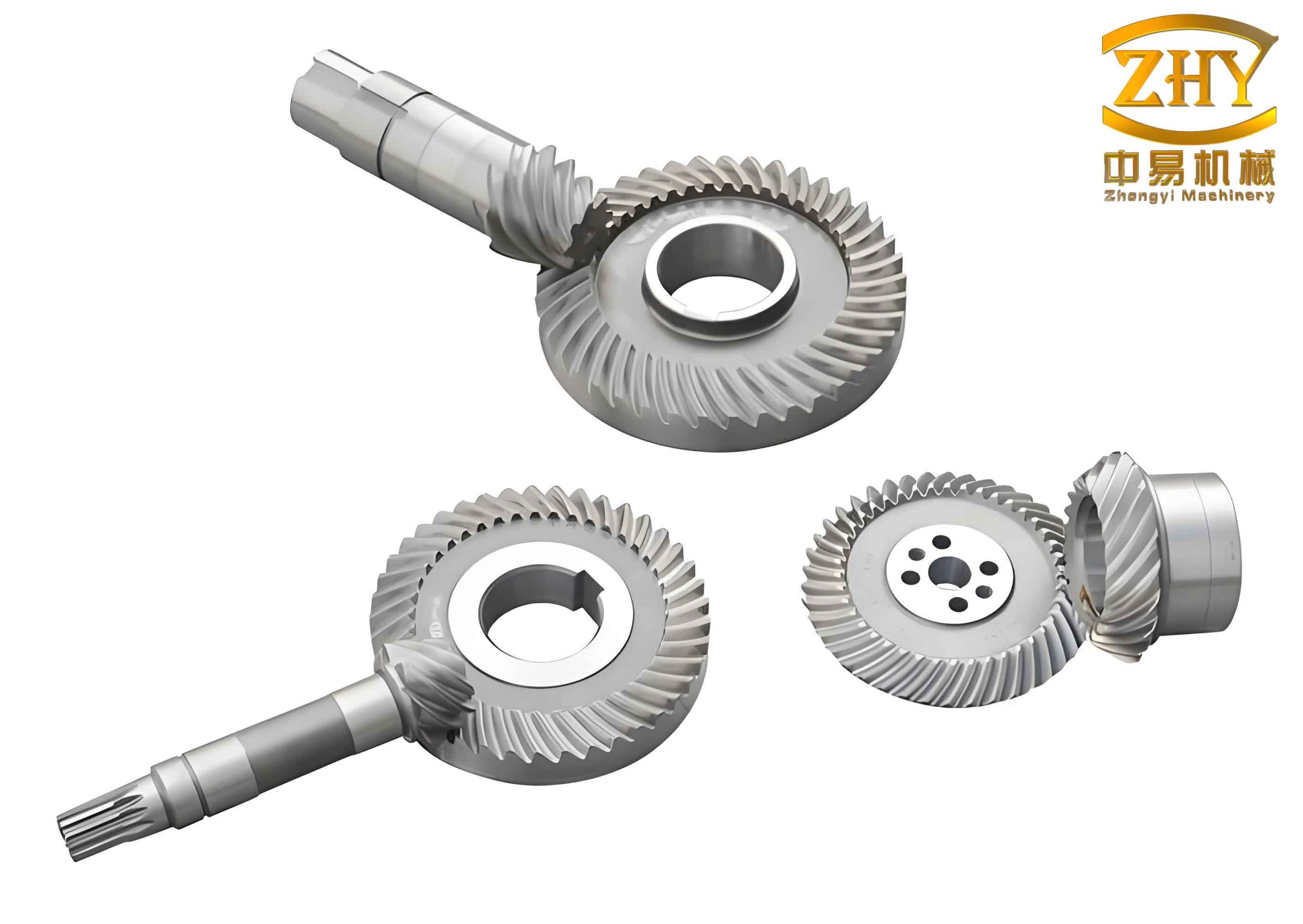
In the field of gear transmission systems, hyperboloidal gears, often referred to as hypoid gears, play a critical role in applications requiring high torque and smooth motion transfer between non-intersecting axes. As an engineer specializing in computational mechanics, I have focused on investigating the meshing contact impact behavior of these gears using advanced finite element methods. This analysis is essential for improving gear design, durability, and performance, particularly under dynamic loading conditions. In this article, I present a comprehensive study on the finite element simulation of meshing contact impact in hyperboloidal gears, emphasizing virtual machining, model reconstruction, and explicit dynamic analysis. The goal is to provide insights into transient phenomena such as contact pressure distribution, stress fluctuations, and impact forces, which are often overlooked in static analyses. Throughout this work, the term “hyperboloidal gears” will be used repeatedly to underscore the specific gear type under investigation, highlighting their unique geometry and mechanical behavior.
The complexity of hyperboloidal gears stems from their curved tooth surfaces, which are generated through specialized machining processes like the Formate or HFT methods. Traditional analytical approaches struggle to capture the nonlinear contact dynamics during meshing, especially at the onset of motion where impact effects are pronounced. To address this, I employed a combined approach of virtual machining and finite element analysis (FEA), leveraging software tools like CATIA for geometric modeling and ABAQUS for explicit dynamic simulations. This methodology allows for a detailed exploration of how hyperboloidal gears behave under transient conditions, revealing phenomena that can inform better design practices. For instance, the initial impact phase, where gears transition from rest to steady-state meshing, can induce stress concentrations and force peaks that may lead to premature failure if not properly accounted for. By simulating this process, I aim to quantify these effects and contribute to the optimization of hyperboloidal gear systems.
To begin, I developed an accurate geometric model of a hyperboloidal gear pair. The gears were designed based on standard parameters, with a pinion and gear having 7 and 39 teeth, respectively. The virtual machining process was implemented using VB6.0 to control CATIA V5 through secondary development, simulating the CNC machining of hyperboloidal gears. This involved generating tooth surfaces via the HFT method for the gear and the Formate method for the pinion, ensuring precise geometry that reflects real-world manufacturing. The surface points were then reconstructed using NURBS (Non-Uniform Rational B-Spline) functions to create a smooth, continuous representation suitable for finite element meshing. The geometric parameters are summarized in Table 1, which provides key dimensions for the hyperboloidal gear pair. This table illustrates the intricate specifications required for hyperboloidal gears, including spiral angles, cone distances, and other critical metrics that influence their meshing behavior.
| Parameter | Pinion | Gear |
|---|---|---|
| Number of Teeth | 7 | 39 |
| Face Width (mm) | 68.34 | 63.00 |
| Outer Cone Distance (mm) | 214.37 | 222.51 |
| Spiral Angle (°) | 45.00 | 34.417 |
| Pitch Cone Angle (°) | 12.50 | 77.283 |
| Hand of Spiral | Left | Right |
The machining parameters for both the gear and pinion were derived using the “local conjugation principle,” which minimizes sensitivity to installation errors. For the gear, a Gleason No. 609 cutter was used with specific settings such as cutter diameter and blade angles, while for the pinion, a Gleason No. 116 cutter was applied with distinct configurations for concave and convex surfaces. These parameters are detailed in Table 2 and Table 3, highlighting the precision required in manufacturing hyperboloidal gears. The use of NURBS reconstruction ensured that the geometric model retained high accuracy, which is crucial for subsequent finite element analysis. The reconstructed surfaces were exported as CAD models, forming the basis for mesh generation. This step is vital because the quality of the finite element mesh directly affects the simulation results, particularly for contact problems where stress gradients are steep.
| Parameter | Value |
|---|---|
| Cutter Nominal Diameter (mm) | 304.8 |
| Outer Blade Pressure Angle (°) | 22.50 |
| Inner Blade Pressure Angle (°) | 22.50 |
| Blade Tip Radius (mm) | 2.41 |
| Machine Root Cone Angle (°) | 74.317 |
| Horizontal Wheel Position (mm) | -1.75 |
| Parameter | Concave Side (Outer Blade) | Convex Side (Inner Blade) |
|---|---|---|
| Cutter Tip Diameter (mm) | 285.43 | 329.79 |
| Blade Pressure Angle (°) | 20.00 | 25.00 |
| Blade Tip Radius (mm) | 2.97 | 2.97 |
| Machine Root Cone Angle (°) | -2.00 | -4.00 |
| Horizontal Wheel Position (mm) | -6.53 | 8.05 |
After obtaining the geometric model, I proceeded to construct the finite element model. Meshing was performed in Hypermesh software, where I utilized hexahedral linear reduced-integration elements (C3D8R) to discretize the hyperboloidal gears. These elements are well-suited for contact analyses due to their ability to handle large deformations and nonlinearities. The mesh density was carefully refined to ensure accuracy, with a focus on the tooth contact regions where stress concentrations are expected. The material properties were assigned as follows: elastic modulus of 210 GPa, Poisson’s ratio of 0.3, and density of 7800 kg/m³, typical for steel gears. To validate the mesh quality, I monitored the ratio of artificial strain energy to internal energy (ALLAE/ALLIE), keeping it below 1% to control hourglass effects, which can compromise results in explicit dynamics. This meticulous setup is essential for reliable simulations of hyperboloidal gears, as their complex geometry demands high-fidelity meshing.
The boundary conditions and constraints were defined to mimic real-world operating conditions. Reference points were created on the axes of both the pinion and gear, coupled to their inner surfaces using kinematic coupling constraints. This allowed forces and moments to be transferred equivalently while permitting relative deformation under load. The reference points were constrained in all degrees of freedom except rotation about the gear axis. For the contact interactions, I defined five contact pairs between the pinion and gear teeth, incorporating a tangential friction coefficient of 0.15 to account for sliding effects. The pinion was driven at a rotational speed of 500 RPM, and the gear was subjected to a resisting torque of 9 × 10³ N·m. These settings simulate a typical power transmission scenario for hyperboloidal gears, enabling the analysis of dynamic meshing behavior from startup to steady-state.
For the simulation, I employed ABAQUS/Explicit, which uses an explicit central difference method combined with a penalty function approach for contact resolution. This solver is ideal for transient dynamic problems like meshing impact, as it avoids matrix inversion and handles nonlinearities efficiently. The governing equations of motion in explicit dynamics are discretized in time, with the acceleration calculated at each step. The contact force $F_c$ between gear teeth can be expressed using the penalty method as:
$$ F_c = k \cdot \delta $$
where $k$ is the penalty stiffness and $\delta$ is the penetration distance. For hyperboloidal gears, the contact area is elliptical due to the curvature of the tooth surfaces, and the contact pressure distribution follows Hertzian theory in a simplified form. The maximum contact pressure $p_{\text{max}}$ for an elliptical contact patch is given by:
$$ p_{\text{max}} = \frac{3F}{2\pi a b} $$
where $F$ is the normal load, and $a$ and $b$ are the semi-major and semi-minor axes of the contact ellipse, respectively. However, in dynamic meshing, these parameters vary with time, necessitating a transient analysis. The explicit solver computes these variations incrementally, capturing the impact phenomena during gear engagement.
The simulation results reveal several key insights into the meshing contact impact of hyperboloidal gears. Initially, upon engagement, the contact force exhibits a sharp peak, reaching approximately twice the steady-state value. This impact phase is critical, as it induces high stresses that may affect gear longevity. The contact pressure distribution on the tooth surfaces was visualized, showing elliptical contact patches that migrate along the contact path during meshing. This migration implies that each point on the tooth surface undergoes cyclic loading, which can lead to contact fatigue over time. For instance, on the gear’s convex side and the pinion’s concave side, the contact pressure peaks in the center of the ellipse and decays outward, consistent with theoretical expectations. The von Mises stress distribution further indicates that high stresses extend beyond the immediate contact area, spreading toward the tooth root and tip, highlighting the importance of considering full-tooth stress fields in design.
To quantify the impact behavior, I analyzed the time history of the resultant contact force. As shown in Figure 1 (represented conceptually here), the force rapidly ascends to around 80 kN at the onset of meshing, then oscillates before stabilizing near 40 kN. This demonstrates that the initial impact force can be nearly double the steady-state force, underscoring the need for designs that accommodate such transients. The fluctuation frequency correlates with the gear’s rotational speed and tooth engagement frequency. For a hyperboloidal gear pair with a pinion speed of 500 RPM and 7 teeth, the tooth engagement frequency $f_e$ can be calculated as:
$$ f_e = \frac{N \cdot \omega}{60} $$
where $N$ is the number of pinion teeth (7) and $\omega$ is the rotational speed in RPM (500). Thus, $f_e = \frac{7 \times 500}{60} \approx 58.33 \text{ Hz}$. This frequency manifests in the contact force oscillations, particularly during the impact phase.
Moreover, I examined the contact forces for individual tooth pairs during sequential engagement. The first tooth pair to enter meshing experiences the most severe impact, with force peaks around 80 kN and high-frequency fluctuations. Subsequent tooth pairs show progressively smoother force profiles, with the second pair stabilizing faster and the third pair nearly devoid of impact effects. This pattern suggests that the initial impact is localized to the first engaging pair, after which the system dampens out transient vibrations. Similarly, the bending stress at the tooth root for the first pair exhibits sharp spikes, though the peak magnitude remains comparable to steady-state values. This indicates that while impact increases stress fluctuations, it may not drastically elevate the maximum stress, but the cyclic nature could accelerate fatigue crack initiation. The bending stress $\sigma_b$ at the tooth root can be estimated using the Lewis formula modified for hyperboloidal gears:
$$ \sigma_b = \frac{F_t \cdot K_a \cdot K_m}{b \cdot m_n \cdot Y} $$
where $F_t$ is the tangential force, $K_a$ is the application factor, $K_m$ is the load distribution factor, $b$ is the face width, $m_n$ is the normal module, and $Y$ is the Lewis form factor. In dynamic conditions, $F_t$ varies with time, leading to transient stress values.
To further elaborate on the results, I present Table 4, which summarizes the key simulation outcomes for the hyperboloidal gear pair. This table encapsulates metrics such as maximum contact force, steady-state force, contact pressure range, and stress values, providing a concise overview of the impact behavior. The data underscores the significance of transient effects in hyperboloidal gears, which are often designed based on static load assumptions.
| Metric | Value | Description |
|---|---|---|
| Maximum Transient Contact Force | 80 kN | Peak force during initial impact |
| Steady-State Contact Force | 40 kN | Average force after stabilization |
| Contact Pressure Range | 0.5 – 1.2 GPa | Variation across contact ellipse |
| Maximum von Mises Stress | 650 MPa | Peak stress in tooth root region |
| Impact Duration | ~0.005 s | Time for force to stabilize |
| Tooth Engagement Frequency | 58.33 Hz | Frequency of tooth pair contact |
The migration of the contact ellipse along the tooth surface is another critical aspect. During a full meshing cycle, the contact patch moves from the toe to the heel of the gear tooth, causing each point to experience periodic loading and unloading. This movement can be described parametrically using the gear rotation angle $\theta$. The contact path coordinates $(x, y)$ on the tooth surface might follow a curve defined by the gear geometry, such as a spherical involute. For hyperboloidal gears, the surface equation in parametric form can be expressed as:
$$ \mathbf{S}(u,v) = \sum_{i=0}^{n} \sum_{j=0}^{m} R_{ij} N_{i,p}(u) N_{j,q}(v) \mathbf{P}_{ij} $$
where $\mathbf{S}(u,v)$ is the NURBS surface, $R_{ij}$ are rational basis functions, $N_{i,p}$ and $N_{j,q}$ are B-spline basis functions of degrees $p$ and $q$, and $\mathbf{P}_{ij}$ are control points. This representation allows for precise tracking of contact points during simulation. The periodic stress variation at any point $\mathbf{P}$ on the tooth surface can be modeled as a function of time $t$:
$$ \sigma(\mathbf{P}, t) = \sigma_0 + \Delta \sigma \sin(2\pi f_e t + \phi) $$
where $\sigma_0$ is the mean stress, $\Delta \sigma$ is the stress amplitude, and $\phi$ is a phase shift. This cyclic loading is a primary driver of contact fatigue in hyperboloidal gears, necessitating materials with high endurance limits.
In terms of computational methodology, the explicit dynamic analysis required careful time step selection to ensure stability. The critical time step $\Delta t_c$ for explicit integration is governed by the Courant condition:
$$ \Delta t_c \leq \frac{L_{\text{min}}}{c} $$
where $L_{\text{min}}$ is the smallest element dimension and $c$ is the speed of sound in the material, given by $c = \sqrt{E/\rho}$ for elastic waves. For steel, $c \approx 5000 \text{ m/s}$, and with element sizes around 0.5 mm, $\Delta t_c$ is on the order of 0.1 microseconds. The simulation used an automatic time stepping scheme in ABAQUS/Explicit to maintain stability while capturing transient details. This approach ensured that the impact phenomena in hyperboloidal gears were resolved accurately, without numerical artifacts.
The findings from this simulation have important implications for the design and application of hyperboloidal gears. First, the doubling of contact force during impact suggests that safety factors should be adjusted to account for transient overloads. Designers might consider using softer materials or introducing micro-geometry modifications, such as tip relief or crowning, to mitigate impact effects. Second, the localized stress fluctuations in the first engaging tooth pair indicate that load sharing among multiple tooth pairs is not immediate; thus, improving the lead and profile modifications could enhance load distribution. Third, the cyclic nature of contact pressure underscores the need for advanced surface treatments, like carburizing or shot peening, to increase fatigue resistance in hyperboloidal gears.
To further explore the dynamics, I derived a simplified mathematical model for the meshing impact of hyperboloidal gears. The system can be represented as a two-degree-of-freedom oscillator with contact stiffness $k_c$ and damping $c_c$. The equations of motion for the pinion and gear are:
$$ I_p \ddot{\theta}_p + c_c (\dot{\theta}_p – \dot{\theta}_g) + k_c (\theta_p – \theta_g) = T_p $$
$$ I_g \ddot{\theta}_g + c_c (\dot{\theta}_g – \dot{\theta}_p) + k_c (\theta_g – \theta_p) = -T_g $$
where $I_p$ and $I_g$ are moments of inertia, $\theta_p$ and $\theta_g$ are angular displacements, $T_p$ is the driving torque, and $T_g$ is the load torque. The contact stiffness $k_c$ varies with tooth position, reflecting the changing geometry of hyperboloidal gears. Solving these equations numerically can provide additional insights into vibration modes and impact severity. However, the finite element approach offers greater fidelity by incorporating full geometry and nonlinear contact.
In conclusion, this study demonstrates the value of finite element simulation in analyzing the meshing contact impact of hyperboloidal gears. Through virtual machining and explicit dynamic analysis, I captured transient phenomena such as force peaks, stress fluctuations, and contact pressure migration. The results show that the initial impact force can reach twice the steady-state value, primarily affecting the first engaging tooth pair. These insights highlight the importance of considering dynamic effects in the design and optimization of hyperboloidal gears, which are widely used in automotive, aerospace, and industrial applications. Future work could extend this analysis to include thermal effects, lubrication, or manufacturing errors, further enhancing the understanding of hyperboloidal gear performance. By repeatedly emphasizing hyperboloidal gears throughout this article, I aim to reinforce their significance in mechanical transmission systems and encourage continued research into their dynamic behavior.
To summarize key formulas and data, I provide Table 5, which lists essential equations used in the analysis of hyperboloidal gears. This table serves as a quick reference for engineers interested in applying similar methodologies. Additionally, the integration of virtual machining with FEA proves to be a powerful tool for advancing gear technology, particularly for complex types like hyperboloidal gears where traditional methods fall short.
| Equation | Description | Application |
|---|---|---|
| $$ F_c = k \cdot \delta $$ | Penalty-based contact force | Dynamic contact resolution |
| $$ p_{\text{max}} = \frac{3F}{2\pi a b} $$ | Maximum Hertzian contact pressure | Contact stress estimation |
| $$ f_e = \frac{N \cdot \omega}{60} $$ | Tooth engagement frequency | Vibration analysis |
| $$ \sigma_b = \frac{F_t \cdot K_a \cdot K_m}{b \cdot m_n \cdot Y} $$ | Bending stress at tooth root | Strength design |
| $$ \Delta t_c \leq \frac{L_{\text{min}}}{c} $$ | Critical time step for explicit analysis | Simulation stability |
| $$ \mathbf{S}(u,v) = \sum_{i=0}^{n} \sum_{j=0}^{m} R_{ij} N_{i,p}(u) N_{j,q}(v) \mathbf{P}_{ij} $$ | NURBS surface representation | Geometric modeling |
Ultimately, the behavior of hyperboloidal gears under meshing impact is a multifaceted problem that requires a combination of advanced modeling techniques. This article contributes to the field by providing a detailed framework for simulation and analysis, paving the way for more robust and efficient hyperboloidal gear designs. As technology evolves, continued exploration of these dynamics will be crucial for meeting the demands of high-performance transmission systems.