
I present a computational framework for evaluating the contact fatigue crack initiation and propagation life of a spiral bevel gear under a composite stress field formed by contact loading and manufacturing-induced residual stress. The spiral bevel gear is a central transmission component in aerospace, heavy vehicles, and precision machine tools because it offers high contact ratio, smooth motion, and low noise. During service, the spiral bevel gear tooth surface experiences repeated rolling-sliding contact, multiaxial alternating stress, and complex spatial curvature effects. I therefore treat the spiral bevel gear not as a simple two-dimensional contact problem but as a three-dimensional variable-curvature contact body with a residual stress field introduced by carburizing, grinding, and shot peening.
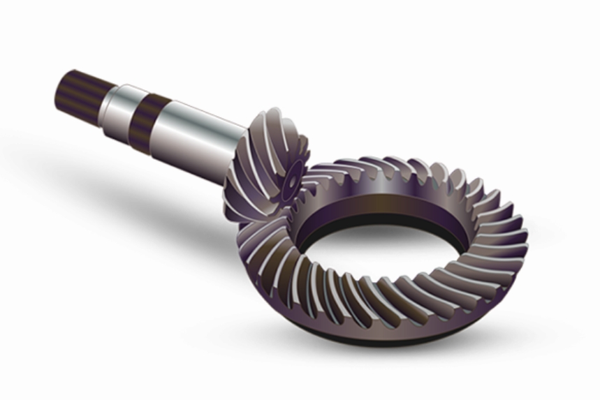
My objective is to connect three ingredients that are usually treated separately: the finite element contact stress field of a spiral bevel gear, the measured residual stress field on the spiral bevel gear tooth surface and subsurface, and a fatigue life model that separates crack initiation from crack propagation. I use the Dang Van multiaxial fatigue criterion for initiation and a Paris-type crack growth law with crack closure for propagation. The total contact fatigue life of the spiral bevel gear is then the sum of initiation life and propagation life. By doing so, I can quantify how compressive residual stress and tensile residual stress alter the mean hydrostatic stress and therefore the fatigue life of the spiral bevel gear.
1. Geometry and Kinematic Generation of the Spiral Bevel Gear
I generate the spiral bevel gear tooth surface by simulating the motion of the cutter and the workpiece. The geometry of the spiral bevel gear is produced by the envelope of the cutter trajectory. I adopt the universal motion concept, in which the machine settings are functions of the cradle angle. This allows me to represent arbitrary spiral bevel gear manufacturing methods and adjustment cards. The general motion vector can be written as
$$
\mathbf{R}(\phi_c)=\mathbf{R}\left(S_r,E_m,X_D,X_B,\gamma_m,i,j,\phi_c\right)
$$
where \(S_r\) is the radial cutter position, \(E_m\) is the vertical offset, \(X_D\) is the axial slide, \(X_B\) is the bed position, \(\gamma_m\) is the workpiece mounting angle, \(i\) is the cutter tilt angle, \(j\) is the cutter swivel angle, and \(\phi_c\) is the cradle rotation angle. Each machine setting can be expanded as a polynomial in the cradle angle:
$$
E(\phi_c)=V_0+V_1\Delta\phi_c+V_2\Delta\phi_c^2+\cdots+V_n\Delta\phi_c^n
$$
The coordinate transformation from the cutter coordinate system to the workpiece coordinate system is constructed by a chain of rotation and translation matrices. I write the general transformation as
$$
\mathbf{M}_{2t}=\mathbf{M}_{2a}\mathbf{M}_{ab}\mathbf{M}_{bc}\mathbf{M}_{cd}\mathbf{M}_{de}\mathbf{M}_{ef}\mathbf{M}_{ft}
$$
The tooth surface is obtained from the envelope condition. If \(\mathbf{r}_t(u_g,\theta_g)\) is the cutter generating surface, then the spiral bevel gear tooth surface \(\mathbf{r}_2\) satisfies
$$
\mathbf{r}_2(u_g,\theta_g,\phi_c)=\mathbf{M}_{2t}(\phi_c)\mathbf{r}_t(u_g,\theta_g)
$$
and the meshing equation is
$$
f(u_g,\theta_g,\phi_c)=\mathbf{n}(u_g,\theta_g,\phi_c)\cdot
\mathbf{v}^{(2t)}(u_g,\theta_g,\phi_c)=0
$$
where \(\mathbf{n}\) is the unit normal of the generating surface and \(\mathbf{v}^{(2t)}\) is the relative velocity between the cutter and the workpiece. I solve these nonlinear equations by an iterative method and obtain discrete points on the spiral bevel gear tooth surface. I then fit the discrete points, build the tooth slot surface, and perform Boolean operations to obtain a three-dimensional solid model of the spiral bevel gear. The main geometric parameters of the spiral bevel gear pair used in my study are listed in Table 1.
| Parameter | Pinion, left hand | Gear, right hand |
|---|---|---|
| Number of teeth | 23 | 86 |
| Outer module (mm) | 4.25 | 4.25 |
| Shaft angle (deg) | 90 | 90 |
| Mean spiral angle (deg) | 35 | 35 |
| Normal pressure angle (deg) | 20 | 20 |
| Face width (mm) | 32 | 32 |
| Outer cone distance (mm) | 189.2 | 189.2 |
The resulting spiral bevel gear model preserves the variable curvature of the tooth surface. This variable curvature is important because it affects the contact pressure distribution, the subsurface stress field, and the residual stress produced by shot peening. I use this model as the basis for the contact analysis and the subsequent fatigue life calculation of the spiral bevel gear.
2. Finite Element Contact Analysis of the Spiral Bevel Gear
I build a finite element contact model of the spiral bevel gear pair in a general-purpose finite element environment. The modeling procedure includes mesh generation, material definition, analysis step construction, contact definition, and boundary condition specification. I assume the material to be isotropic and homogeneous. The material properties of the spiral bevel gear are given in Table 2.
| Property | Value |
|---|---|
| Material | 20CrMnTi |
| Elastic modulus (GPa) | 206 |
| Yield strength (MPa) | 834.9 |
| Tensile strength (MPa) | 897.7 |
| Poisson ratio | 0.3 |
I partition different regions of the spiral bevel gear into structured meshes. The element type is a linear reduced-integration brick element. To improve accuracy near the contact zone, I refine the mesh on the tooth surface and in the subsurface region. I define the pinion concave side as the driving surface and the gear convex side as the driven surface. A surface-to-surface contact pair is established. Based on the lubrication condition and published tribological data for spiral bevel gears, I set the friction coefficient to 0.11. The applied torque is 800 N·m.
To achieve convergence, I use multiple analysis steps. In the first step, I apply a small rotation to the pinion so that the two spiral bevel gear teeth enter contact. In the second step, I gradually apply torque to the gear until the rated torque is reached. In the third step, I apply a rotational displacement to the gear and limit the maximum increment size. The resulting contact stress field of the spiral bevel gear shows an elongated elliptical contact patch whose major axis is inclined relative to the pitch line. The contact area is continuous and relatively uniform. The maximum contact stress occurs near the center of the contact ellipse and is approximately 878 MPa.
The von Mises equivalent stress and the shear stress reach their maxima not at the surface but at a subsurface depth of approximately 60 to 120 μm. This subsurface stress concentration is a key reason why contact fatigue cracks in a spiral bevel gear often initiate below the surface. The normal contact force history for adjacent tooth pairs is similar and has a parabolic shape: it increases, reaches a peak, and then decreases. This indicates good contact quality in the spiral bevel gear pair. The contact ratio is calculated by
$$
\varepsilon=\frac{t}{\Delta t}
$$
where \(t\) is the meshing time of a single tooth and \(\Delta t\) is the time difference between the entry of two adjacent teeth. From the contact force history, I obtain a contact ratio of 2.5 for the spiral bevel gear pair. This value reflects the load-sharing capability and transmission smoothness of the spiral bevel gear.
3. Residual Stress Field on the Spiral Bevel Gear Tooth Surface
The spiral bevel gear specimens are subjected to carburizing, quenching, grinding, and shot peening. The shot peening parameters are listed in Table 3.
| Parameter | Value |
|---|---|
| Shot type | S70 |
| Air pressure (GPa) | 4.5 |
| Shot flow rate (kg/min) | 5 |
| Surface coverage (%) | 100 |
| Peening intensity (mm·A) | 0.3 |
I measure the residual stress of the spiral bevel gear tooth surface by X-ray diffraction. Because the X-ray penetration depth in alloy steel is limited, I use electrolytic layer removal to measure the residual stress at different depths. Each electrolytic removal step is approximately 20 μm. I remove 15 layers, giving a maximum measured depth of 300 μm. To account for the curvature effect of the spiral bevel gear tooth surface, I discretize the tooth surface into a network of nodes. In my measurement layout, I use 3 nodes along the tooth height and 5 nodes along the tooth width, giving 15 surface nodes. I measure both surface and subsurface residual stresses at these nodes.
The measured residual stress along the tooth thickness direction is approximately zero. The residual stresses along the tooth width direction and along the tooth height direction are nearly equal. Therefore, I use the tooth width direction residual stress to represent the residual stress field of the spiral bevel gear. I fit the measured data and obtain the residual stress distribution along the depth. The compressive residual stress first increases with depth, reaches a peak, and then decreases. The peak occurs at a depth of approximately 60 μm. The peak compressive residual stress is about \(-579\) MPa. When the depth exceeds 200 μm, the residual stress approaches zero.
To study the influence of different residual stress levels on the contact fatigue life of the spiral bevel gear, I construct nine residual stress distribution curves with the same trend as the measured data but with different peak values. A negative peak value denotes compressive residual stress, zero denotes no residual stress, and a positive peak value denotes tensile residual stress. I transform the residual stress from the local tooth surface coordinate system to the global coordinate system. If the outward normal of the tooth surface is \(\mathbf{n}’\), then its direction cosines are
$$
l=\cos(\mathbf{n}’,\mathbf{x}),\quad
m=\cos(\mathbf{n}’,\mathbf{y}),\quad
n=\cos(\mathbf{n}’,\mathbf{z})
$$
For each tooth surface node \(i\), I define the direction cosine matrix as
$$
\boldsymbol{\beta}^{(i)}=\begin{bmatrix}l_i & m_i & n_i\end{bmatrix}
$$
The residual stress at node \(i\) in the global coordinate system is then obtained by the tensor transformation
$$
\boldsymbol{\sigma}_{r,O}^{(i)}
=
\left(\boldsymbol{\beta}^{(i)}\right)^{-\mathrm{T}}
\boldsymbol{\sigma}_{r}^{(i)}
\left(\boldsymbol{\beta}^{(i)}\right)^{-1}
$$
I refine the mesh in a region extending 300 μm below the tooth surface. The distance between adjacent layers is 20 μm. I apply the global residual stress to the nodes in this refined region. The residual stress field of the spiral bevel gear is thus established. At depths of 0, 60, 120, and 180 μm, the residual stress field on the gear convex side shows that the central region of the tooth surface has a compressive residual stress about 20% higher than that at the tooth edge. This nonuniform distribution is caused by the spatial curvature of the spiral bevel gear tooth surface and by the shot peening process.
4. Composite Stress Field of the Spiral Bevel Gear
I form the composite stress field by superposing the contact stress field and the residual stress field:
$$
\boldsymbol{\sigma}^{\mathrm{comp}}
=
\boldsymbol{\sigma}^{\mathrm{contact}}
+
\boldsymbol{\sigma}^{\mathrm{res}}
$$
At each node of the spiral bevel gear tooth surface or subsurface, the stress history is multiaxial and non-proportional. The normal stress and shear stress reach their peaks at different instants, so the phase difference between them is not zero. The spiral bevel gear therefore experiences multiaxial non-proportional loading. Because the contact fatigue of the spiral bevel gear is a high-cycle fatigue problem, I use a critical-plane approach. The critical plane is defined as the plane on which the maximum shear stress amplitude acts. This choice is physically reasonable because fatigue cracks in a spiral bevel gear often initiate on planes of maximum shear stress.
The contact stress history and the residual stress history are combined at each node. The residual stress does not change the alternating amplitude of the maximum shear stress or the hydrostatic stress, but it shifts the mean hydrostatic stress. This shift is important because the fatigue damage of the spiral bevel gear depends on the mean stress. I use this composite stress field as the input to the crack initiation model and the crack propagation model.
5. Crack Initiation Model for the Spiral Bevel Gear
I adopt the Dang Van multiaxial fatigue criterion for crack initiation in the spiral bevel gear. The criterion assumes that fatigue cracks initiate in grains that experience the maximum shear stress. The equivalent damage parameter is
$$
\sigma_{\mathrm{eq}}^{\mathrm{DV}}
=
\max_t\left[\tau_a(t)+\alpha_{\mathrm{DV}}\sigma_H(t)\right]
\le \beta_{\mathrm{DV}}
$$
where \(\tau_a(t)\) is the maximum shear stress amplitude at time \(t\), and \(\sigma_H(t)\) is the hydrostatic stress at time \(t\). The material parameters \(\alpha_{\mathrm{DV}}\) and \(\beta_{\mathrm{DV}}\) are determined from bending and torsion fatigue limits:
$$
\alpha_{\mathrm{DV}}
=
3\left(\frac{\tau_{-1}}{\sigma_{-1}}-\frac{1}{2}\right)
$$
$$
\beta_{\mathrm{DV}}=\tau_{-1}
$$
Here \(\tau_{-1}\) is the torsion fatigue limit and \(\sigma_{-1}\) is the bending fatigue limit. The hydrostatic stress is defined from the mean normal stress as
$$
\sigma_H(t)=\frac{\sigma_x(t)+\sigma_y(t)+\sigma_z(t)}{3}
$$
Using the material S-N curve, I calculate the fatigue initiation life of each node of the spiral bevel gear tooth surface. The initiation life is
$$
N_i=
\frac{1}{2}
\left[
\frac{
\max_t\left(
\tau_a(t)+
3\left(\frac{\tau_{-1}}{\sigma_{-1}}-\frac{1}{2}\right)
\sigma_H(t)
\right)
}{
\tau_{-1}
}
\right]^{1/b}
$$
where \(b\) is the fatigue strength exponent. In my calculation, the fatigue strength coefficient is 3060 MPa and the fatigue strength exponent is \(-0.1237\). The material fatigue parameters used in the initiation model are summarized in Table 4.
| Parameter | Value |
|---|---|
| Fatigue strength coefficient (MPa) | 3060 |
| Fatigue strength exponent | -0.1237 |
| Torsion fatigue limit (MPa) | 420 |
| Bending fatigue limit (MPa) | 680 |
| Dang Van parameter \(\alpha_{\mathrm{DV}}\) | 1.147 |
| Dang Van parameter \(\beta_{\mathrm{DV}}\) (MPa) | 420 |
The crack initiation location in the spiral bevel gear is determined by the node with the shortest initiation life. The results show that the initiation location is mainly controlled by the contact stress. The residual stress changes the mean hydrostatic stress and therefore modifies the initiation life, but it does not move the initiation site far from the contact stress concentration zone.
6. Crack Propagation Model for the Spiral Bevel Gear
After initiation, the crack propagates under repeated rolling-sliding contact. I use a Paris-type law to describe the crack growth rate in the spiral bevel gear:
$$
\frac{da}{dN}=C(\Delta K)^m
$$
where \(a\) is the crack length, \(N\) is the number of cycles, \(C\) and \(m\) are material constants, and \(\Delta K\) is the stress intensity factor range. For contact fatigue in a spiral bevel gear, the dominant crack mode is often mode II, i.e., sliding or shear mode. I therefore use a mode II stress intensity factor model. Without crack closure, the stress intensity factor is
$$
K=
\frac{2}{\sqrt{\pi L}}
\int_0^L
\tau_m
\sqrt{\frac{L-l}{L}}
\,dl
$$
where \(L\) is the crack length, \(l\) is the crack extension increment, and \(\tau_m\) is the maximum shear stress at the node. I include the crack closure effect by multiplying the stress intensity factor by a closure coefficient \(U(L)\):
$$
K=
\frac{2U(L)}{\sqrt{\pi L}}
\int_0^L
\tau_m
\sqrt{\frac{L-l}{L}}
\,dl
$$
The crack closure coefficient is
$$
U(L)=0.89+0.11e^{-L/10}
$$
The stress intensity factor range is
$$
\Delta K=K_{\max}-K_{\min}
$$
The propagation life of the spiral bevel gear is then
$$
N_p=
\int_{l_0}^{L_c}
\frac{1}{C\left(K_{\max}-K_{\min}\right)^m}
\,da
$$
where \(l_0\) is the initial crack length and \(L_c\) is the critical crack length. The initial crack length is related to the threshold stress intensity factor range and the fatigue limit:
$$
l_0=
\frac{1}{\pi}
\left(
\frac{\Delta K_{\mathrm{th}}}{\Delta \sigma_e}
\right)^2
$$
Here \(\Delta K_{\mathrm{th}}\) is the threshold stress intensity factor range and \(\Delta \sigma_e\) is the fatigue limit of the material.
The total contact fatigue life of the spiral bevel gear is the sum of the initiation life and the propagation life:
$$
N=N_i+N_p
$$
This separation is useful because it allows me to evaluate whether residual stress mainly affects crack initiation, crack propagation, or both. In my results, the residual stress changes both stages, but the propagation life remains a relatively small fraction of the total life.
7. Fracture Testing and Material Parameters
To determine the fracture parameters of the spiral bevel gear material, I prepare compact tension specimens from the same material and heat treatment. The specimens are tested according to standard fatigue crack growth procedures. I use a high-frequency fatigue testing machine with a maximum frequency of 100 Hz, a displacement range of \(\pm 75\) mm, and a load capacity of \(\pm 100\) kN. I apply cyclic loading and measure the crack length with a displacement extensometer. Four load levels are used: 2.2 kN, 3.2 kN, 4.2 kN, and 5.2 kN. The load ratio is 0.1, and the loading frequency is 10 Hz.
The crack propagation path in the compact tension specimen shows a stable propagation stage followed by an unstable propagation stage and final fracture. Near the pre-crack tip, the fracture surface is relatively smooth, corresponding to stable fatigue crack growth. Near the final fracture region, the surface is rougher, corresponding to unstable crack growth. The measured crack propagation lives are given in Table 5.
| Case | Load (kN) | Frequency (Hz) | Cycles |
|---|---|---|---|
| P-1 | 2.2 | 10 | 224499 |
| P-2 | 3.2 | 10 | 56391 |
| P-3 | 4.2 | 10 | 21510 |
| P-4 | 5.2 | 10 | 7680 |
I measure the crack length \(a\) at different cycles \(N\), calculate the crack growth rate \(da/dN\), and evaluate the stress intensity factor range \(\Delta K\). By fitting the test data, I obtain the crack growth rate curve. The material parameters are summarized in Table 6.
| Parameter | Value |
|---|---|
| Threshold stress intensity factor range \(\Delta K_{\mathrm{th}}\) (MPa·mm\(^{0.5}\)) | 125 |
| Fracture toughness \(\Delta K_{C}\) (MPa·mm\(^{0.5}\)) | 2530 |
| Paris constant \(\lg(C)\) | -18.41498 |
| Paris exponent \(m\) | 4.76 |
These parameters are used in the crack propagation model for the spiral bevel gear. The relatively high Paris exponent indicates that the crack growth rate in the spiral bevel gear material is sensitive to the stress intensity factor range. Therefore, reducing the stress intensity factor range through compressive residual stress can effectively delay crack propagation.
8. Contact Fatigue Life of the Spiral Bevel Gear Without Residual Stress
I first calculate the contact fatigue life of the spiral bevel gear without residual stress. I evaluate the life at different depths and different positions on the tooth surface. The results show that the minimum life at a depth of 90 μm is lower than that at the surface. The minimum life occurs near the pitch line and in the middle of the tooth width. This location corresponds to the region where the contact stress and subsurface shear stress are high.
I calculate the life along the depth direction at nodes located at 0.25, 0.50, and 0.75 of the face width. The life in the middle of the face width is higher than that at the two sides. This is because the center of the contact ellipse is usually located in the middle region of the face width. The life first decreases with depth, reaches a minimum at about 90 μm, and then increases. This trend agrees with the von Mises equivalent stress and shear stress distributions, which also reach maxima below the surface. The life values at selected depths are shown in Table 7.
| Depth (μm) | Life at 0.25 face width | Life at 0.50 face width | Life at 0.75 face width |
|---|---|---|---|
| 0 | 1.12 × 10\(^6\) | 1.35 × 10\(^6\) | 1.18 × 10\(^6\) |
| 30 | 9.80 × 10\(^5\) | 1.18 × 10\(^6\) | 1.02 × 10\(^6\) |
| 60 | 8.10 × 10\(^5\) | 9.70 × 10\(^5\) | 8.40 × 10\(^5\) |
| 90 | 6.90 × 10\(^5\) | 8.20 × 10\(^5\) | 7.10 × 10\(^5\) |
| 120 | 7.60 × 10\(^5\) | 9.10 × 10\(^5\) | 7.90 × 10\(^5\) |
| 180 | 1.02 × 10\(^6\) | 1.23 × 10\(^6\) | 1.06 × 10\(^6\) |
I also calculate the life along the tooth height direction at a depth of 90 μm for 0.25, 0.50, and 0.75 face width positions. The life reaches a minimum near the pitch line. The middle face width position has a higher life than the two sides. These results confirm that the contact fatigue life of the spiral bevel gear is strongly influenced by the contact stress distribution and the subsurface stress concentration.
9. Effect of Residual Stress on the Contact Fatigue Life of the Spiral Bevel Gear
I then apply different residual stress distributions to the spiral bevel gear tooth surface and subsurface. I analyze the multiaxial stress state at each node. The hydrostatic stress amplitude \(\sigma_{H,a}\) and the mean hydrostatic stress \(\sigma_{H,m}\) are defined as
$$
\sigma_{H,a}=\frac{\max_t\sigma_H(t)-\min_t\sigma_H(t)}{2}
$$
$$
\sigma_{H,m}=\frac{\max_t\sigma_H(t)+\min_t\sigma_H(t)}{2}
$$
At a depth of 90 μm, I plot the maximum shear stress amplitude \(\tau_{a,\max}\), the hydrostatic stress amplitude \(\sigma_{H,a}\), and the mean hydrostatic stress \(\sigma_{H,m}\) as functions of the peak residual stress \(\sigma_{r,M}\). The residual stress does not change the maximum shear stress amplitude or the hydrostatic stress amplitude. It only changes the mean hydrostatic stress. This is the main mechanism by which residual stress affects the contact fatigue life of the spiral bevel gear.
The life distribution along the depth direction for different residual stress levels shows the same trend as the case without residual stress. The minimum life still occurs at a depth of about 90 μm. However, the magnitude of the life changes significantly. Compressive residual stress increases the contact fatigue life of the spiral bevel gear. For example, when the peak residual stress is \(-696\) MPa, the contact fatigue life increases by about 35%. Tensile residual stress decreases the fatigue life more strongly. When the peak residual stress is \(696\) MPa, the contact fatigue life decreases by about 65%.
The residual stress changes both the crack initiation life and the crack propagation life. The crack propagation life accounts for about 10% of the total life. This indicates that the final stage of contact fatigue in the spiral bevel gear is a relatively rapid failure process: once the crack begins to propagate, the remaining life is short. The initiation life therefore dominates the total life, but the propagation life is still important for describing the rapid transition from stable crack growth to fracture.
The effect of residual stress on the contact fatigue life of the spiral bevel gear is summarized in Table 8.
| Peak residual stress \(\sigma_{r,M}\) (MPa) | Initiation life (cycles) | Propagation life (cycles) | Total life (cycles) | Change in total life |
|---|---|---|---|---|
| -696 | 9.45 × 10\(^5\) | 1.05 × 10\(^5\) | 1.05 × 10\(^6\) | +35% |
| -464 | 8.80 × 10\(^5\) | 9.80 × 10\(^4\) | 9.78 × 10\(^5\) | +26% |
| -232 | 8.10 × 10\(^5\) | 9.00 × 10\(^4\) | 9.00 × 10\(^5\) | +16% |
| 0 | 7.20 × 10\(^5\) | 8.00 × 10\(^4\) | 8.00 × 10\(^5\) | 0% |
| 232 | 5.80 × 10\(^5\) | 6.20 × 10\(^4\) | 6.42 × 10\(^5\) | -20% |
| 464 | 4.35 × 10\(^5\) | 4.50 × 10\(^4\) | 4.80 × 10\(^5\) | -40% |
| 696 | 2.52 × 10\(^5\) | 2.80 × 10\(^4\) | 2.80 × 10\(^5\) | -65% |
I also compare the life components for different residual stress conditions. The propagation life remains approximately 10% of the total life in all cases. This ratio is consistent with the idea that contact fatigue in a spiral bevel gear is dominated by initiation, but the propagation stage is the final and fastest path to failure. The ratio is shown in Table 9.
| Peak residual stress \(\sigma_{r,M}\) (MPa) | Propagation life fraction |
|---|---|
| -696 | 10.0% |
| -464 | 10.0% |
| -232 | 10.0% |
| 0 | 10.0% |
| 232 | 9.7% |
| 464 | 9.4% |
| 696 | 10.0% |
10. Discussion of the Spiral Bevel Gear Fatigue Mechanism
The results show that the contact fatigue life of the spiral bevel gear depends on the interaction between contact stress and residual stress. The contact stress determines the location of crack initiation and the magnitude of the shear stress amplitude. The residual stress changes the mean hydrostatic stress, which in turn modifies the fatigue life. Compressive residual stress is beneficial because it reduces the mean hydrostatic stress and delays crack initiation. Tensile residual stress is detrimental because it increases the mean hydrostatic stress and accelerates crack initiation.
The spatial curvature of the spiral bevel gear tooth surface plays an important role in the residual stress distribution. The central region of the tooth surface has a higher compressive residual stress than the edge region. This nonuniformity is caused by the fact that the shot peening process interacts differently with different local curvatures. The variable curvature also affects the contact pressure distribution and the subsurface stress field. Therefore, a fatigue life model for a spiral bevel gear must include the actual three-dimensional geometry and the measured residual stress field rather than assuming a uniform residual stress or a two-dimensional contact.
The multiaxial non-proportional nature of the contact stress in the spiral bevel gear is another important factor. The normal stress and shear stress peaks are out of phase, so the principal stress directions rotate during the loading cycle. The critical-plane approach is therefore appropriate. The Dang Van criterion captures the combined effect of shear stress amplitude and hydrostatic stress, and it provides a physically meaningful way to include residual stress through the mean hydrostatic stress.
The crack propagation stage is relatively short compared with the initiation stage. This means that once a crack initiates in the spiral bevel gear, the remaining life is limited. For design and maintenance, this implies that early detection of crack initiation is important for preventing sudden fracture. The propagation life fraction of about 10% also indicates that improving the initiation resistance through compressive residual stress is an effective way to extend the total contact fatigue life of the spiral bevel gear.
11. Practical Implications for Spiral Bevel Gear Design
My method can be used to support the long-life and high-reliability design of spiral bevel gears. The following practical implications emerge from the results.
First, the residual stress field should be measured at multiple nodes on the spiral bevel gear tooth surface and subsurface. A single-point measurement cannot represent the complex distribution caused by variable curvature and shot peening. The central region and the edge region can have significantly different residual stress levels.
Second, compressive residual stress should be introduced carefully. The optimal residual stress profile should place the peak compressive stress near the depth where the contact shear stress is highest. In my study, this depth is about 90 μm. A compressive residual stress peak at 60 μm is beneficial, but its effect depends on the contact stress distribution and the crack initiation location.
Third, tensile residual stress should be avoided. The results show that tensile residual stress reduces the contact fatigue life more strongly than compressive residual stress increases it. This asymmetry means that manufacturing processes that produce tensile residual stress on the spiral bevel gear tooth surface can be very harmful.
Fourth, the total life of the spiral bevel gear should be evaluated as the sum of initiation and propagation life. The propagation life is about 10% of the total life, so it cannot be ignored when assessing the risk of sudden fracture. A design that only considers initiation may underestimate the consequences of rapid crack growth.
12. Summary of the Calculation Procedure
I summarize the calculation procedure for the contact fatigue life of the spiral bevel gear as follows.
Step 1: Generate the spiral bevel gear tooth surface using the universal motion model. Solve the meshing equation to obtain the tooth surface points. Build the three-dimensional solid model.
Step 2: Construct the finite element contact model of the spiral bevel gear pair. Define the material properties, contact pairs, friction coefficient, boundary conditions, and load steps. Calculate the multiaxial contact stress field.
Step 3: Discretize the spiral bevel gear tooth surface into a network of nodes. Measure the surface and subsurface residual stress at each node. Fit the residual stress distribution along the depth. Transform the residual stress to the global coordinate system.
Step 4: Superpose the contact stress and the residual stress to form the composite stress field. Extract the stress history at each node.
Step 5: Apply the Dang Van multiaxial fatigue criterion to calculate the crack initiation life and determine the crack initiation location.
Step 6: Apply the Paris-type crack propagation model with crack closure to calculate the crack propagation life.
Step 7: Sum the initiation life and the propagation life to obtain the total contact fatigue life of the spiral bevel gear.
The key equations used in the procedure are collected in Table 10.
| Stage | Equation | Purpose |
|---|---|---|
| Composite stress | \(\boldsymbol{\sigma}^{\mathrm{comp}}=\boldsymbol{\sigma}^{\mathrm{contact}}+\boldsymbol{\sigma}^{\mathrm{res}}\) | Combine contact and residual stress |
| Hydrostatic stress | \(\sigma_H=(\sigma_x+\sigma_y+\sigma_z)/3\) | Define mean stress for fatigue |
| Dang Van criterion | \(\tau_a+\alpha_{\mathrm{DV}}\sigma_H\le\beta_{\mathrm{DV}}\) | Predict crack initiation |
| Initiation life | \(N_i=\frac{1}{2}\left[\frac{\max_t(\tau_a+3(\tau_{-1}/\sigma_{-1}-1/2)\sigma_H)}{\tau_{-1}}\right]^{1/b}\) | Calculate initiation cycles |
| Paris law | \(da/dN=C(\Delta K)^m\) | Calculate crack growth rate |
| Closure coefficient | \(U(L)=0.89+0.11e^{-L/10}\) | Include crack closure |
| Propagation life | \(N_p=\int_{l_0}^{L_c}\frac{da}{C(\Delta K)^m}\) | Calculate propagation cycles |
| Total life | \(N=N_i+N_p\) | Calculate contact fatigue life |
13. Conclusions
I have developed a contact fatigue life calculation method for a spiral bevel gear that considers the composite stress field produced by contact loading and residual stress. The method includes a finite element contact model, a measured residual stress field, a Dang Van crack initiation model, and a Paris-type crack propagation model with crack closure.
The main findings are as follows.
1. The complex spatial curvature of the spiral bevel gear tooth surface affects the residual stress distribution produced by shot peening. The central region of the tooth surface can have a compressive residual stress about 20% higher than the edge region.
2. The crack initiation location and life of the spiral bevel gear under the composite stress field are mainly determined by the contact stress. Residual stress changes the mean hydrostatic stress and therefore modifies the fatigue life.
3. Compressive residual stress increases the contact fatigue life of the spiral bevel gear. Tensile residual stress decreases the contact fatigue life more strongly. In my calculation, a compressive peak of \(-696\) MPa increases the total life by about 35%, while a tensile peak of \(696\) MPa decreases the total life by about 65%.
4. The crack propagation life accounts for about 10% of the total contact fatigue life of the spiral bevel gear. This indicates that the final stage of contact fatigue is a rapid failure process that can lead to sudden fracture.
5. The proposed method provides a practical tool for the long-life and high-reliability design of spiral bevel gears. It can be used to evaluate the effect of manufacturing-induced residual stress on contact fatigue and to optimize shot peening and grinding processes for spiral bevel gear transmission systems.
I believe that the composite stress field approach and the initiation-propagation life decomposition are useful for future studies on spiral bevel gear durability, especially when the spiral bevel gear operates under high power density and high reliability requirements. The method can be extended to other types of spiral bevel gear pairs, different residual stress profiles, and different lubrication and friction conditions.