
In the realm of gear manufacturing, precision forming techniques for spur and pinion components have garnered significant attention due to their potential for enhancing mechanical properties and reducing material waste. As a researcher focused on advanced forming processes, I delve into the intricacies of metal flow during a novel two-step precision forming method for spur and pinion gears. This method, comprising a pre-forming stage to create a half-ridge slot geometry and a final splitting extrusion stage, aims to produce gears with清晰、饱满的轮齿及齿槽. The core of this investigation lies in elucidating the metal flow patterns through forward and backward point tracing using numerical simulations, which is crucial for optimizing the forming of spur and pinion gears in industrial applications. By analyzing displacement data and deformation mechanics, we can uncover the underlying principles that govern the success of this process for spur and pinion production.
The spur and pinion gears under consideration are characterized by a modulus of 4, 12 teeth, and a thickness of 30 mm. The two-step process begins with pre-forming, where a cylindrical billet is upset to form a radial undulating side with a half-ridge slot profile. This pre-formed geometry is essential for mitigating defects such as folding and塌角 in the final spur and pinion gear. The second step involves splitting extrusion, where the pre-formed part is forced through a die consisting of wedge-shaped elements arranged in a circular pattern. This stage induces continuous局部变形, facilitating the precise shaping of the teeth and roots. To simulate this, I employ Deform-3D software under conditions typical for hot forging of AISI-1045 steel, with a temperature of 1100°C for the workpiece and 200°C for the die, a friction coefficient of 0.3, and a tool velocity of 10 mm/s. The analysis focuses on a扇形区 representing half a tooth and half a tooth槽, allowing for efficient computation while capturing the symmetrical nature of spur and pinion gears.
During the pre-forming stage, the metal flow is predominantly characterized by global upsetting deformation. The cylindrical billet, with an initial diameter of 43 mm and height of 38.3 mm, undergoes radial expansion to form the half-ridge slot profile. Using forward point tracing, I placed 12 tracking points on the outer cylindrical surface of the billet, arranged in three columns (A, B, C) and four rows to monitor displacements in the axial (Z), tangential (Y), and radial (X) directions. The results indicate that all points experience outward radial movement, transforming the cylindrical surface into the undulating side of the pre-formed part. Notably, points in columns A and B remain approximately on their original meridional planes, while points in column C deviate increasingly from the基准面 from bottom to top, reflecting the influence of the die geometry. This pre-forming stage is critical for establishing the foundational shape that ensures successful final forming of spur and pinion gears. The axial displacements observed are relatively uniform, with the billet height decreasing as material flows radially. The table below summarizes the three-directional displacements for key tracking points during pre-forming, highlighting the overall镦粗 nature of this stage.
| Point Label | Z-displacement (mm) | Y-displacement (mm) | X-displacement (mm) |
|---|---|---|---|
| B1 | 0.00 | 0.00 | 0.00 |
| C1 | 0.00 | 1.43 | 0.30 |
| A1 | 0.00 | 2.30 | 0.62 |
| B2 | 1.62 | 0.53 | 0.00 |
| C2 | 2.12 | 2.63 | 0.94 |
| A2 | 2.27 | 3.35 | 0.91 |
| B3 | 3.40 | 1.07 | 0.00 |
| C3 | 3.92 | 3.65 | 1.21 |
| A3 | 4.16 | 4.37 | 1.17 |
| B4 | 5.62 | 1.50 | 0.01 |
| C4 | 5.22 | 4.45 | 1.33 |
| A4 | 5.07 | 5.24 | 1.40 |
The final forming stage, or splitting extrusion, is where the intricate metal flow for spur and pinion gears becomes evident. As the pre-formed part passes through the wedge die, continuous local deformation occurs within a limited circumferential radial width. The劈刃 initially splits the tooth root, and the inclined working surfaces exert tangential, radial, and axial forces on the material. This action pushes the metal in the tooth槽 space toward both sides, while the high radial resistance near the center forces material to flow outward to form the tooth tips. Axial displacements are pronounced due to the axial components of the forces, with tooth tips experiencing greater movement than roots. Forward tracing reveals that points on the ridge tops (e.g., A2-A4) and some on the lower端面 (B1, C1) are剥离 as excess material, which serves as a process compensation and removes decarburized layers. The remaining points show significant axial down-movement and tangential shifts, as detailed in the following table for the final forming stage displacements.
| Point Label | Z-displacement (mm) | Y-displacement (mm) | X-displacement (mm) |
|---|---|---|---|
| B1 | 剥离 | 剥离 | 剥离 |
| C1 | 剥离 | 剥离 | 剥离 |
| A1 | -0.03 | 0.32 | 1.22 |
| B2 | 6.80 | 0.00 | -3.34 |
| C2 | 7.10 | 2.00 | 3.16 |
| A2 | 剥离 | 剥离 | 剥离 |
| B3 | 5.80 | 0.86 | -3.59 |
| C3 | 5.85 | 1.89 | 2.28 |
| A3 | 剥离 | 剥离 | 剥离 |
| B4 | 0.68 | 1.80 | -3.68 |
| C4 | 1.00 | 1.34 | 1.14 |
| A4 | 剥离 | 剥离 | 剥离 |
To further elucidate the metal flow, backward point tracing was conducted from the final spur and pinion gear to the pre-formed part and billet. Points were selected on the addendum and dedendum meridional planes at various radial depths. The results indicate that material at the tooth tips originates from the侧表面 of the pre-formed ridges, confirming the lateral transfer observed in forward tracing. In contrast, material at the tooth roots derives from the non-surface regions of the billet, which is劈分 and pushed aside. The axial displacements are more significant for points near the surface, decreasing inward. This pattern underscores that deformation is concentrated in a peripheral zone, which is typical for连续局部成形 processes in spur and pinion gear manufacturing. The displacement data from backward tracing can be summarized using the following equations for average strain, though simplified for clarity: the volumetric strain is negligible due to incompressibility, expressed as $$ \nabla \cdot \mathbf{v} = 0 $$ where $\mathbf{v}$ is the velocity field. For the radial flow component, we can approximate the radial strain rate as $$ \dot{\varepsilon}_r = \frac{\partial v_r}{\partial r} $$ where $v_r$ is the radial velocity. In the context of spur and pinion forming, the effective strain $\bar{\varepsilon}$ can be estimated from displacement data using $$ \bar{\varepsilon} = \sqrt{\frac{2}{3} \varepsilon_{ij} \varepsilon_{ij}} $$ where $\varepsilon_{ij}$ are the components of the strain tensor. However, for practical purposes, the displacements tabulated above provide direct insight into the metal flow.
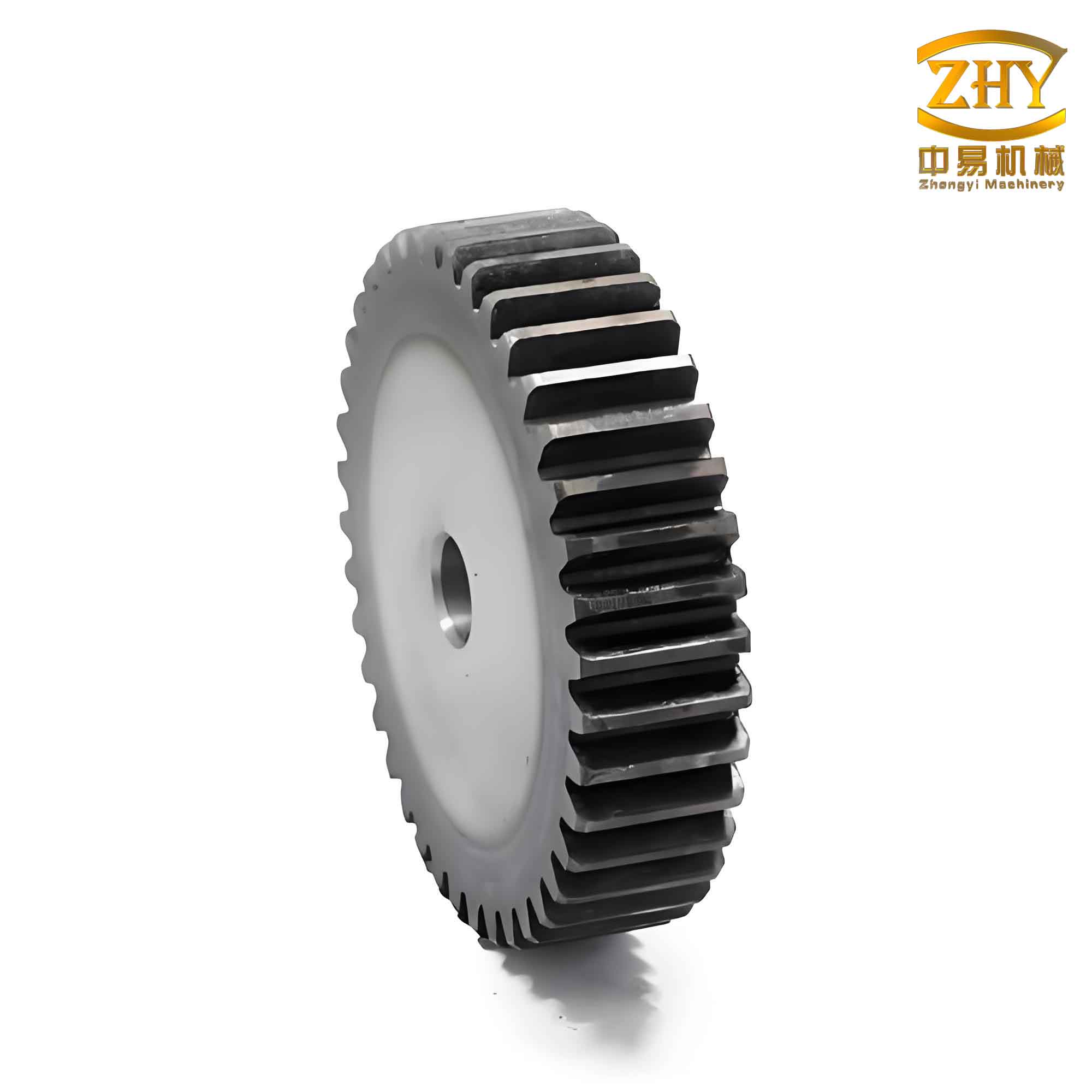
The metal flow patterns revealed through this analysis have profound implications for the precision forming of spur and pinion gears. In the pre-forming stage, the global upsetting ensures easy formation of the radial half-ridge slot profile, which is essential for distributing material evenly before final shaping. This step minimizes defects like folding, which are common in single-step forming of spur and pinion components. The预留 volume at the大端端面 compensates for potential塌角, demonstrating the process’s robustness. During splitting extrusion, the continuous local deformation allows for precise control over tooth geometry. The axial displacement, particularly the greater movement at tooth tips, ensures complete filling of the die corners, addressing a common issue in closed-die forging of spur and pinion gears. The剥离 of excess surface material as scrap not only provides a buffer for process variations but also eliminates decarburized layers, enhancing the surface quality of the final spur and pinion product. This two-step method, with its relatively simple die design and tooling actions, offers a viable alternative for producing high-quality spur and pinion gears with清晰、饱满的轮齿及齿槽.
From a mechanical perspective, the stress state during forming can be described using the yield criterion for plastic deformation. For many metals, the von Mises yield criterion is applicable: $$ \sigma_{\text{vm}} = \sqrt{\frac{1}{2}\left[(\sigma_1 – \sigma_2)^2 + (\sigma_2 – \sigma_3)^2 + (\sigma_3 – \sigma_1)^2\right]} = \sigma_y $$ where $\sigma_1, \sigma_2, \sigma_3$ are the principal stresses and $\sigma_y$ is the yield stress. In the splitting extrusion stage, the complex stress field—combining compressive radial stresses, shear tangential stresses, and tensile axial stresses—facilitates the desired metal flow for spur and pinion gears. The劈楔 geometry, with a劈分角 and劈刃倾角 of 60°, optimizes the force components to achieve this flow. The table below summarizes key parameters influencing the metal flow in spur and pinion gear forming, derived from the simulation and experimental insights.
| Parameter | Value | Role in Metal Flow |
|---|---|---|
| Modulus (m) | 4 mm | Determines tooth size and deformation scale |
| Number of Teeth (Z) | 12 | Affects circumferential distribution of flow |
| Billet Diameter (D0) | 43 mm | Initial radial dimension for upsetting |
| Pre-form Half-ridge Height | Variable | Guides radial flow during pre-forming |
| Splitting Angle | 60° | Influences tangential and radial force components |
| Wedge Inclination Angle | 60° | Controls axial flow and material剥离 |
| Friction Coefficient (μ) | 0.3 | Affects surface shear and axial displacement |
In conclusion, the two-step precision forming process for spur and pinion gears, involving半隆埂预成形 and劈挤终成形, exhibits distinct metal flow characteristics that contribute to its success. The pre-forming stage establishes a favorable geometry through global upsetting, while the final splitting extrusion induces continuous local deformation to shape the teeth and roots. Key findings include: the radial transfer of material from pre-formed ridges to tooth tips, the axial displacement that ensures die filling, and the剥离 of excess surface material for quality control. These insights, derived from detailed point tracing analysis, provide a foundation for optimizing the manufacturing of spur and pinion gears. Future work could explore the effects of varying parameters like temperature and die geometry on metal flow, further enhancing the efficiency and precision of this method for spur and pinion production. The integration of numerical simulation with physical experiments, as briefly mentioned, validates the reliability of this approach, making it a promising technique for industrial applications in spur and pinion gear fabrication.