
In my investigation of helicopter auxiliary power unit transmissions, the tapered pinion gear is one of the most heavily loaded and least forgiving components in the entire accessory drive train. The pinion gear transmits torque from the auxiliary power unit into the accessory gearbox while simultaneously locating several precision surfaces, including the gear journal, labyrinth seal, lock ring groove, rubber cup seat, and internal spline. Among these features, the internal spline is particularly sensitive to wear because it carries the full drive torque under boundary or mixed lubrication. In service, I repeatedly observed that the internal spline of the tapered pinion gear reaches its wear limit after only one or two overhaul intervals. This wear produces increased backlash, uneven contact, loss of torque transmission efficiency, and eventually gear failure. Because the pinion gear is a high-value, long-lead item, replacing the entire component is neither economically attractive nor logistically sustainable. My objective was therefore to develop a repair route that preserves the valuable tapered gear body and restores the worn internal spline through a controlled friction welding process.
The repair problem is not simply a dimensional restoration problem. The internal spline of the pinion gear must retain a hard, wear-resistant surface, while the weld joint must carry torsional and bending loads without cracking, unacceptable softening, or distortion. I therefore treated the repair as a coupled thermomechanical, metallurgical, and precision machining problem. The solution I selected uses continuous drive friction welding to replace the worn splined shaft diameter with a new, matching shaft section. This approach retains the original tapered pinion gear body, removes the worn spline, and creates a solid-state joint with a narrow heat-affected zone. The joint is then heat treated, precision machined, inspected, and assembled into the auxiliary power unit for bench validation.
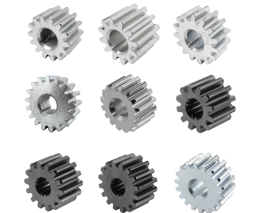
Service context and failure mechanism. The auxiliary power unit operates independently of the main engine. It supplies electrical power, compressed air, and starting torque before main engine operation. The tapered pinion gear is therefore part of a critical starting and ground-operation chain. When the pinion gear internal spline wears, the auxiliary power unit may still rotate, but the torque transfer becomes irregular. In severe cases, the spline teeth wear into a stepped or dished profile, and the mating shaft begins to rock within the spline. This rocking motion increases contact stress, accelerates wear, and can generate debris that contaminates the lubrication system. I found that the wear process follows a recognizable progression: initial asperity contact, micro-pitting, abrasive wear, plastic deformation, and finally loss of tooth profile. The wear rate is strongly dependent on contact pressure, sliding distance, lubrication condition, and surface hardness. A simplified Archard-type relationship is useful for describing the material loss:
$$ V_w = k_w \frac{F_n s}{H} $$
where \(V_w\) is the worn volume, \(k_w\) is a dimensionless wear coefficient, \(F_n\) is the normal contact force, \(s\) is the sliding distance, and \(H\) is the surface hardness. For the pinion gear internal spline, the normal force is proportional to the transmitted torque, while the sliding distance is associated with small oscillatory motions and tooth deflection under alternating load. Increasing the surface hardness after repair is therefore one of the most effective ways to extend the service life of the pinion gear.
The nominal contact pressure on the spline teeth can be estimated from the transmitted torque:
$$ p_c = \frac{2T}{N h l d_m} $$
where \(T\) is the torque, \(N\) is the number of spline teeth, \(h\) is the radial engagement height, \(l\) is the axial engagement length, and \(d_m\) is the mean spline diameter. When the pinion gear internal spline wears, \(h\) decreases and the load becomes concentrated on fewer teeth. The local pressure therefore rises, and the wear rate increases. This explains why the pinion gear spline often fails before the external gear teeth show comparable damage.
Repair strategy selection. I evaluated several candidate repair technologies before committing to friction welding. The criteria were heat input, joint strength, distortion risk, suitability for small precision parts, and ability to restore a hardened spline surface. Arc welding was rejected because the heat input is high, the heat-affected zone is wide, and the risk of distortion in a thin-walled pinion gear is unacceptable. Vacuum brazing was rejected because the joint strength depends strongly on the filler metal and is often only about 70% to 80% of the base material strength. Tungsten inert gas welding was also rejected because it is a fusion process that can produce gas porosity, inclusions, and an inhomogeneous weld zone. Continuous drive friction welding, by contrast, is a solid-state process that produces a narrow heat-affected zone, dense joint microstructure, and low residual stress. I had prior success with friction welding for replacing worn splined journals in other aviation transmission components, so I selected it as the core repair method for the pinion gear.
| Repair method | Heat input | Joint strength | Distortion risk | Suitability for pinion gear |
|---|---|---|---|---|
| Arc welding | High | Moderate | High | Not suitable |
| Vacuum brazing | Moderate | 70%–80% of base | Moderate | Not suitable |
| Tungsten inert gas welding | High | Moderate | High | Not suitable |
| Continuous drive friction welding | Low to moderate | Near or above base after heat treatment | Low | Suitable |
Key dimensional and performance requirements. The pinion gear repair must restore the internal spline and maintain all surrounding precision features. The main dimensions and acceptance requirements are summarized in Table 1. These values control the fit between the pinion gear and the mating shaft, the labyrinth sealing function, and the assembly interface with the rubber cup. The internal spline span over two 1.500 mm pins is especially important because it directly reflects spline tooth thickness and space width. The runout of the internal spline relative to the gear journal must not exceed 0.060 mm, otherwise the pinion gear will not rotate concentrically with the mating shaft.
| Feature | Requirement |
|---|---|
| Gear journal diameter | 20.000 +0.006/−0.003 mm |
| Labyrinth seal thickness | 0.350–0.400 mm |
| Labyrinth seal outer diameter | 16.000 −0.120/−0.132 mm |
| Rubber cup mating diameter | 16.4000 −0.035 mm |
| Internal spline span over two 1.500 mm pins | 7.307–7.493 mm |
| Internal spline runout relative to journal | ≤ 0.060 mm |
| Case depth after cyaniding | 0.200–0.400 mm |
| Surface hardness after quench and temper | ≥ 634 HV |
The repaired pinion gear must also pass three verification gates. First, the weld must pass X-ray inspection and magnetic particle inspection with no unfused areas, cracks, or other unacceptable defects. Second, the internal spline must be cyanided so that the case depth is between 0.200 mm and 0.400 mm and the surface hardness is at least 634 HV after quenching and tempering. Third, the repaired pinion gear must be assembled with its mating tapered driven gear and tested on a bench. After the bench test, the pinion gear must be disassembled and inspected with no abnormal wear. I treated these three gates as mandatory, because a repair that satisfies dimensional requirements but fails any one of them is not acceptable for aviation service.
Continuous drive friction welding principle. In continuous drive friction welding, one workpiece is rotated at a controlled speed while the other is held stationary or advanced under axial pressure. The rubbing surfaces generate frictional heat, and the interface reaches a thermoplastic state. The rotation is then stopped rapidly, and an upset force is applied to forge the two surfaces together. The result is a solid-state joint without bulk melting. I used this principle to join a new shaft blank to the retained pinion gear body. The frictional heat generation at the interface can be described as:
$$ q(r) = \mu p \omega r $$
where \(q(r)\) is the local heat flux, \(\mu\) is the friction coefficient, \(p\) is the contact pressure, \(\omega\) is the angular velocity, and \(r\) is the radial position. The total heat generated over the friction time \(t_f\) is obtained by integrating over the interface area:
$$ Q = \int_{0}^{t_f} \int_{0}^{R} 2\pi r \mu p \omega r \, dr \, dt $$
For approximately constant friction pressure and rotational speed, this reduces to:
$$ Q = \frac{2}{3}\pi \mu p \omega R^3 t_f $$
where \(R\) is the outer radius of the welded interface. This relationship shows that the heat input is sensitive to rotational speed, friction pressure, and friction time. If the heat input is too low, the interface does not reach a proper thermoplastic state. If the heat input is too high, the heat-affected zone becomes too wide, and the pinion gear may distort. I therefore optimized the friction welding parameters through weld trials and mechanical testing.
| Parameter | Range used for the pinion gear repair |
|---|---|
| Friction pressure | 2–4 t |
| Friction time | 1.5–2.5 s |
| Hold time | 8–15 s |
| Weld interface preparation | Clean, square, and free of carburized layer |
| Post-weld heat treatment | Quench + temper |
Material and specimen validation. The pinion gear shaft journal material is 14CrMnSiNi2MoA. To validate the friction welding process before applying it to the actual pinion gear, I prepared test blanks with the same material, heat treatment condition, and diameter as the production part. The blanks were joined by continuous drive friction welding and then machined into tensile and torsion specimens. I compared three conditions: base material, post-weld stress-relief tempering, and post-weld quenching plus tempering. The stress-relief tempering was performed at 160 ± 10 °C for 180–210 min. The quenching plus tempering condition used austenitizing at 830–850 °C for 90–150 min, cooling to room temperature, reheating at 830–850 °C for 30–50 min, oil quenching at 10–70 °C, and tempering at 160 ± 10 °C for 180–210 min. I used standard tensile and torsion test methods to quantify the joint performance.
| Condition | Tensile strength (MPa) | Ratio to base tensile strength | Torsion strength (MPa) | Ratio to base torsion strength |
|---|---|---|---|---|
| Base material | 1161.5 | 100% | 1076.7 | 100% |
| Post-weld stress-relief temper | 1041.8 | 89.7% | Not primary criterion | — |
| Post-weld quench + temper | 1273.0 | 109.6% | 1059.7 | 98.42% |
The tensile strength ratios were calculated as:
$$ \eta_{\sigma} = \frac{\sigma_{weld}}{\sigma_{base}} \times 100\% $$
and the torsion strength ratio was calculated as:
$$ \eta_{\tau} = \frac{\tau_{weld}}{\tau_{base}} \times 100\% $$
The stress-relief temper condition produced a tensile strength of 1041.8 MPa, which was 89.7% of the base material. Although this value might be acceptable for some non-critical joints, it did not give me enough margin for a torque-carrying pinion gear. The quench plus temper condition produced a tensile strength of 1273.0 MPa, which was 109.6% of the base material, and a torsion strength of 1059.7 MPa, which was 98.42% of the base material. I therefore selected quenching plus tempering as the mandatory post-weld heat treatment for the pinion gear repair.
Weld joint geometry optimization. During the initial welding trials, I observed a shrinkage phenomenon on the tubular pinion gear body. The hoop restraint of the tubular section caused the weld interface to contract inward, producing a necked or closed-in profile on the rotational surface. If this contraction exceeds the machining allowance, the repaired pinion gear cannot be restored to the required dimensions. To solve this problem, I modified the weld joint geometry. I machined a 60° to 85° internal concave bevel on the original pinion gear end and a matching external convex bevel on the replacement shaft end. The conical surfaces cause the gear-end journal to flare outward during upsetting. When the outward flare is greater than the inward contraction caused by hoop restraint, and when sufficient machining allowance remains, the final dimensions can be restored without scrap.
The thermal contraction that must be compensated can be approximated by:
$$ \Delta D = \alpha D \Delta T $$
where \(\Delta D\) is the diameter change, \(\alpha\) is the coefficient of thermal expansion, \(D\) is the local diameter, and \(\Delta T\) is the temperature change. The required flare compensation must satisfy:
$$ \delta_{flare} \ge \Delta D + \delta_{machining} $$
where \(\delta_{machining}\) is the minimum machining allowance needed to clean up the welded surface. I found that a bevel angle between 60° and 85° provides a practical balance between flare control, joint alignment, and material flow. This geometry optimization was essential for the successful repair of the pinion gear because it prevented the weld shrinkage from consuming the final machining stock.
Machining after welding. After friction welding, the pinion gear was machined using a combined process of turning, milling, grinding, and wire electrical discharge machining. The purpose of this stage was to restore the external geometry, the internal spline, and the precision locating surfaces. I controlled critical dimensional tolerances to within ±9 µm and form and position tolerances to within 10 µm. The internal spline was not simply cut to size; it was prepared for subsequent cyaniding and final finishing. The gear journal, labyrinth seal, lock ring groove, and rubber cup mating surface were also machined at this stage, but I later moved the final machining of some of these features to after heat treatment to avoid distortion. This decision proved important because heat treatment can change the dimensions of thin-walled pinion gear features.
Nondestructive testing and the carburized-layer problem. After machining, I performed magnetic particle inspection and X-ray inspection on the repaired pinion gear. The first repaired samples showed symmetric crack indications at the weld location. This was unexpected because the friction welding parameters had produced sound joints in the test blanks. I compared the production pinion gear with the test specimens and found a critical difference: the production pinion gear had a carburized layer in the locating pin hole. During welding, this hard, brittle layer extended along the weld interface and prevented complete metallic bonding. The result was an unfused region that appeared as a crack under magnetic particle inspection. Metallographic examination confirmed the presence of crack-like features and unfused zones in the weld region.
The corrective action was straightforward but essential: I removed the carburized layer from the locating pin hole before welding. After this process change, I repeated the friction welding operation. The weld zone microstructure became uniform and dense, with no slag inclusions, unfused areas, or cracks. This finding demonstrated that surface condition and pre-weld preparation are just as important as welding parameters for the pinion gear repair. In my process, the removal of the carburized layer is now a mandatory pre-weld step.
| Stage | Inspection method | Finding | Root cause | Corrective action | Result after correction |
|---|---|---|---|---|---|
| After initial machining | Magnetic particle inspection | Symmetric crack indications at weld | Carburized layer in locating pin hole extended along weld interface | Remove carburized layer before welding | No crack indications |
| After correction | X-ray and metallography | Unfused zones in first trials | Insufficient metallic bonding due to surface layer | Clean and verify weld faces | Uniform, dense weld zone |
| Final repair | X-ray and magnetic particle inspection | No unacceptable defects | Process control established | Maintain pre-weld cleaning | Accepted for assembly |
Secondary heat treatment and case-depth control. The internal spline of the pinion gear must be hard and wear resistant, but the heat treatment must not distort the precision features beyond the allowable tolerances. I therefore placed the heat treatment before the final machining of the labyrinth seal, lock ring groove, and rubber cup mating surface. This sequence allowed the pinion gear to distort during heat treatment and then be corrected by final machining. I also optimized the cyaniding process by changing the flow to direct quenching after cyaniding hold. This reduced the inward diffusion depth of carbon and nitrogen and limited the softening of the surface.
The effective case depth was calculated as:
$$ H_{eff} = H_{full} + \frac{H_{trans}}{2} $$
where \(H_{eff}\) is the effective case depth, \(H_{full}\) is the fully carburized or cyanided depth, and \(H_{trans}\) is the transition zone depth. The diffusion behavior during the secondary heat treatment can be approximated by:
$$ x = 2\sqrt{Dt} $$
where \(x\) is the diffusion distance, \(D\) is the diffusion coefficient, and \(t\) is time. The diffusion coefficient depends on temperature according to the Arrhenius relationship:
$$ D = D_0 \exp\left(-\frac{Q_d}{RT}\right) $$
where \(D_0\) is a pre-exponential factor, \(Q_d\) is the activation energy for diffusion, \(R\) is the universal gas constant, and \(T\) is the absolute temperature. I used these relationships qualitatively to understand why the secondary heat treatment increased the apparent case depth. The carbon and nitrogen in the original cyanided layer diffused inward during the second austenitizing and quenching cycle. As a result, the effective case depth increased slightly. At the same time, the surface hardness remained above the required 634 HV because the temperature and time were controlled.
| Position | Depth | Hardness before carburizing (HV) | Hardness after carburizing (HV) |
|---|---|---|---|
| Spline | Surface | 630 | 666 |
| Spline | 0.100 mm | 677 | 665 |
| Spline | 0.200 mm | 618 | 702 |
| Spline | 0.300 mm | 539 | 600 |
| Spline | 0.400 mm | 427 | 599 |
| Gear | Surface | 603 | 641 |
| Gear | 0.100 mm | 628 | 643 |
| Gear | 0.200 mm | 608 | 725 |
| Gear | 0.300 mm | 536 | 642 |
| Gear | 0.400 mm | 506 | 618 |
The hardness data showed that both the spline and gear positions increased in hardness after the secondary carburizing and heat treatment. The surface hardness met the minimum requirement, and the case depth remained within the specified range. This was an important result because it confirmed that the repaired pinion gear could retain its wear resistance after the friction welding and subsequent heat treatment cycles. The internal spline, which is the original failure location, was therefore restored to a condition that can resist further wear.
Post-heat-treatment machining and chrome plating. After heat treatment, I machined the labyrinth seal, lock ring groove, and rubber cup mating surface. During this stage, I found that some journal areas were locally undersized. The cause was the formation of an oxide layer on the surface during cyaniding, followed by wear or removal of that layer during handling and machining. To restore the journal dimensions without reducing strength, I used a grinding and chrome plating process. The required chrome thickness can be estimated from:
$$ t_{Cr} = \frac{D_{target} – D_{measured}}{2} $$
where \(t_{Cr}\) is the chrome plating thickness, \(D_{target}\) is the required journal diameter, and \(D_{measured}\) is the measured diameter before plating. After plating, the journal was ground to the final size. This repair step restored the fit and ensured that the pinion gear could be assembled with the correct interference and clearance. The combination of friction welding, heat treatment, precision machining, and selective chrome plating produced a repaired pinion gear that met the dimensional and functional requirements.
| Process step | Purpose | Key control |
|---|---|---|
| Incoming inspection | Identify worn internal spline and record dimensions | Pin span, runout, hardness, NDT |
| Pre-weld preparation | Remove carburized layer from locating pin hole | No carburized layer remaining |
| Weld face preparation | Create concave and convex bevels | 60°–85° bevel, clean surfaces |
| Continuous drive friction welding | Join replacement shaft to pinion gear body | Friction pressure 2–4 t, friction time 1.5–2.5 s, hold time 8–15 s |
| Post-weld heat treatment | Restore joint strength | Quench + temper |
| Intermediate machining | Restore geometry and prepare for heat treatment | ±9 µm dimensional tolerance |
| Nondestructive testing | Verify weld integrity | X-ray and magnetic particle inspection |
| Cyaniding and final heat treatment | Restore wear resistance | Case depth 0.200–0.400 mm, hardness ≥ 634 HV |
| Final machining | Finish labyrinth, lock ring groove, and rubber cup seat | Form and position tolerance 10 µm |
| Chrome plating and grinding | Correct localized undersize | Restore journal diameter |
| Assembly and bench validation | Confirm system performance | Backlash, contact pattern, no abnormal wear |
Assembly and bench validation. After the repaired pinion gear passed dimensional inspection and nondestructive testing, I assembled it with the matching tapered driven gear in the auxiliary power unit. The assembly was checked for gear backlash and contact pattern. The pinion gear was then run on a test bench. After the bench test, I disassembled the unit and inspected the pinion gear and mating components. The gear backlash and contact pattern met the process requirements, and no abnormal wear was found. I repeated the validation with three additional repaired pinion gears, and all of them satisfied the repair requirements. The process has since moved into batch repair, which confirms that the method is not limited to a single successful sample.
| Validation item | Requirement | Observed result |
|---|---|---|
| X-ray inspection | No unfused areas, cracks, or unacceptable defects | Accepted |
| Magnetic particle inspection | No crack indications | Accepted |
| Internal spline span | 7.307–7.493 mm | Within specification |
| Internal spline runout | ≤ 0.060 mm | Within specification |
| Case depth | 0.200–0.400 mm | Within specification |
| Surface hardness | ≥ 634 HV | Within specification |
| Bench test | No abnormal wear after test | Met |
| Additional three trials | All requirements met | Met |
Discussion of key process mechanisms. The success of this repair depends on several interacting mechanisms. First, friction welding produces a solid-state bond with less heat input than fusion welding. This limits the width of the heat-affected zone and reduces the risk of distortion in the thin-walled pinion gear. Second, the post-weld quench and temper treatment restores the joint strength to near or above the base material level. Third, the removal of the carburized layer from the locating pin hole eliminates the primary cause of unfused weld defects. Fourth, the beveled weld joint geometry compensates for hoop contraction and preserves machining allowance. Fifth, the secondary heat treatment restores the case depth and surface hardness of the internal spline. Sixth, the final machining and chrome plating restore the precision fits required for assembly.
I also examined the torque capacity of the repaired pinion gear. For a solid shaft, the allowable torque can be approximated by:
$$ T_{allow} = \tau_{allow} \frac{\pi d_j^3}{16} $$
where \(\tau_{allow}\) is the allowable shear stress and \(d_j\) is the journal diameter. For the welded joint, the allowable torque depends on the joint efficiency:
$$ T_{joint} = \eta_{\tau} T_{allow} $$
Using the measured torsion strength ratio of 98.42%, the repaired joint retained nearly the full torsion capacity of the base material. This provided confidence that the pinion gear could carry the required drive torque without a strength penalty. The internal spline itself was protected by the cyanided case, and the hardness data confirmed that the surface hardness exceeded the minimum requirement.
The wear life of the repaired pinion gear can be estimated from a modified Archard relationship that includes the hardness ratio:
$$ \frac{V_{w,repair}}{V_{w,original}} = \frac{H_{original}}{H_{repair}} \frac{k_{repair}}{k_{original}} $$
If the repaired surface hardness is equal to or greater than the original hardness, and if the wear coefficient is not degraded by the repair process, then the repaired pinion gear should have a service life comparable to or longer than the original component. My hardness measurements showed that the repaired spline surface reached 666 HV, which is above the minimum 634 HV requirement. This supports the conclusion that the repair can extend the service life of the internal spline.
Cost and logistics benefits. The friction welding repair method has significant cost and logistics advantages over purchasing a new pinion gear. The original tapered gear body, external gear teeth, and other high-value features are retained. Only the worn splined shaft section is replaced. This reduces material consumption and shortens the repair cycle. In the current supply environment, the ability to repair the pinion gear in-house also reduces dependence on external suppliers and improves fleet readiness. I summarized the main benefits in Table 8.
| Metric | New pinion gear procurement | Friction welding repair |
|---|---|---|
| Lead time | Long | Short |
| Cost | High | Low relative to new purchase |
| Retention of high-value gear body | No | Yes |
| Dependence on external supply | High | Reduced |
| Repairability of future worn splines | Not applicable | Repeatable |
| Technical readiness | Mature | Validated and in batch repair |
Process control and quality assurance. The repair process for the pinion gear is now controlled by a sequence of verified steps. The pre-weld preparation must remove the carburized layer from the locating pin hole. The weld faces must be clean and free of oxides. The friction welding parameters must be recorded and kept within the validated range. The post-weld heat treatment must follow the quench and temper schedule. The machined dimensions must be measured with calibrated instruments. The weld must pass X-ray and magnetic particle inspection. The cyaniding and final heat treatment must produce the required case depth and hardness. The final assembly must pass backlash and contact pattern checks. The bench test must show no abnormal wear. I treat each of these steps as a critical control point because a failure in any one of them can compromise the pinion gear repair.
To quantify the process capability, I used the following relationship for the dimensional deviation:
$$ C_p = \frac{USL – LSL}{6\sigma} $$
where \(C_p\) is the process capability index, \(USL\) is the upper specification limit, \(LSL\) is the lower specification limit, and \(\sigma\) is the standard deviation of the measured dimension. For the pinion gear journal diameter, the specification limits are 19.997 mm and 20.006 mm. The machining process was controlled so that the measured dimensions remained well within these limits. Similarly, the runout of the internal spline was monitored to ensure that it remained below 0.060 mm. The use of capability indices helped me confirm that the repaired pinion gear could be produced repeatedly, not just as a one-time laboratory success.
Comparison of original and repaired condition. The original pinion gear internal spline failed because of wear. The repaired pinion gear has a new splined section joined by a solid-state weld. The new spline is cyanided to restore hardness and case depth. The weld joint is quenched and tempered to restore strength. The surrounding features are machined to the required tolerances. In terms of function, the repaired pinion gear must transfer torque, maintain concentricity, and resist wear. In terms of structure, the repaired pinion gear has an additional weld interface that must be inspected and controlled. This is why the nondestructive testing and metallurgical validation are so important. The repair is not merely a dimensional fix; it is a re-engineering of the failed component using a qualified joining process.
| Characteristic | Original pinion gear | Repaired pinion gear |
|---|---|---|
| Internal spline material | Original forged and carburized body | Replacement shaft joined by friction welding |
| Weld interface | None | Continuous drive friction weld |
| Post-weld strength | Base material | 109.6% tensile, 98.42% torsion relative to base |
| Case depth | Original specification | 0.200–0.400 mm after cyaniding |
| Surface hardness | Required minimum | ≥ 634 HV; measured spline surface 666 HV |
| Runout | Original tolerance | ≤ 0.060 mm |
| Service readiness | New part | Validated by bench test and batch trials |
Risk control and failure prevention. I identified several risks in the pinion gear repair process and established controls for each. The first risk is incomplete bonding at the weld interface due to surface contamination or a remaining carburized layer. This is controlled by removing the carburized layer and cleaning the weld faces. The second risk is excessive heat input and distortion. This is controlled by limiting friction pressure, friction time, and hold time within the validated range. The third risk is insufficient joint strength after welding. This is controlled by the quench and temper heat treatment and verified by tensile and torsion tests. The fourth risk is low surface hardness after final heat treatment. This is controlled by the cyaniding process and verified by hardness testing. The fifth risk is dimensional nonconformance after heat treatment. This is controlled by sequencing final machining after heat treatment and by using chrome plating where necessary. The sixth risk is an undetected weld defect. This is controlled by X-ray and magnetic particle inspection. These controls make the repair process robust and repeatable.
| Risk | Effect on pinion gear | Control measure |
|---|---|---|
| Carburized layer in locating pin hole | Unfused weld, crack indications | Remove layer before welding |
| Excessive friction heat | Distortion and wide heat-affected zone | Control pressure, time, and hold time |
| Insufficient joint strength | Torque transmission failure | Quench and temper after welding |
| Low surface hardness | Accelerated spline wear | Cyaniding and controlled final heat treatment |
| Heat-treatment distortion | Loss of runout and fit | Machine after heat treatment; final grinding |
| Local undersize after cyaniding | Incorrect fit and clearance | Chrome plating and grinding |
| Undetected weld defect | In-service crack or fracture | X-ray and magnetic particle inspection |
Implications for aviation transmission repair. The repaired pinion gear demonstrates that friction welding can be used to restore worn internal splines in small, precision aviation transmission components. The process is especially attractive when the component contains a high-value body that is otherwise in good condition. Instead of scrapping the entire pinion gear, the worn splined section is replaced, and the remaining body is reused. This reduces cost, shortens lead time, and conserves scarce spare parts. The same approach can be adapted to other tapered gears, splined shafts, and accessory drive components that suffer from localized wear. The key requirements are a compatible material, a qualified friction welding procedure, a robust heat treatment, and a rigorous inspection plan.
I also believe that the friction welding repair method provides a useful model for other aviation repairs. The main lesson is that a repair process must be validated from the material level to the system level. Tensile and torsion tests confirm the joint strength. Metallography confirms the weld microstructure. Hardness and case-depth measurements confirm the wear resistance. Dimensional inspection confirms the geometry. X-ray and magnetic particle inspection confirm the absence of defects. Assembly and bench tests confirm the system performance. When all of these checks are combined, the repaired pinion gear can be released for service with confidence.
Conclusion of my investigation. I developed a friction welding repair process for the internal spline wear of a tapered pinion gear used in a helicopter auxiliary power unit. The process replaces the worn splined shaft diameter with a new matching shaft section joined by continuous drive friction welding. I optimized the welding parameters, verified the joint strength with tensile and torsion tests, corrected the weld shrinkage problem by using a beveled joint geometry, removed the carburized layer from the locating pin hole to eliminate unfused defects, controlled the secondary heat treatment to restore case depth and hardness, and used precision machining and chrome plating to restore final dimensions. The repaired pinion gear passed X-ray inspection, magnetic particle inspection, hardness and case-depth checks, assembly validation, and bench testing. Additional trial repairs confirmed the repeatability of the process. The method is now in batch repair and provides a practical, cost-effective, and technically sound solution for extending the service life of the pinion gear and other similar aviation transmission components.
From my perspective, the most important outcome is not only that a single pinion gear was repaired. The more significant result is that the repair route is now understood, controlled, and repeatable. The internal spline wear problem, which once threatened the availability of the auxiliary power unit, can now be addressed by a structured process that preserves the high-value pinion gear body and restores the critical spline interface. This gives maintenance engineers a new option for dealing with worn pinion gear splines and provides a foundation for further development of friction welding repairs in aviation transmission systems.