
I began this study from the practical demand for high-accuracy machining of pinion gears used in locomotive traction systems. In my view, the pinion gears are not ordinary transmission parts; they transfer motor torque, endure dynamic loads from the track, and determine a significant part of the reliability of the whole traction unit. When the end teeth of pinion gears are milled on a five-axis machining center, the locating and clamping fixture must hold the workpiece with very small radial and axial runout, while also resisting cutting forces and vibration. Therefore, I focused on a hydraulic expansion precision fixture and examined its working principle, force balance, thin-walled sleeve deformation, finite element behavior, experimental response, and reliability.
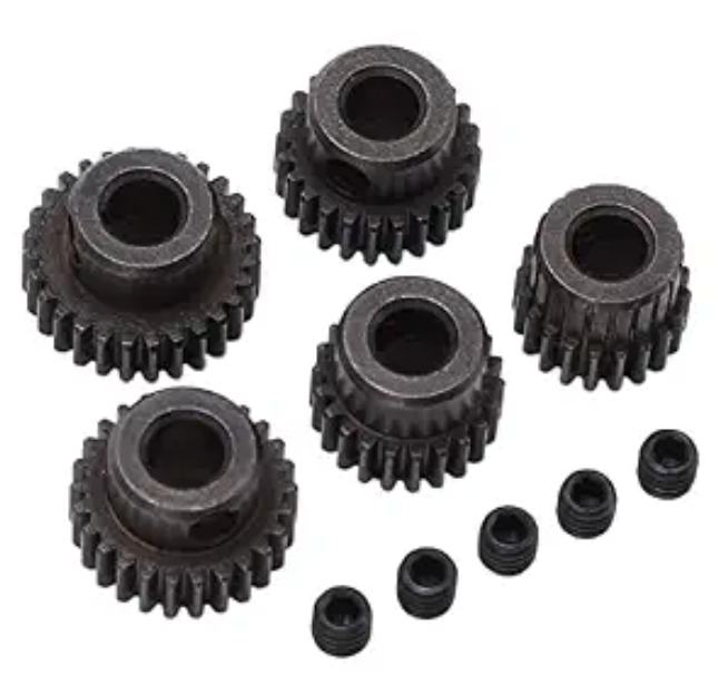
In my analysis, the pinion gears are clamped by an elastic sleeve that is expanded hydraulically. The hydraulic oil is nearly incompressible, so a small piston displacement produces a uniform pressure in the sealed annular chamber. This pressure acts on the outer surface of a thin-walled sleeve. The sleeve then contracts inward and presses the elastic expansion sleeve against the tooth tip circle of the pinion gears. Because the pressure is distributed uniformly around the circumference, the fixture provides automatic centering and repeatable radial clamping. I treated this as a coupled problem involving fluid pressure, elastic shell deformation, contact, and machining force balance.
Design Requirements and Functional Scheme
I first reviewed the machining process for the pinion gears. The end teeth are milled after the lower boss face and the outer cylindrical surface have been finish-turned. The axial locating datum is the lower boss face, and the radial locating datum is the outer cylindrical surface of the pinion gears. The fixture must therefore combine axial seating with radial hydraulic expansion. The main technical requirements I adopted are summarized in Table 1.
| Requirement | Target value | Purpose |
|---|---|---|
| Axial runout after clamping | < 0.005 mm | Ensure end tooth depth and cone angle consistency |
| Radial runout after clamping | < 0.005 mm | Maintain center position of pinion gears |
| Repeat locating accuracy | < 0.005 mm | Support batch production |
| Clamping principle | Hydraulic expansion | Uniform pressure and automatic centering |
| Workpiece datum | Outer cylinder and lower boss face | Match previous finishing datum |
| Machining method | Five-axis milling | Complete end teeth in one setup |
According to the six-point locating principle, I constrained five degrees of freedom by the hydraulic expansion contact on the outer cylinder of the pinion gears, and I constrained the remaining axial translation by a locating block. The thin-walled sleeve is the central elastic element. Its flange is fixed to the fixture body, and its two ends are sealed by O-rings. The elastic expansion sleeve has multiple symmetrical slots, so it can open and close quickly while transmitting the radial clamping force. This sleeve also protects the tooth tip circle of the pinion gears because the contact is distributed rather than concentrated.
Cutting Force and Clamping Force Balance
I estimated the milling force because the hydraulic clamping force must exceed the cutting load with a suitable safety margin. Using the machining parameters of the five-axis milling center and a carbide cutter, I applied the empirical milling force relationship:
$$F_c = 118 \, \frac{d_0^{1.0}}{n^{0.75} z^{0.85}} \, f_z^{-0.73} \, a_e^{0.1}$$
where \(F_c\) is the main cutting force, \(d_0\) is the cutter diameter, \(n\) is the spindle speed, \(z\) is the number of teeth, \(f_z\) is the feed per tooth, and \(a_e\) is the radial depth of cut. For the pinion gears fixture, the calculated main cutting force was approximately:
$$F_c = 277 \, \text{N}$$
I then related the feed force and radial force to the main cutting force using the ratios commonly used for milling:
$$F_f = 2.5 F_c$$
$$F_r = 3.8 F_c$$
The resulting cutting force components are listed in Table 2.
| Force component | Symbol | Value |
|---|---|---|
| Main cutting force | \(F_c\) | 277 N |
| Feed force | \(F_f\) | 105 N |
| Radial force | \(F_r\) | 77 N |
For safe clamping of pinion gears, I introduced a safety factor. The total safety factor was calculated as:
$$K = K_0 K_1 K_2 K_3 K_4 K_5$$
I selected the factors according to the workpiece material, machining condition, tool bluntness, cutting characteristics, clamping stability, and torque action. The chosen values are given in Table 3.
| Factor | Considered condition | Value |
|---|---|---|
| \(K_0\) | Workpiece material and machining allowance | 1.5 |
| \(K_1\) | Machining nature | 1.0 |
| \(K_2\) | Tool bluntness | 1.0 |
| \(K_3\) | Cutting characteristics | 1.2 |
| \(K_4\) | Clamping stability | 1.0 |
| \(K_5\) | Torque-only action | 1.0 |
The calculated product was \(K = 1.8\). Because the minimum recommended value for this type of fixture was 2.5, I used \(K = 2.5\). Hence the required hydraulic clamping force was:
$$W = K F_c = 2.5 \times 277 = 567.5 \, \text{N}$$
This value became my target for comparing theoretical, finite element, and experimental results. In my assessment, the hydraulic expansion fixture must generate at least this clamping force on the pinion gears during end tooth milling.
Theoretical Deformation of the Thin-Walled Sleeve
I treated the thin-walled sleeve as a cylindrical shell. When the wall thickness is much smaller than the minimum radius of curvature, the shell can be analyzed with thin-shell theory. I first used the membrane theory, which assumes no bending moments and no transverse shear. For a cylindrical shell, the membrane equations are:
$$\frac{\partial N_{\alpha}}{\partial \alpha} + \frac{\partial N_{\beta \alpha}}{\partial \beta} + q_1 = 0$$
$$\frac{\partial N_{\beta}}{\partial \beta} + \frac{\partial N_{\alpha \beta}}{\partial \alpha} + q_2 = 0$$
$$N_{\beta} = q_3 R$$
I assumed the sleeve was fixed at both ends, the middle surface radius was \(R\), the thickness was \(\delta\), and the effective load length was \(L\). Under uniform external pressure \(q_0\), the membrane solution for radial displacement is:
$$w = -\frac{q_0 R^2}{E \delta}$$
The direct membrane solution is useful, but it overestimates the displacement near the fixed ends because it neglects bending. Therefore, I corrected the result using the bending theory of cylindrical shells. The governing differential equation for axisymmetric deformation is:
$$\frac{d^4 w}{d\xi^4} + 4 w = \frac{4 q_0 R^2}{E \delta}$$
where the dimensionless coordinate is:
$$\xi = \frac{x}{\lambda}$$
and the characteristic length is:
$$\lambda = \frac{\sqrt{R \delta}}{\sqrt[4]{3(1-\mu^2)}}$$
The general solution is:
$$w = C_1 \sin \xi \sinh \xi + C_2 \sin \xi \cosh \xi + C_3 \cos \xi \sinh \xi + C_4 \cos \xi \cosh \xi + w^*$$
Because the deformation is symmetric, the odd terms vanish. For a sleeve fixed at one end and constrained at the other, the final corrected displacement can be written in the form:
$$w = \frac{q_0 R^2}{E \delta} \left[ 1 – 2 \frac{\sin \xi \cosh \xi – \cos \xi \sinh \xi}{\sin 2\xi + \sinh 2\xi} \sin \xi \sinh \xi – 2 \frac{\sin \xi \cosh \xi + \cos \xi \sinh \xi}{\sin 2\xi + \sinh 2\xi} \cos \xi \cosh \xi \right]$$
I evaluated this expression for three sleeve materials: 30CrMnSi, 42CrMo, and 65Mn. The geometric parameters were \(R = 286.03\) mm, \(\delta = 5.98\) mm, and \(L = 71.5\) mm. The pressure levels ranged from 1 MPa to 6 MPa. The theoretical radial deformation values are summarized in Table 4.
| Pressure | 30CrMnSi displacement (mm) | 42CrMo displacement (mm) | 65Mn displacement (mm) |
|---|---|---|---|
| 1 MPa | 0.015842 | 0.017814 | 0.016776 |
| 2 MPa | 0.034673 | 0.031519 | 0.035751 |
| 3 MPa | 0.051509 | 0.046529 | 0.054657 |
| 4 MPa | 0.065346 | 0.063839 | 0.066703 |
| 5 MPa | 0.086152 | 0.081448 | 0.086879 |
| 6 MPa | 0.108457 | 0.094887 | 0.101405 |
The theoretical trend was clear: as pressure increased, the radial deformation increased. For the same pressure level, the differences among the three materials were about 0.002 to 0.003 mm. A higher elastic modulus produced slightly smaller deformation. In my theoretical model, the pinion gears would be clamped by this controlled elastic deformation.
Finite Element Analysis of the Thin-Walled Sleeve
I used ANSYS Workbench to build a parameterized finite element model of the thin-walled sleeve. The three-dimensional model was created in Creo and then imported into Workbench. I defined the material properties for 30CrMnSi, 42CrMo, and 65Mn. The material data are shown in Table 5.
| Material | Elastic modulus (Pa) | Density (kg/m³) | Poisson ratio | Ultimate strength (kg/cm²) |
|---|---|---|---|---|
| 30CrMnSi | \(2.04 \times 10^{11}\) | 7850 | 0.290 | 11000 |
| 42CrMo | \(2.12 \times 10^{11}\) | 7820 | 0.280 | 11300 |
| 65Mn | \(2.09 \times 10^{11}\) | 7890 | 0.269 | 12000 |
I created a local cylindrical coordinate system because the pressure load acts on the outer cylindrical surface. The mesh was generated with adaptive mechanical sizing. I set the global body sizing to 5 mm and the loaded face sizing to 3 mm. The meshing produced 151,330 elements and 91,537 nodes. I fixed the lower face of the flange and the opposite contact face of the sleeve. The pressure load was applied to the outer cylindrical surface at the middle working region. The applied pressure levels are listed in Table 6.
| Load case | Pressure (MPa) |
|---|---|
| 1 | 1 |
| 2 | 2 |
| 3 | 3 |
| 4 | 4 |
| 5 | 5 |
| 6 | 6 |
After solving, I extracted the total deformation, equivalent stress, and equivalent strain. For all three materials, the deformation shape was similar. The displacement was small near the fixed boundaries, increased toward the middle, and reached a maximum at the center of the loaded region. The maximum stress also occurred at the middle of the outer wall. The finite element deformation results are given in Table 7.
| Pressure | 30CrMnSi max displacement (mm) | 42CrMo max displacement (mm) | 65Mn max displacement (mm) |
|---|---|---|---|
| 1 MPa | 0.016836 | 0.016015 | 0.017176 |
| 2 MPa | 0.033673 | 0.032019 | 0.034351 |
| 3 MPa | 0.050509 | 0.048029 | 0.051527 |
| 4 MPa | 0.067346 | 0.064039 | 0.068703 |
| 5 MPa | 0.084182 | 0.080048 | 0.085879 |
| 6 MPa | 0.101020 | 0.096058 | 0.103050 |
The maximum equivalent stress values are summarized in Table 8. I observed that the stress increased nearly linearly with pressure for each material. The differences among materials were small, which indicated that the material choice did not dominate the elastic response under the same geometry and pressure. This was an important point for pinion gears fixture design because it meant the sleeve geometry and pressure control were the primary factors.
| Pressure | 30CrMnSi max stress (MPa) | 42CrMo max stress (MPa) | 65Mn max stress (MPa) |
|---|---|---|---|
| 1 MPa | 26.102 | 26.603 | 26.438 |
| 2 MPa | 52.379 | 53.206 | 52.877 |
| 3 MPa | 78.569 | 79.809 | 79.315 |
| 4 MPa | 104.760 | 106.410 | 105.750 |
| 5 MPa | 130.950 | 133.020 | 132.190 |
| 6 MPa | 157.140 | 159.620 | 158.630 |
I then estimated the clamping torque and clamping force generated by the sleeve deformation. Using the outer diameter \(d_1 = 292.1\) mm, the friction coefficient between the fixture and the pinion gears \(\xi_1 = 0.2\), the loaded length \(l = 80\) mm, and the deformation-induced interface stress \(p_i\), I applied:
$$T_1 = 2 \pi \xi_1 \int_{0}^{l} p_i \frac{d_1}{2} dx$$
The equivalent clamping force was obtained from:
$$F = \frac{T_1 \times 2}{d_1}$$
The calculated clamping forces are listed in Table 9. I found that at 5 MPa, the 30CrMnSi sleeve produced about 596.68 N, the 42CrMo sleeve produced about 514.45 N, and the 65Mn sleeve produced about 523.62 N. These values were close to the required value of 567.5 N. Therefore, I selected 5 MPa as the working pressure for the hydraulic expansion fixture when clamping pinion gears.
| Pressure | 30CrMnSi clamping force (N) | 42CrMo clamping force (N) | 65Mn clamping force (N) |
|---|---|---|---|
| 1 MPa | 87.377 | 65.745 | 78.254 |
| 2 MPa | 134.450 | 125.280 | 119.340 |
| 3 MPa | 358.870 | 387.360 | 367.640 |
| 4 MPa | 505.690 | 498.250 | 487.350 |
| 5 MPa | 596.680 | 514.450 | 523.620 |
| 6 MPa | 728.580 | 687.850 | 659.660 |
Contact Analysis of the Complete Fixture
I also performed a contact analysis of the simplified hydraulic expansion fixture. The assembly included the thin-walled sleeve, the elastic expansion sleeve, and the pinion gears. I assigned 30CrMnSi to the thin-walled sleeve, 65Mn to the elastic expansion sleeve, and 18CrNiMo7-6 to the pinion gears. The material parameters are shown in Table 10.
| Material | Elastic modulus (Pa) | Density (kg/m³) | Poisson ratio |
|---|---|---|---|
| 30CrMnSi | \(2.04 \times 10^{11}\) | 7850 | 0.29 |
| 18CrNiMo7-6 | \(2.07 \times 10^{11}\) | 7850 | 0.30 |
| 65Mn | \(2.12 \times 10^{11}\) | 7820 | 0.28 |
I used frictional contact between the thin-walled sleeve and the elastic expansion sleeve, and between the elastic expansion sleeve and the pinion gears. The friction coefficient was set to 0.2, and the augmented Lagrange algorithm was used. The normal contact stiffness factor was 1.0. The mesh was generated with a free method and an element size of 0.005 m. The pressure load of 5 MPa was applied directly to the outer surface of the thin-walled sleeve. The finite element result for the complete fixture is given in Table 11.
| Result | Value |
|---|---|
| Maximum deformation | 0.085123 mm |
| Maximum equivalent stress | 163.58 MPa |
| Working pressure | 5 MPa |
The contact analysis showed that the deformation trend of the thin-walled sleeve agreed with the standalone sleeve analysis. The elastic expansion sleeve transmitted the radial displacement to the pinion gears in a distributed manner. I also observed that the maximum stress remained below the allowable stress of the selected material, so the fixture could clamp the pinion gears without plastic collapse under the assumed working pressure.
Experimental Validation
I designed and carried out a field validation test because simulation alone cannot fully represent manufacturing tolerances, assembly errors, and real contact conditions. The purpose of the test was threefold: first, to verify the theoretical deformation of the thin-walled sleeve; second, to verify the finite element results; and third, to support the manufacturing process of the sleeve for the pinion gears fixture. I used resistance strain gauges to measure the radial strain on a measuring rod inserted into a profile inspection workpiece. The strain gauges were connected in a Wheatstone bridge. The basic measurement relationship was:
$$\frac{\Delta R}{R} = K \varepsilon$$
Thus the strain was obtained as:
$$\varepsilon = \frac{\Delta R}{R K}$$
The deformation over the measuring length \(L\) was:
$$\Delta L = \varepsilon L$$
I used a static resistance strain instrument and a hydraulic pressure gauge. The test assembly consisted of the fixture body, the thin-walled sleeve, the elastic expansion sleeve, the profile inspection workpiece, and the measuring rod. Three sleeve materials were tested: 30CrMnSi, 42CrMo, and 45 steel. For each material, the pressure was increased from 1 MPa to 6 MPa. The radial deformation was recorded at three axial positions along the sleeve: near the upper end, at the middle, and near the lower end. The experimental results are listed in Table 12.
| Material | Position | 1 MPa | 2 MPa | 3 MPa | 4 MPa | 5 MPa | 6 MPa |
|---|---|---|---|---|---|---|---|
| 30CrMnSi | A1 | 0.00596 | 0.01595 | 0.01634 | 0.01986 | 0.03064 | 0.05203 |
| 30CrMnSi | A2 | 0.01678 | 0.03578 | 0.05123 | 0.06572 | 0.08125 | 0.10564 |
| 30CrMnSi | A3 | 0.00484 | 0.01524 | 0.01587 | 0.02035 | 0.03864 | 0.04428 |
| 42CrMo | B1 | 0.00386 | 0.02467 | 0.01564 | 0.02203 | 0.03401 | 0.05241 |
| 42CrMo | B2 | 0.01457 | 0.03785 | 0.04733 | 0.07523 | 0.08785 | 0.09756 |
| 42CrMo | B3 | 0.00336 | 0.02864 | 0.01256 | 0.02543 | 0.03508 | 0.05341 |
| 45 steel | C1 | 0.00342 | 0.01035 | 0.02054 | 0.04071 | 0.05640 | 0.07536 |
| 45 steel | C2 | 0.01415 | 0.03782 | 0.05347 | 0.06123 | 0.08786 | 0.10786 |
| 45 steel | C3 | 0.00257 | 0.01348 | 0.02085 | 0.04054 | 0.05790 | 0.06201 |
I found that the radial displacement varied along the axis. The middle position reached the maximum value, while the ends were constrained by the flange and the body. For the middle position, each 1 MPa increase in pressure produced about 0.017 to 0.020 mm additional deformation. I compared the 30CrMnSi experimental results with the finite element results, as shown in Table 13. The agreement was good, and the maximum deviation was within the expected measurement and assembly uncertainty. This confirmed that the theoretical thin-shell calculation and the finite element model were both reasonable for the hydraulic expansion fixture used on pinion gears.
| Pressure | FEA maximum deformation (mm) | Experimental maximum deformation (mm) |
|---|---|---|
| 1 MPa | 0.016836 | 0.01678 |
| 2 MPa | 0.033673 | 0.03578 |
| 3 MPa | 0.050509 | 0.05123 |
| 4 MPa | 0.067346 | 0.06572 |
| 5 MPa | 0.084182 | 0.08125 |
| 6 MPa | 0.101020 | 0.10564 |
The experimental campaign also showed that the material effect was secondary within the elastic range. The pinion gears were held by the combined action of the thin-walled sleeve, the elastic expansion sleeve, and the hydraulic pressure. The measured deformation supported the selection of 5 MPa as the working pressure. In my judgment, the test provided enough evidence that the hydraulic expansion principle can be used for precision clamping of pinion gears in batch production.
Reliability Analysis of the Thin-Walled Sleeve
After validating the deformation and clamping behavior, I analyzed the reliability of the thin-walled sleeve. The reliability function is defined as:
$$R(t) = P(T > t)$$
where \(T\) is the time to failure and \(t\) is the service time. I used the Six Sigma module in ANSYS Workbench. The random input variables were the sleeve thickness, elastic modulus, density, and working pressure. I assumed that these variables followed a normal distribution. The mean value was the design value, and the standard deviation was estimated by the coefficient of variation method:
$$\sigma = \alpha \mu$$
I selected a coefficient of variation of 0.05. The random input variables are summarized in Table 14.
| Variable type | Variable name | Distribution | Mean | Standard deviation |
|---|---|---|---|---|
| Geometric | Sleeve thickness \(L_1\) | Normal | 6 mm | 0.3 mm |
| Material | Elastic modulus \(E\) | Normal | \(2.06 \times 10^{11}\) Pa | \(1.03 \times 10^{10}\) Pa |
| Material | Density \(\rho\) | Normal | 7850 kg/m³ | 392.5 kg/m³ |
| Load | Pressure \(P\) | Normal | 5 MPa | 0.25 MPa |
The central composite design sampling method was used. The generated histograms for the random variables were close to normal distributions, and no large gaps or jumps appeared, so the sampling was sufficient. The sensitivity analysis showed that pressure had the strongest influence on the maximum stress and safety factor. Sleeve thickness was the second most important variable. Elastic modulus and density had a smaller influence. The sensitivity trend is summarized in Table 15.
| Input variable | Effect on maximum stress | Effect on safety factor | Relative importance |
|---|---|---|---|
| Pressure | Positive | Negative | Highest |
| Sleeve thickness | Negative | Positive | High |
| Elastic modulus | Slight positive | Slight negative | Low |
| Density | Very slight | Very slight | Lowest |
The cumulative distribution of the maximum stress showed that the probability of the maximum stress being below the allowable stress of 30CrMnSi was approximately 100%. The safety factor was also evaluated. The probability that the safety factor was below 1.9 was about 97.1%, which meant the safety factor was greater than 1.9 with a probability of about 97.1%. Therefore, I concluded that the thin-walled sleeve was reliable for clamping the pinion gears under the selected working pressure. The reliability results are summarized in Table 16.
| Output quantity | Criterion | Probability | Conclusion |
|---|---|---|---|
| Maximum stress | \(< 850\) MPa | Approximately 100% | Safe |
| Safety factor | \(> 1.9\) | Approximately 97.1% | Reliable |
| Overall reliability | No plastic collapse | Approximately 1.0 | Acceptable |
Fault Tree Analysis of the Hydraulic Expansion Fixture
I also used fault tree analysis to study the system-level reliability of the hydraulic expansion fixture. The top event was failure of the fixture during end tooth milling of pinion gears. I collected fault statistics and divided the failure modes into clamping function failure and locating function failure. The main events are listed in Table 17.
| Event code | Event definition | Event code | Event definition |
|---|---|---|---|
| T | Hydraulic expansion fixture failure | S7 | Axial locating failure |
| S1 | Clamping function failure | S8 | Insufficient hydraulic oil intake |
| S2 | Locating function failure | S9 | Hydraulic oil leakage |
| S3 | Oil pressure loading failure | S10 | Hydraulic cylinder failure |
| S4 | Pressure holding failure | S11 | Thin-walled sleeve deformation failure |
| S5 | Unloading failure | S12 | Low coaxiality between sleeve and elastic sleeve |
| S6 | Radial locating failure | S13 | Seal element failure |
| X1 | Insufficient pump oil | X8 | Push rod rebound failure |
| X2 | High oil circuit resistance | X9 | Fatigue plastic deformation of sleeve |
| X3 | Air in the sealed cavity | X10 | Quality problem |
| X4 | Excessive sleeve stiffness | X11 | Improper assembly |
| X5 | Seal aging | X12 | Low manufacturing accuracy |
| X6 | Seal wear | X13 | Locating block wear |
| X7 | Clearance caused by wear between sleeve and body |
Using the downward method, I derived the minimal cut sets. The calculation is summarized in Table 18.
| Step | 1 | 2 | 3 | 4 | 5 |
|---|---|---|---|---|---|
| Process | S1 | S3 | S8 | X1 | X1 |
| S2 | S4 | X3 | X2 | X2 | |
| S5 | X4 | X3 | X3 | ||
| S6 | S9 | X4 | X4 | ||
| S7 | S10 | S13 | X5 | ||
| S11 | X7 | X6 | |||
| S12 | X8 | X7 | |||
| X10 | X9 | X8 | |||
| X13 | X10 | X9 | |||
| X11 | X10 | X10 | |||
| X12 | X11 | X11 | |||
| X12 | X12 | ||||
| X13 | X13 |
The minimal cut sets were:
$$\{X1\}, \{X2\}, \{X3\}, \{X4\}, \{X5\}, \{X6\}, \{X7\}, \{X8\}, \{X9\}, \{X10\}, \{X11\}, \{X12\}, \{X13\}$$
Each basic event could independently cause the top event. However, hydraulic oil leakage appeared most frequently in the qualitative analysis. In my assessment, leakage is the most influential failure mode because it directly reduces the pressure acting on the thin-walled sleeve and therefore reduces the clamping force on the pinion gears. Seal aging, seal wear, and clearance caused by wear between the sleeve and the body are the main contributors. To improve the reliability of the hydraulic expansion fixture, I recommend regular inspection of seals, strict control of the fit clearance, cleaning of the oil circuit, and verification of the locating surface roughness. These measures are especially important when the fixture is used repeatedly for pinion gears in batch production.
Discussion and Practical Implications
From my study, the hydraulic expansion fixture offers several advantages for precision machining of pinion gears. It provides uniform radial pressure, automatic centering, and repeatable clamping. The thin-walled sleeve is the key element, and its deformation must be controlled within the elastic range. The theoretical shell calculation, finite element simulation, and field test all showed that the maximum deformation occurs at the middle of the loaded region. The working pressure of 5 MPa produced a clamping force close to the required value for the pinion gears. The material effect was small in the elastic range, so the sleeve thickness and pressure control are the main design variables. The reliability analysis indicated that the sleeve is safe, and the fault tree analysis identified hydraulic oil leakage as the most critical system-level failure mode.
For future work, I would extend the static analysis to dynamic clamping and cutting. The interaction between the milling force and the hydraulic clamping force should be studied under transient conditions. I would also examine manufacturing tolerances, surface roughness, and assembly eccentricity in more detail, because these factors affect the runout of the pinion gears. A more advanced contact model with thermal effects and wear could improve the prediction of long-term performance. Finally, I would develop a standardized manufacturing and inspection procedure for the thin-walled sleeve so that the hydraulic expansion fixture can be produced with consistent quality and used reliably for pinion gears in locomotive traction systems.
Summary of Key Results
| Item | Result |
|---|---|
| Main cutting force for pinion gears | 277 N |
| Safety factor | 2.5 |
| Required clamping force | 567.5 N |
| Selected working pressure | 5 MPa |
| Thin-walled sleeve maximum deformation at 5 MPa | 0.080 to 0.086 mm depending on material |
| Maximum equivalent stress at 5 MPa | about 131 to 133 MPa |
| Experimental middle-position deformation at 5 MPa | about 0.081 to 0.088 mm |
| Reliability of thin-walled sleeve | Approximately 1.0 |
| Most critical fault tree event | Hydraulic oil leakage |
I conclude that the hydraulic expansion precision fixture is a suitable technical solution for clamping pinion gears during end tooth milling. The coupled theoretical, numerical, and experimental approach gave consistent results. The fixture can achieve the required locating accuracy when the sleeve geometry, hydraulic pressure, seal condition, and assembly quality are properly controlled. The findings provide a practical basis for designing and manufacturing hydraulic expansion fixtures for pinion gears and for improving their reliability in repeated production.