
I first encountered this problem as a field issue affecting a parallel-shaft gearbox used in urban rail service. The gearbox had accumulated close to 1.2 million km when routine inspections began to show higher vibration and increased noise. When the unit was returned to the workshop and disassembled, I found that the pinion gears had suffered severe surface flaking and spalling on both the left and right tooth flanks. The damage was not isolated to one or two teeth. It appeared on nearly every tooth of the pinion gears, with the most severe regions located near the tooth ends and below the pitch line. The damaged zones formed long, triangular, strip-like patterns. I also reviewed the service feedback and found that the same failure mode had been reported in multiple cases. This made it clear that the problem was not a random manufacturing defect but a repeatable design and contact-condition issue involving the pinion gears.
Because the pinion gears are among the most heavily loaded components in the traction gearbox, their reliability directly affects traction performance and operating safety. The pinion gears connect the traction motor to the axle through the gear mesh, and they must simultaneously carry high torque, resist bending fatigue, and maintain stable tooth contact under variable load. When the contact pattern becomes concentrated at one end of the tooth, the local line load rises sharply, the contact stress increases, and the lubricating film becomes more difficult to maintain. Under those conditions, surface fatigue can initiate and propagate until flaking occurs. My objective was therefore to determine why the pinion gears were experiencing contact fatigue, to quantify the influence of system deformation and bearing clearance, and to develop an optimized tooth flank modification that would improve load distribution without harming bending strength or transmission behavior.
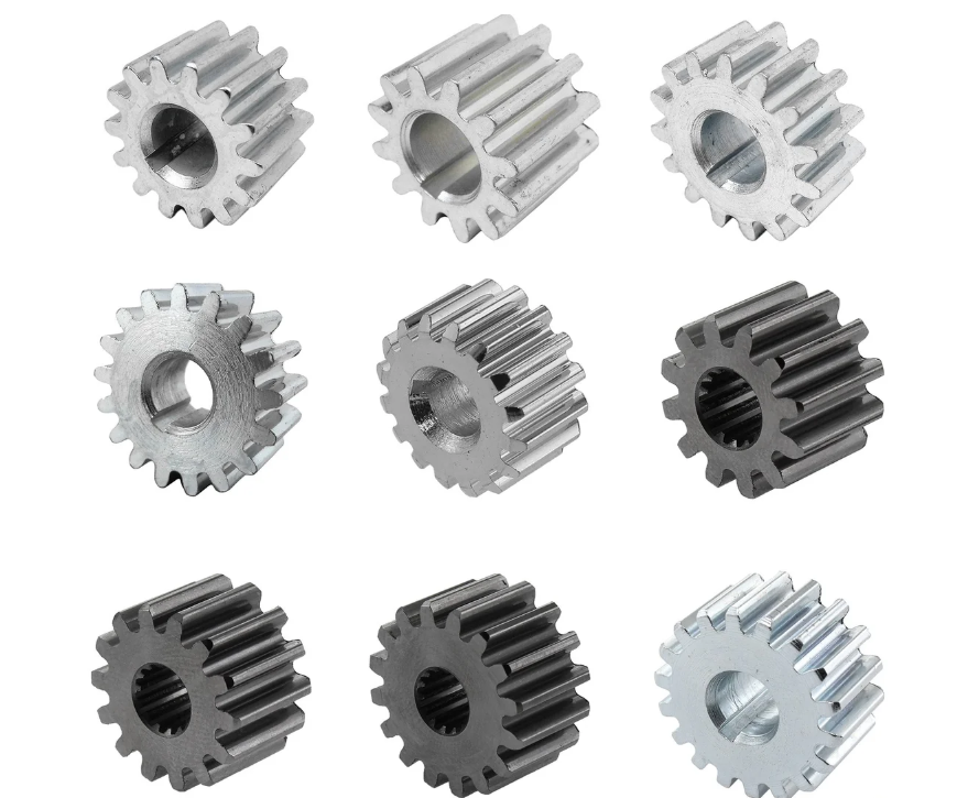
I approached the investigation in several stages. First, I documented the failure position and morphology on the pinion gears. Second, I checked the material, heat treatment, hardness, case depth, and internal quality to rule out raw material or heat-treatment causes. Third, I recalculated the original gear strength using the applicable international gear rating method. Fourth, I built a tooth contact model that included the actual bearing axial clearances and support stiffness. Fifth, I compared the calculated contact pattern with the physical damage on the pinion gears. Sixth, I optimized the flank modification by adding a spiral angle correction to the pinion gears. Finally, I validated the optimized design through a loaded gearbox test and a red-lead contact check.
The failure morphology was highly informative. The damaged regions on the pinion gears were concentrated near the tooth ends and extended along the flank in a diagonal direction. In a well-aligned gear mesh, the contact pattern should be reasonably centered along the face width and should shift only mildly under load. In this case, however, the contact pattern was strongly diagonal. That condition is often described as diagonal contact or edge-biased contact. It creates a local increase in line load and contact stress. Because the pinion gears had a relatively small number of teeth compared with the mating gear, they experienced more load cycles per revolution. That made the pinion gears especially sensitive to any contact stress concentration. The repeated passage of high stress over the same flank region eventually produced surface fatigue, and the fatigue cracks then propagated to form the observed flaking and spalling.
| Observed feature | Condition on failed pinion gears | Engineering implication |
|---|---|---|
| Flank affected | Left and right flanks | Both driving directions were affected |
| Tooth population | Most teeth showed damage | Systemic contact problem rather than isolated defect |
| Location | Near tooth ends, below pitch line | Edge loading and negative sliding contribution |
| Shape | Long triangular strips | Diagonal contact pattern |
| Service distance | Close to 1.2 million km | Fatigue-related failure under cumulative loading |
| Repeated occurrence | Multiple reported cases | Design modification required |
I then examined the original tooth profile and lead inspection reports. The pinion gears had been manufactured with tip relief and lead crowning. The mating gear had tip relief but no lead correction. The inspection results showed that the actual manufactured profiles and leads were consistent with the drawing requirements. In other words, the pinion gears had not failed because they were made outside the specified tolerances. The problem was that the specified modification was not sufficient for the real system deformation. Lead crowning can help avoid edge contact under moderate misalignment, but it cannot fully compensate a strong diagonal contact pattern caused by shaft bending, torsion, bearing clearance, and housing flexibility. The pinion gears needed a correction that acted along the helix direction, not only a symmetric crown along the face width.
I verified the chemical composition of the pinion gear material to determine whether any alloying element was outside the acceptable range. The material was a carburizing-grade Ni-Cr-Mo steel. The measured values satisfied the specification for all major elements. The carbon, silicon, manganese, phosphorus, sulfur, nickel, chromium, molybdenum, and aluminum contents were within the required limits. Phosphorus and sulfur were particularly low, which is beneficial for toughness and fatigue resistance. I did not find any evidence that the chemical composition contributed to the surface flaking on the pinion gears.
| Element | Specified range, mass fraction % | Measured value, mass fraction % | Assessment |
|---|---|---|---|
| C | 0.17 to 0.23 | 0.21 | Acceptable |
| Si | 0.15 to 0.40 | 0.24 | Acceptable |
| Mn | 0.40 to 0.70 | 0.52 | Acceptable |
| P | 0.020 maximum | 0.014 | Acceptable |
| S | 0.020 maximum | 0.001 | Acceptable |
| Ni | 1.60 to 2.00 | 1.62 | Acceptable |
| Cr | 0.35 to 0.65 | 0.46 | Acceptable |
| Mo | 0.20 to 0.30 | 0.24 | Acceptable |
| Al | 0.05 maximum | 0.02 | Acceptable |
I also checked nonmetallic inclusions and austenitic grain size. The inclusion rating met the high-quality steel requirement of the relevant standard. The grain size was fine enough to support good core toughness and fatigue performance. In a carburized pinion gear, fine grain size is important because it improves the resistance to crack initiation in the case and helps prevent sudden tooth fracture. The measured grain size did not indicate overheating or abnormal heat treatment. I therefore had no reason to suspect that the pinion gears had been exposed to a harmful thermal cycle during manufacturing.
| Quality item | Requirement | Result | Assessment |
|---|---|---|---|
| Nonmetallic inclusions | High-grade quality steel | Within specified class | Acceptable |
| Austenitic grain size | Not coarser than grade 6 for 70% of field | Met requirement | Acceptable |
| Surface hardness | 58 to 62 HRC | 59 to 61 HRC | Acceptable |
| Core hardness | 35 to 45 HRC | 38 to 43 HRC | Acceptable |
| Case depth at pitch diameter | 1.20 to 1.80 mm | 1.35 to 1.63 mm | Acceptable |
The hardness and case-depth results were especially important because surface flaking can sometimes be caused by insufficient case depth, excessive core hardness, or inadequate support beneath the hardened layer. In this case, however, the surface hardness, core hardness, and effective case depth all satisfied the design specification. The case was deep enough to support the contact stress, and the core was hard enough to resist plastic deformation but still tough enough to support the case. The pinion gears did not show evidence of soft case, grinding burn, or inadequate hardening.
I performed tensile and impact testing on specimens taken from the failed pinion gear material. The tensile strength, yield strength, and impact energy all met the requirements. I also checked the undamaged teeth with magnetic particle inspection, ultrasonic inspection, and temper-burn inspection. No unacceptable surface or internal defects were found. These results were significant because they eliminated raw material defects, forging defects, heat-treatment defects, and machining cracks as primary causes. The pinion gears had been manufactured to the required quality level. The failure was therefore driven by the operating contact stress and the tooth contact pattern.
| Property | Requirement | Measured result | Assessment |
|---|---|---|---|
| Tensile strength | Specified minimum | Met | Acceptable |
| Yield strength | Specified minimum | Met | Acceptable |
| Impact energy | Specified minimum | Met | Acceptable |
| Magnetic particle inspection | No unacceptable indication | No rejection | Acceptable |
| Ultrasonic inspection | No unacceptable internal defect | No rejection | Acceptable |
| Temper-burn inspection | No unacceptable burn | No rejection | Acceptable |
After ruling out material and heat-treatment causes, I turned to the design rating. I modeled the gear pair using the international involute cylindrical gear load capacity method. I used the startup condition as the governing case because it produces the highest torque and therefore the highest contact stress. The design life was taken as 10,000 hours of startup operation. The material fatigue limits were selected for carburized and hardened gear steel at the appropriate quality level: a contact fatigue limit of 1,500 MPa and a bending fatigue limit of 500 MPa. I included tooth modification and load distribution in the model. The original gear parameters are summarized in the table below.
| Parameter | Pinion gears | Mating gear |
|---|---|---|
| Normal module, mm | 4.5 | 4.5 |
| Number of teeth | 17 | 131 |
| Gear ratio | 7.7058 | 7.7058 |
| Normal pressure angle, deg | 20 | 20 |
| Helix angle, deg | 21 | 21 |
| Face width, mm | 94 | 90 |
The gear ratio is defined by the ratio of the number of teeth:
$$ i = \frac{z_2}{z_1} = \frac{131}{17} = 7.7058 $$
The reference pitch diameter of each gear follows from the normal module, the number of teeth, and the helix angle:
$$ d = \frac{m_n z}{\cos \beta} $$
For the pinion gears, the small number of teeth means that the same tooth flank is loaded many times per output revolution. The contact stress is calculated from the standard relationship:
$$ \sigma_H = Z_H Z_E Z_\varepsilon Z_\beta \sqrt{\frac{F_t}{d_1 b} \frac{u+1}{u} K_A K_V K_{H\beta} K_{H\alpha}} $$
Here, \(F_t\) is the tangential load, \(d_1\) is the pinion reference diameter, \(b\) is the face width, \(u\) is the gear ratio, \(K_A\) is the application factor, \(K_V\) is the dynamic factor, \(K_{H\beta}\) is the face load distribution factor, and \(K_{H\alpha}\) is the transverse load distribution factor. The face load distribution factor \(K_{H\beta}\) is especially important for this failure because it directly reflects how unevenly the load is distributed across the face width. A high \(K_{H\beta}\) value means that part of the tooth carries much more load than the rest of the flank. That condition was present in the original pinion gears.
The bending stress is calculated in a similar manner:
$$ \sigma_F = \frac{F_t}{b m_n} Y_F Y_S Y_\beta K_A K_V K_{F\beta} K_{F\alpha} $$
The safety factors are defined as the ratio of the allowable stress to the calculated stress:
$$ S_H = \frac{\sigma_{H,\lim}}{\sigma_H} $$
$$ S_F = \frac{\sigma_{F,\lim}}{\sigma_F} $$
The original design calculation produced the safety factors shown below. The pinion gears had a contact safety factor of 0.809 on the left flank and 0.917 on the right flank. Those values are below the recommended minimum for low reliability and far below the recommended minimum for general reliability. The bending safety factors were higher, which indicates that bending was not the primary failure mode. The contact stress was the limiting condition, and the left flank was worse than the right flank.
| Gear | Contact safety factor, left | Contact safety factor, right | Bending safety factor, left | Bending safety factor, right |
|---|---|---|---|---|
| Pinion gears | 0.809 | 0.917 | 1.447 | 1.803 |
| Mating gear | 0.970 | 1.099 | 1.274 | 1.586 |
For comparison, the recommended minimum safety factors from the applicable rating practice are listed below. A contact safety factor below 0.85 corresponds to low reliability, while a value between 1.00 and 1.10 corresponds to general reliability. The original pinion gears did not reach general reliability on either flank. The left flank was even below the low-reliability threshold, which is consistent with the observed early surface fatigue and flaking. This calculation alone was enough to show that the pinion gears were at risk, but it did not explain why the contact pattern was so strongly biased. I needed a tooth contact analysis that included the gearbox system.
| Reliability level | Minimum contact safety factor | Minimum bending safety factor |
|---|---|---|
| High reliability | 1.50 to 1.60 | 2.00 |
| Relatively high reliability | 1.25 to 1.30 | 1.60 |
| General reliability | 1.00 to 1.10 | 1.25 |
| Low reliability | 0.85 | 1.00 |
I then built a contact model to evaluate the actual meshing behavior. The original design specified an axial clearance of 0.20 to 0.25 mm for the two tapered roller bearings on the pinion shaft. The mating gear shaft bearings had an axial clearance of 0.10 to 0.15 mm. I used the mid-range values in the model and calculated the loaded contact pattern for both startup and braking conditions. The model included shaft bending, torsional deflection, bearing stiffness, housing support stiffness, and the influence of the axial clearances. Under load, the pinion shaft deflected in a way that rotated the tooth contact diagonally across the face width. The left and right flanks behaved differently because the direction of the tangential force reversed between driving and braking.
The results showed that the original pinion gears had a severe diagonal contact pattern. On the right flank, the load shifted toward the wheel side. On the left flank, the load shifted toward the motor side. The left flank was more severely loaded. The face load distribution factor reached \(K_{H\beta} = 1.635\). The maximum contact stress in the startup condition on the left flank reached 1,526.0 MPa, which exceeded the allowable contact stress of 1,301.9 MPa. The calculated high-stress region coincided with the physical damage on the pinion gears. That agreement gave me confidence that the model was capturing the real failure mechanism.
| Condition | Flank | Contact bias | Face load distribution factor | Maximum contact stress, MPa | Allowable contact stress, MPa |
|---|---|---|---|---|---|
| Startup | Left | Toward motor side | 1.635 | 1,526.0 | 1,301.9 |
| Startup | Right | Toward wheel side | 1.635 | Below left-flank maximum | 1,301.9 |
| Braking | Left | Toward motor side | High | High | 1,301.9 |
| Braking | Right | Toward wheel side | High | High | 1,301.9 |
The diagonal contact pattern can be understood through the mesh misalignment components. In a loaded gear pair, the effective misalignment along the face width is not only the manufacturing lead deviation. It also includes the deflection of shafts, bearings, and housing, as well as the initial bearing clearance. A simplified expression for the effective mesh misalignment is:
$$ F_{\beta x} = F_{\beta} + F_{\beta bx} + F_{\beta m} $$
where \(F_{\beta}\) is the initial lead deviation, \(F_{\beta bx}\) is the equivalent misalignment caused by shaft and bearing deformation, and \(F_{\beta m}\) is the additional misalignment caused by manufacturing and assembly variations. In the original pinion gears, the lead crowning was intended to compensate for \(F_{\beta}\), but it did not adequately compensate the system-dependent term \(F_{\beta bx}\). The bearing axial clearances allowed the pinion shaft to shift and tilt under load. The shaft bending and torsion further rotated the tooth contact. The result was a load concentration near the tooth ends. Because the pinion gears had a narrow face width relative to the load, even a small angular misalignment produced a significant shift in the contact pattern.
I also considered the influence of the contact pattern on specific sliding. Surface fatigue is more likely in regions where the sliding velocity is high and the lubricating film is thin. In the original pinion gears, the damaged region was below the pitch line, where negative specific sliding occurs. The specific sliding at a point on the flank can be expressed as:
$$ \sigma_s = \frac{v_{s1} – v_{s2}}{v_{t1}} $$
where \(v_{s1}\) and \(v_{s2}\) are the sliding velocities of the two flanks and \(v_{t1}\) is the tangential velocity of the pinion. The combination of high contact stress, negative sliding, and a load concentration near the tooth end created favorable conditions for micropitting, pitting, and eventual flaking. The material and heat treatment were adequate, but the contact mechanics were not. The pinion gears were being asked to carry a load that was concentrated on a small portion of the flank.
Based on these findings, I concluded that the primary cause of the pinion gear failure was uneven tooth contact caused by system deformation and bearing clearance. The original lead crowning was not sufficient to center the contact pattern under the actual operating loads. The pinion gears needed a modification that would introduce a controlled helix correction. A helix correction changes the effective pressure angle along the face width and shifts the contact pattern in the direction needed to compensate the system misalignment. In effect, it creates a deliberate opposite misalignment so that the loaded contact pattern becomes more centered.
The optimization concept was therefore straightforward: I retained the original lead crowning but added a spiral angle correction to the pinion gears. The mating gear remained at a helix angle of 21.000 degrees. The pinion gears were modified to a helix angle of 20.974 degrees. The difference is small, but over the face width it produces a controlled axial correction that counteracts the diagonal contact. The helix correction can be estimated as:
$$ \Delta \beta = \beta_{pinion} – \beta_{gear} = 20.974^\circ – 21.000^\circ = -0.026^\circ $$
The corresponding axial correction over the face width is approximately:
$$ \Delta x = b \tan(\Delta \beta) \approx 94 \tan(0.026^\circ) \approx 0.0427 \text{ mm} $$
That small correction is enough to shift the loaded contact pattern toward the center of the face width when the system deflection is included. The original lead crowning controlled the contact at the tooth ends, while the added helix correction controlled the diagonal bias. Together, they produced a more uniform load distribution across the face width. I also evaluated the left and right flanks separately because the system deflection changed with the direction of power flow. The left and right modifications were therefore defined as separate three-dimensional flank surfaces. This ensured that both driving directions would benefit from the correction.
| Parameter | Original pinion gears | Optimized pinion gears |
|---|---|---|
| Normal module, mm | 4.5 | 4.5 |
| Number of teeth | 17 | 17 |
| Original helix angle, deg | 21.000 | 21.000 nominal before correction |
| Modified helix angle, deg | Not applied | 20.974 |
| Lead crowning | Applied | Retained |
| Helix correction | Not applied | Applied |
| Tip relief | Applied | Retained |
After defining the optimized flank geometry, I recalculated the tooth contact and strength. The optimized contact analysis showed a much more centered pattern. The face load distribution factor dropped from 1.635 to 1.2. That reduction is significant because the contact stress is proportional to the square root of the load distribution factor. A lower \(K_{H\beta}\) directly reduces the maximum contact stress. The maximum contact stress after optimization was 1,189 MPa, which is a reduction of approximately 22% compared with the original 1,526 MPa. The optimized maximum stress is also below the allowable contact stress of 1,301.9 MPa, which means the pinion gears now have a positive margin in contact.
| Quantity | Original design | Optimized design | Change |
|---|---|---|---|
| Face load distribution factor, \(K_{H\beta}\) | 1.635 | 1.200 | 26.6% reduction |
| Maximum contact stress, MPa | 1,526 | 1,189 | 22.1% reduction |
| Contact pattern | Diagonal and edge-biased | Centered and uniform | Improved |
| Allowable contact stress, MPa | 1,301.9 | 1,301.9 | Reference |
| Contact stress margin | Negative | Positive | Improved |
The optimized safety factors also improved substantially. The pinion gear contact safety factor increased to 1.095 on the left flank and 1.096 on the right flank. Those values fall within the general reliability range. The bending safety factors increased to 2.457 and 2.459, which is well above the high-reliability requirement. The mating gear also showed improved contact and bending safety factors. The optimization therefore improved the contact condition without reducing bending capacity. In fact, the more uniform load distribution also reduced the peak bending stress at the tooth root because the load was no longer concentrated at one end of the face width.
| Gear | Contact safety factor, left | Contact safety factor, right | Bending safety factor, left | Bending safety factor, right |
|---|---|---|---|---|
| Optimized pinion gears | 1.095 | 1.096 | 2.457 | 2.459 |
| Optimized mating gear | 1.313 | 1.313 | 2.162 | 2.164 |
The fatigue life improvement can be estimated using the inverse power relationship between contact stress and contact fatigue life:
$$ L_{10} \propto \left( \frac{\sigma_{H,\lim}}{\sigma_H} \right)^p $$
For carburized gear steels, the exponent \(p\) is often taken in the range of 6 to 7 for contact fatigue. Using \(p = 6.8\), the ratio of the original stress to the optimized stress gives:
$$ \frac{L_{10,opt}}{L_{10,orig}} \approx \left( \frac{1526}{1189} \right)^{6.8} \approx 5.4 $$
This indicates that the optimized pinion gears could achieve roughly five times the contact fatigue life of the original design under the same load spectrum, assuming all other conditions remain equal. Even if the actual improvement is lower because of lubrication, surface finish, and operating variability, the reduction in peak contact stress is clearly beneficial. The pinion gears move from a negative contact margin to a positive contact margin, which is the most important change for preventing surface flaking.
I then validated the optimized design through a loaded gearbox test. A new pinion gear set was manufactured according to the optimized helix correction. The flanks were coated with red lead, and the gearbox was assembled using the standard assembly procedure. The contact pattern test was performed on a gearbox comprehensive performance test bench. The test bench used two gearboxes connected through a coupling at the pinion shaft. A load motor and a drive motor were connected to the axle ends. By adjusting the speed and torque of the motors, I could apply startup and braking loads in both directions.
| Test condition | Speed, r/min | Torque, N·m | Duration, min |
|---|---|---|---|
| Forward startup | +1008 | 450 | 40 |
| Forward startup | +1008 | 900 | 40 |
| Forward startup | +1008 | 1350 | 40 |
| Forward startup | +1008 | 1800 | 40 |
| Reverse braking | -1008 | 450 | 40 |
| Reverse braking | -1008 | 900 | 40 |
| Reverse braking | -1008 | 1350 | 40 |
| Reverse braking | -1008 | 1800 | 40 |
During the tests, I monitored temperature rise, vibration, and noise. The temperature at each measurement point remained normal. The sound power results were below the technical requirement of 98 dB(A) for all conditions. The vibration velocity at the gearbox measurement points remained below the limit of 18 mm/s. These results indicated that the optimized pinion gears did not introduce any undesirable dynamic behavior. The gearbox operated smoothly, and the contact pattern remained stable under load.
| Direction | Speed, r/min | Torque, N·m | Measured sound power, dB(A) | Requirement, dB(A) |
|---|---|---|---|---|
| Forward | +1008 | 450 | 94.62 | 98 maximum |
| Forward | +1008 | 900 | 93.50 | 98 maximum |
| Forward | +1008 | 1350 | 93.03 | 98 maximum |
| Forward | +1008 | 1800 | 92.85 | 98 maximum |
| Reverse | -1008 | 450 | 93.63 | 98 maximum |
| Reverse | -1008 | 900 | 92.54 | 98 maximum |
| Reverse | -1008 | 1350 | 92.05 | 98 maximum |
| Reverse | -1008 | 1800 | 91.87 | 98 maximum |
| Direction | Speed, r/min | Measurement point | Vibration velocity, mm/s | Requirement, mm/s |
|---|---|---|---|---|
| Forward | +1008 | Gearbox axial | 2.15 | 18 maximum |
| Forward | +1008 | Gearbox vertical | 3.45 | 18 maximum |
| Forward | +1008 | Pinion axial | 3.28 | 18 maximum |
| Forward | +1008 | Pinion vertical | 1.85 | 18 maximum |
| Reverse | -1008 | Gearbox axial | 1.62 | 18 maximum |
| Reverse | -1008 | Gearbox vertical | 3.40 | 18 maximum |
| Reverse | -1008 | Pinion axial | 1.80 | 18 maximum |
| Reverse | -1008 | Pinion vertical | 3.28 | 18 maximum |
After the loaded test, I opened the inspection cover and examined the red-lead contact pattern on the pinion gears. The contact area was uniform along the face width, with no abnormal edge contact at either end. The red lead was worn evenly, which indicated that the load was distributed across the full face width. I then wiped the flanks and inspected the tooth surfaces. The flanks were bright and smooth, with no signs of scoring, scuffing, or local distress. The tooth tips and roots were clean and free from burrs. The optimized pinion gears had produced the intended contact pattern.
The test results confirmed the calculations. The optimized pinion gears achieved a centered contact pattern, a lower face load distribution factor, and a lower maximum contact stress. The gearbox also met the temperature, vibration, and noise requirements. The improvement was not limited to one operating direction. Both the forward startup condition and the reverse braking condition showed acceptable behavior. That is important because the original failure occurred on both the left and right flanks. The helix correction addressed the root cause of the diagonal contact rather than merely masking the symptom.
I also considered the manufacturing feasibility of the optimized pinion gears. The helix correction is small, and it can be produced with standard gear grinding or honing equipment. The inspection of the modified flanks can be performed using the same lead and profile inspection methods used for the original pinion gears. The optimization does not require a change in material, heat treatment, or basic tooth geometry. It only changes the flank surface in a controlled way. That makes it practical for both new production and field replacement. The mating gear can remain unchanged, which reduces the cost and complexity of the solution.
From a design perspective, the case highlights the importance of evaluating the complete system rather than only the gear pair. The original design used lead crowning, which is a common and effective modification. However, lead crowning is most effective when the misalignment is symmetric or moderate. When the system produces a strong diagonal contact pattern, a helix correction is needed. The pinion gears are particularly sensitive because they have fewer teeth and therefore experience more load cycles. A small improvement in contact stress can produce a large improvement in fatigue life. In this case, the 22% reduction in maximum contact stress corresponds to a substantial increase in predicted life.
The analysis also shows why material and heat-treatment checks alone are not enough to explain a surface fatigue failure. The pinion gears met the chemical composition, inclusion, grain size, hardness, case depth, tensile, impact, and nondestructive inspection requirements. If I had stopped at material verification, I might have concluded that the pinion gears were acceptable and that the failure was caused by abnormal operation. The contact analysis revealed that the design was the limiting factor. The pinion gears were manufactured correctly, but they were not designed with sufficient helix correction for the actual system deflection.
Another important observation is the relationship between bearing clearance and contact pattern. The pinion shaft bearings had an axial clearance of 0.20 to 0.25 mm. The mating gear bearings had an axial clearance of 0.10 to 0.15 mm. These clearances are not unusual, but under high torque they allow the shafts to shift and tilt. The resulting change in the effective helix angle is small in absolute terms, but it is large enough to shift the contact pattern across a 94 mm face width. The contact analysis showed that the original pinion gears were sensitive to this shift. The optimized design reduced that sensitivity by introducing a compensating helix correction. This is a robust approach because it addresses the system behavior at the design stage.
I also examined the effect of load direction. In a parallel-shaft gearbox, the direction of the tangential force reverses when the machine operates in the opposite direction. That reversal changes the direction of shaft bending and the resulting contact bias. The original pinion gears showed different contact patterns on the left and right flanks. The left flank was more severely loaded in the startup condition, while the right flank was more severely loaded in the opposite direction. The optimized design accounted for both directions. The helix correction was applied in a way that centered the contact for both driving and braking. This is why the optimized pinion gears performed well in both the forward and reverse tests.
For future designs, I would recommend the following steps. First, calculate the gear rating with the actual load spectrum, not only the nominal torque. Second, include the bearing axial clearance and support stiffness in the contact model. Third, evaluate the contact pattern for both driving directions. Fourth, compare the calculated high-stress region with any field failures. Fifth, apply lead crowning and helix correction together when the system shows diagonal contact. Sixth, validate the design with a loaded contact pattern test. These steps are especially important for pinion gears because they are the most highly loaded and most frequently loaded gears in the system.
The optimized pinion gears now have a contact safety factor above 1.09, a bending safety factor above 2.45, and a maximum contact stress below the allowable limit. The face load distribution factor is 1.2 instead of 1.635. The contact pattern is centered and uniform. The test results confirm that the gearbox operates within the temperature, vibration, and noise requirements. The pinion gears no longer show the diagonal edge loading that caused the original surface flaking. The solution is practical, manufacturable, and compatible with the existing mating gear.
In summary, I identified the failure mechanism of the pinion gears as contact fatigue caused by uneven tooth contact. The original lead crowning was insufficient to compensate the system deformation and bearing clearance. The resulting diagonal contact produced a high face load distribution factor and a maximum contact stress above the allowable limit. I optimized the pinion gears by adding a spiral angle correction while retaining the original lead crowning and tip relief. The optimized design reduced the face load distribution factor from 1.635 to 1.2 and reduced the maximum contact stress from 1,526 MPa to 1,189 MPa, a reduction of approximately 22%. The optimized safety factors moved the pinion gears into the general reliability range. The loaded gearbox test confirmed a uniform contact pattern, acceptable sound power, acceptable vibration, and normal temperature rise. The optimized pinion gears therefore provide a reliable solution for preventing surface flaking and improving the service life of the gearbox.
| Investigation stage | Key finding | Action | Result |
|---|---|---|---|
| Failure documentation | Flaking on both flanks of pinion gears | Record location and morphology | Diagonal contact suspected |
| Material verification | Composition, inclusions, grain size acceptable | Rule out material cause | No material defect |
| Heat-treatment verification | Hardness and case depth acceptable | Rule out heat-treatment cause | No heat-treatment defect |
| Original rating | Contact safety factor below general reliability | Recalculate with load spectrum | Contact fatigue risk confirmed |
| Contact analysis | Diagonal contact, \(K_{H\beta}=1.635\) | Include bearing clearance and stiffness | Maximum stress 1,526 MPa |
| Optimization | Helix correction needed | Add spiral angle modification to pinion gears | \(K_{H\beta}=1.2\), maximum stress 1,189 MPa |
| Test validation | Uniform red-lead contact | Run loaded gearbox test | Vibration, noise, and temperature acceptable |
| Performance indicator | Original pinion gears | Optimized pinion gears | Assessment |
|---|---|---|---|
| Contact safety factor, left | 0.809 | 1.095 | Improved to general reliability |
| Contact safety factor, right | 0.917 | 1.096 | Improved to general reliability |
| Bending safety factor, left | 1.447 | 2.457 | High reliability |
| Bending safety factor, right | 1.803 | 2.459 | High reliability |
| Face load distribution factor | 1.635 | 1.200 | Substantial improvement |
| Maximum contact stress, MPa | 1,526 | 1,189 | 22% reduction |
| Contact pattern | Diagonal, edge-biased | Centered, uniform | Failure mechanism removed |
| Predicted relative life | Reference | Approximately 5.4 times | Substantial life improvement |
I consider the optimized design to be a successful example of using system-level contact analysis to solve a persistent field problem in pinion gears. The failure was not caused by a single manufacturing error. It was caused by the interaction of load, shaft deformation, bearing clearance, and insufficient helix correction. By quantifying that interaction and modifying the pinion gear flanks accordingly, I was able to reduce the peak contact stress and produce a uniform contact pattern. The test results verified the calculation, and the optimized pinion gears are now better suited for long-term service. This approach can be applied to other gearboxes where pinion gears show diagonal contact, edge loading, or early surface fatigue.
The broader lesson is that pinion gears should not be treated as isolated components. Their behavior depends on the entire transmission system. The shaft, bearings, housing, and mating gear all influence the contact pattern. When a pinion gear fails by surface flaking, the design team should examine the loaded contact pattern, not only the material and heat treatment. In this case, the material was acceptable, the heat treatment was acceptable, and the manufacturing inspection was acceptable. The design modification was the missing step. Adding a small helix correction to the pinion gears changed the contact pattern from diagonal to centered and reduced the maximum contact stress by 22%. That change was enough to move the pinion gears from low reliability to general reliability and to prevent the recurrence of surface flaking.
I also note that the optimized design retains the original lead crowning. This is important because lead crowning still provides protection against edge contact when the load is light or when the system alignment varies. The helix correction and lead crowning work together. The lead crowning controls the local edge condition, while the helix correction controls the global diagonal bias. This combined modification is more effective than either one alone for pinion gears operating under high torque and variable direction. The same principle can be applied to other heavily loaded gear pairs in rail traction, industrial drives, and marine transmissions.
The validation test was performed with red lead, which is a practical and widely accepted method for checking contact patterns. The red lead showed a uniform contact band along the face width. The absence of edge contact was especially encouraging because the original failure had initiated near the tooth ends. After the red lead was wiped away, the flanks were bright and smooth. There was no evidence of local overheating, scoring, or plastic deformation. The gearbox also passed the temperature, vibration, and noise checks. These results confirmed that the optimized pinion gears are not only stronger in calculation but also stable in operation.
In conclusion, I found that the original pinion gears failed because the loaded contact pattern was diagonally biased. The bias produced a high local line load and a contact stress above the allowable limit. The material and heat treatment were not the cause. The solution was to add a spiral angle correction to the pinion gears while keeping the original lead crowning and tip relief. The optimized pinion gears achieved a face load distribution factor of 1.2, a maximum contact stress of 1,189 MPa, and safety factors within the general reliability range. The loaded test confirmed a uniform contact pattern and acceptable dynamic behavior. The optimized pinion gears are therefore recommended for production and field replacement.