
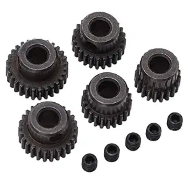
I investigated a batch of 20Cr13 pinion gears that fractured at the root during tightening of a clamping bolt. The pinion gears had already passed a hardness acceptance check and were released to assembly. The fracture occurred before a torque wrench was applied, so the failure load was far below the expected tightening load. I examined the failed pinion gears by macroscopic observation, chemical composition analysis, hardness testing, metallographic examination, scanning electron microscopy, and elemental mapping. My purpose was to determine why the pinion gears failed at such a low load and to identify practical controls that would prevent recurrence.
The pinion gears were used in a drive arrangement in which a hexagonal steel shaft passed through the gear root and was clamped by a bolt from below. The root region was therefore subjected to a combination of bolt preload, bending, and local stress concentration. Because the fracture happened during assembly, I regarded the pinion gears as having insufficient resistance to a modest tensile and bending load. The fracture surface had a porcelain-like gray appearance without a strong metallic luster, and I did not see a clear single initiation site under low-magnification inspection. The location was the thinnest and most highly stressed section of the pinion gears.
| Item | Condition or observation | Engineering significance for the pinion gears |
|---|---|---|
| Material designation | 20Cr13 martensitic stainless steel | Expected to provide a balance of strength, hardness, and corrosion resistance after quenching and tempering. |
| Required heat treatment | Quenching and tempering | The pinion gears should contain tempered martensite or sorbite, not an annealed or overheated structure. |
| Required hardness | 20 to 30 HRC | The hardness window is broad enough that an unacceptable microstructure can still pass the acceptance test. |
| Fracture location | Root of the pinion gears | The root is a geometric stress raiser and the thinnest section. |
| Fracture stage | Bolt tightening before use of a torque wrench | The applied load was low, indicating a material or process defect rather than normal service overload. |
| Macroscopic fracture appearance | Porcelain-like, gray, no obvious metallic luster, no clear crack origin | This appearance is consistent with a brittle fracture of a weakened microstructure. |
| Hardness acceptance | Passed before assembly | Hardness alone did not detect the damaging grain-boundary condition in the pinion gears. |
I first considered the mechanical loading path. During tightening, the bolt produces a preload force that clamps the hexagonal shaft against the pinion gear root. The nominal torque is related to the preload by the well-known torque-preload relation:
$$T = K D F_i$$
where \(T\) is the tightening torque, \(K\) is the nut factor, \(D\) is the nominal bolt diameter, and \(F_i\) is the bolt preload. The root stress is not simply the preload divided by the area. Because the root contains a geometric discontinuity, the local maximum stress is increased by a stress concentration factor:
$$\sigma_{\max} = K_t \sigma_{\text{nom}}$$
For a brittle material or a material with weakened grain boundaries, fracture occurs when the local maximum stress reaches the local fracture strength:
$$\sigma_{\max} \ge \sigma_f$$
In the failed pinion gears, the applied load was low, so \(\sigma_f\) must have been unusually low. The metallurgical evidence showed that the low fracture strength was caused by overheating and overburning at the grain boundaries. The grain boundaries were not effective load-transfer paths. Instead, they became crack paths, and the pinion gears fractured in an intergranular manner.
I performed chemical composition analysis to determine whether the pinion gears met the specified 20Cr13 steel composition. The measured values were within the standard ranges for the major elements. This result was important because it ruled out a gross material mix-up or a major alloying error as the primary cause of the fracture. The chemical composition of the pinion gears is summarized below.
| Element | Measured mass fraction (%) | Specified range (%) | Assessment for the pinion gears |
|---|---|---|---|
| C | 0.23 | 0.16 to 0.25 | Within specification. |
| Si | 0.42 | ≤ 1.00 | Within specification. |
| Mn | 0.53 | ≤ 1.00 | Within specification. |
| P | 0.022 | ≤ 0.040 | Within specification. |
| S | 0.008 | ≤ 0.035 | Within specification. |
| Cr | 12.12 | 12.00 to 14.00 | Within specification but near the lower limit. |
| Ni | 0.18 | ≤ 0.60 | Within specification. |
Because the composition was acceptable, I focused on the thermal history and microstructure of the pinion gears. I tested hardness at several locations near the fracture. The results were between 21 and 26 HRC, which satisfied the 20 to 30 HRC requirement. However, the hardness values showed noticeable scatter. A scattered hardness distribution often indicates a nonuniform microstructure, mixed phases, or an imperfect heat treatment. For the pinion gears, the hardness acceptance did not prove that the microstructure was suitable for the root loading condition.
| Measurement location on the pinion gears | Hardness (HRC) | Requirement (HRC) | Observation |
|---|---|---|---|
| Near fracture root | 21 | 20 to 30 | Acceptable but low. |
| Adjacent root region | 26 | 20 to 30 | Acceptable but higher than the fracture-adjacent reading. |
| Core region | 24 | 20 to 30 | Acceptable. |
| General scatter | 21 to 26 | 20 to 30 | Acceptable numerically, but the scatter suggested microstructural inhomogeneity. |
I then prepared metallographic specimens from the fracture region of the pinion gears. After polishing and etching, the optical microscope revealed that the matrix was mainly ferrite with granular cementite, which is characteristic of spheroidized pearlite. This was not the expected tempered martensite or sorbite for a properly quenched and tempered 20Cr13 pinion gear. Along the grain boundaries, I observed a large amount of gray precipitate. Some grain boundaries also contained dark banded constituents mixed with white blocky regions. These features indicated that the pinion gears had experienced an abnormal thermal cycle.
To distinguish overheating from overburning, I used a sulfuric-nitric acid etch followed by light polishing. The etched surface became gray and was densely covered with black spots. Under the microscope, the black spots were corrosion pits. Around these pits, the grain boundaries appeared white and discontinuous. This is a classic indication of overburning. In other areas, the grain boundaries appeared black, which is a classic indication of overheating. The pinion gears therefore contained both overheating and overburning damage. The damage was not uniform; it was distributed in localized regions, which explains why hardness testing produced scattered values and why some pinion gears could still appear acceptable by hardness alone.
| Microstructural feature | Microscopic appearance | Interpretation | Consequence for the pinion gears |
|---|---|---|---|
| Matrix | Ferrite with granular cementite, spheroidized pearlite | Annealed or excessively tempered structure, not normal quenched and tempered sorbite | Lower strength and poor resistance to root deformation. |
| Grain-boundary precipitates | Gray precipitates along prior austenite grain boundaries | Delta ferrite formed during overheating | Hard and brittle phase; reduces grain-boundary cohesion. |
| Dark banded regions | Black bands along grain boundaries | Localized melting or remelting during overburning | Creates voids and weak paths for crack initiation. |
| White blocky regions in the dark bands | Globular or blocky white particles inside pits | Remelted ferrite with chromium segregation | Indicates high-temperature damage that cannot be reversed. |
| White discontinuous grain boundaries after etching | Corrosion pits and white boundaries | Overburning | Grain-boundary binding is lost; intergranular fracture is favored. |
| Black grain boundaries after etching | Dark continuous boundaries | Overheating | Delta ferrite precipitation and Cr segregation reduce toughness. |
I examined the fracture surface with scanning electron microscopy. From the initiation region to the final fracture region, the microscopic morphology did not change significantly. The surface showed rock-candy or sugar-like particles, which is typical of intergranular fracture. The fracture was not smooth; some transgranular cleavage was also present. I did not find fatigue striations, beach marks, or other evidence of progressive fatigue. The failure was therefore a brittle fracture rather than a fatigue failure. The pinion gears failed suddenly when the root stress exceeded the already degraded grain-boundary strength.
| SEM observation on the pinion gears | Description | Fracture interpretation |
|---|---|---|
| Overall fracture path | Intergranular with some transgranular cleavage | Grain boundaries were weak; the crack preferred boundary paths. |
| Particle morphology | Rock-candy or sugar-like grains | Classic intergranular brittle fracture. |
| Surface smoothness | Not smooth; cleavage steps present | Mixed intergranular and cleavage fracture. |
| Fatigue markers | None observed | Not a fatigue failure. |
| Origin | No single obvious crack origin at low magnification | Multiple weakened boundaries could initiate cracking. |
| Final fracture | Brittle separation without necking | Low macroscopic plasticity of the pinion gears. |
I further examined the metallographic specimen in the scanning electron microscope to identify the grain-boundary phases. The precipitates along the matrix grain boundaries were delta ferrite. Delta ferrite is a hard and brittle phase, and its presence is a recognized sign of overheating in martensitic stainless steels. The dark banded regions were pits or cavities that extended along the grain boundaries into the matrix. These cavities were formed by localized melting or remelting during overburning. Inside the cavities, I observed white blocky or globular particles. Elemental mapping showed clear chromium segregation associated with both the grain-boundary ferrite and the globular particles inside the pits. This indicated that the globular particles were ferrite that had remelted and resolidified during overburning.
| Region examined in the pinion gears | Elemental observation | Microstructural interpretation |
|---|---|---|
| Grain-boundary precipitate | Chromium enrichment relative to the matrix | Delta ferrite formed by overheating. |
| Dark band or pit | Localized cavity with chromium-rich particles | Overburning with incipient grain-boundary melting. |
| Globular particle inside pit | Strong chromium segregation | Remelted ferrite that resolidified on cooling. |
| Matrix adjacent to pit | Lower chromium content than the boundary regions | Chromium depletion in the matrix and reduced corrosion resistance. |
| Overall boundary condition | Discontinuous and damaged boundaries | Loss of grain-boundary cohesion in the pinion gears. |
The chromium segregation can be understood by diffusion during high-temperature exposure. When the pinion gears are heated above the normal austenitizing range, chromium diffuses toward the grain boundaries and ferrite-stabilizing regions. The diffusion process can be described by Fick’s second law:
$$\frac{\partial C}{\partial t} = D \nabla^2 C$$
For a simple one-dimensional approximation, the chromium concentration near a boundary can be written as:
$$C_{Cr}(x,t) = C_0 + (C_{gb} – C_0)\operatorname{erfc}\left(\frac{x}{2\sqrt{Dt}}\right)$$
where \(C_{Cr}(x,t)\) is the chromium concentration at distance \(x\) from the boundary after time \(t\), \(C_0\) is the initial matrix concentration, \(C_{gb}\) is the boundary concentration, and \(D\) is the diffusion coefficient. The temperature dependence of diffusion follows an Arrhenius relationship:
$$D = D_0 \exp\left(-\frac{Q}{RT}\right)$$
where \(D_0\) is the pre-exponential factor, \(Q\) is the activation energy, \(R\) is the gas constant, and \(T\) is the absolute temperature. This relationship explains why even a short excursion above the safe processing temperature can produce significant chromium redistribution at the grain boundaries of the pinion gears. Once overburning occurs, the damage cannot be corrected by subsequent heat treatment. The only reliable disposition for affected pinion gears is rejection and scrap.
The expected microstructure for properly heat-treated 20Cr13 pinion gears is tempered martensite or sorbite, depending on the tempering temperature. The martensite start temperature can be estimated from the steel composition using an empirical equation:
$$M_s = 550 – 350C – 40Mn – 35V – 20Cr – 17Ni – 10Cu – 5Mo – 10W$$
Using the measured composition of the pinion gears, with approximately 0.23% C, 0.53% Mn, 12.12% Cr, and 0.18% Ni, the martensite start temperature is well above room temperature. Therefore, 20Cr13 steel has strong hardenability and can form martensite even during air cooling. This means that a hardness reading in the 20 to 30 HRC range does not prove that the pinion gears were correctly quenched and tempered. If the cooling rate after annealing or high-temperature tempering is sufficiently high, the hardness may still fall within the acceptance window while the microstructure remains unacceptable.
| Thermal process condition | Expected or observed phase | Effect on hardness | Effect on the pinion gears |
|---|---|---|---|
| Proper austenitizing and quenching | Martensite | High hardness, usually above the final requirement before tempering | Good strength potential if tempered correctly. |
| Proper tempering | Tempered martensite or sorbite | Controlled hardness within 20 to 30 HRC | Good combination of strength and toughness for pinion gears. |
| Overheating | Coarse grains with delta ferrite at boundaries | Hardness may remain acceptable | Brittle grain boundaries, reduced toughness. |
| Overburning | Grain-boundary melting, cavities, remelted ferrite | Hardness may still appear acceptable | Loss of grain-boundary cohesion, intergranular fracture. |
| Annealing or excessive tempering | Spheroidized pearlite | Lower hardness, possibly 20 HRC or above | Lower strength than tempered sorbite. |
| Mixed microstructure | Spheroidized pearlite, delta ferrite, remelted zones | Scattered hardness readings | Unpredictable performance of the pinion gears. |
I also considered the effect of the root geometry. The root of the pinion gears is a stress concentration zone. The local stress can be expressed as:
$$\sigma_{\text{root}} = \frac{F_i}{A_{\text{root}}} + \frac{M_b c}{I}$$
where \(F_i\) is the axial or clamping force, \(A_{\text{root}}\) is the root cross-sectional area, \(M_b\) is the bending moment, \(c\) is the distance from the neutral axis to the outer fiber, and \(I\) is the second moment of area. The first term represents direct tension or compression, and the second term represents bending. Because the root is thin and the hexagonal shaft concentrates the clamping load, even a modest bolt preload can produce a significant local stress. If the grain boundaries are already weakened by overheating and overburning, fracture can occur before the nominal design load is reached.
The fracture toughness of a brittle region can be related to the local stress and the size of a defect by a fracture mechanics expression:
$$K_{IC} = Y \sigma \sqrt{\pi a}$$
where \(K_{IC}\) is the fracture toughness, \(Y\) is a geometry factor, \(\sigma\) is the applied stress, and \(a\) is the defect size. When grain-boundary melting creates cavities and weak interfaces, the effective defect size increases and the local toughness decreases. The Griffith relationship also shows the role of surface energy and elastic modulus:
$$\sigma_f = \sqrt{\frac{2E\gamma_s}{\pi a}}$$
where \(E\) is Young’s modulus, \(\gamma_s\) is the surface energy, and \(a\) is the crack length. A damaged grain boundary has a lower effective surface energy and a larger effective flaw size. Both factors reduce the fracture stress. This is why the pinion gears fractured at a very low tightening load. The material did not fail because the design load was excessive; it failed because the grain boundaries had been degraded by an improper thermal history.
I summarized the root cause chain for the pinion gears in a stepwise manner. The initial material may have been exposed to an excessively high temperature during casting, forging, rolling, or heat treatment. The high temperature caused grain growth and chromium segregation. At the grain boundaries, delta ferrite precipitated. With further high-temperature exposure, the grain boundaries began to melt locally. This produced cavities and remelted ferrite. On cooling, the remelted regions solidified as chromium-rich globular particles. The grain boundaries lost their cohesive strength. During bolt tightening, the root stress exceeded the weakened boundary strength, and the pinion gears fractured along the grain boundaries.
| Step | Event in the pinion gears | Microstructural evidence | Mechanical consequence |
|---|---|---|---|
| 1 | Abnormal high-temperature exposure | Coarse microstructure and spheroidized pearlite | Loss of expected tempered sorbite. |
| 2 | Overheating | Delta ferrite at grain boundaries | Hard brittle boundaries. |
| 3 | Chromium segregation | Cr enrichment at boundaries and particles | Matrix depletion and reduced corrosion resistance. |
| 4 | Overburning | Grain-boundary pits and remelted zones | Loss of grain-boundary cohesion. |
| 5 | Remelting and resolidification | Globular ferrite inside cavities | Permanent, irreversible damage. |
| 6 | Bolt tightening | Root stress concentration | Local stress exceeds weak boundary strength. |
| 7 | Fracture of the pinion gears | Intergranular rock-candy morphology | Sudden brittle failure at low load. |
The hardness acceptance test was insufficient for these pinion gears. Hardness is an indirect and averaged property. It can detect gross differences in carbon content or phase fraction, but it cannot reliably detect thin grain-boundary films, localized melting, or discontinuous damage. The pinion gears passed hardness because the matrix hardness remained within 20 to 30 HRC, even though the grain boundaries were severely damaged. For critical parts such as pinion gears, hardness testing must be supplemented by process control and, where appropriate, metallographic verification.
| Inspection method | What it can detect | What it can miss | Suitability for the pinion gears |
|---|---|---|---|
| Hardness testing | Average resistance to indentation | Localized grain-boundary damage, delta ferrite films, incipient melting | Necessary but not sufficient. |
| Optical metallography | Microstructure, grain size, precipitates, pits, spheroidization | Requires destructive sampling and careful etching | Highly effective for detecting overheating and overburning in the pinion gears. |
| Scanning electron microscopy | Fracture mode, grain-boundary phases, fine cavities | Cost and sample preparation time | Essential for failure analysis of the pinion gears. |
| Elemental mapping | Cr segregation, phase chemistry | Cannot replace microstructural interpretation | Strong evidence for remelted ferrite in the pinion gears. |
| Process data review | Furnace temperature, time, atmosphere, cooling rate | Requires reliable records and sensors | The best preventive control for future pinion gears. |
I reviewed the heat-treatment process window that should be used for 20Cr13 pinion gears. The exact parameters depend on the final property requirements and the equipment, but the principles are clear. The austenitizing temperature must be controlled within a narrow range. The holding time must be sufficient for homogenization but not so long that grain growth or chromium segregation occurs. The cooling rate must be fast enough to avoid undesirable phases but controlled enough to prevent cracking. The tempering temperature and time must produce a tempered structure with the required hardness and toughness. If the tempering temperature is too high, spheroidized pearlite may form, and the strength of the pinion gears will be lower than expected.
| Process stage | Risk if too low | Risk if too high | Control recommendation for pinion gears |
|---|---|---|---|
| Austenitizing temperature | Incomplete austenitization, insufficient hardness | Grain growth, delta ferrite, overheating, overburning | Use calibrated thermocouples and a verified furnace survey. |
| Austenitizing time | Incomplete dissolution | Grain coarsening and Cr segregation | Define time at temperature based on section size. |
| Quench cooling rate | Pearlite or ferrite formation, low hardness | Distortion and cracking | Select oil, polymer, or air cooling according to section size. |
| Tempering temperature | Too hard and brittle | Over-softening, spheroidization, low strength | Validate tempering curve for 20Cr13 pinion gears. |
| Tempering time | Incomplete tempering | Excessive growth of carbides | Use soak time based on core temperature. |
| Furnace atmosphere | Oxidation or decarburization | Contamination or uncontrolled surface chemistry | Monitor atmosphere and avoid overheating near the source. |
I also evaluated the possibility that the fracture was caused by hydrogen embrittlement, stress corrosion cracking, or fatigue. The fracture surface did not show fatigue striations, and the failure occurred during initial tightening rather than after cyclic service. There was no evidence of corrosion pits from service exposure. The dominant mode was intergranular brittle fracture associated with grain-boundary melting and delta ferrite. Hydrogen could in principle contribute to intergranular fracture, but the strong microstructural evidence of overburning and overheating made a thermal damage mechanism the primary cause. The chromium segregation and remelted ferrite in the pinion gears were not consistent with a simple hydrogen-only explanation.
| Possible mechanism | Expected evidence | Observed in the pinion gears | Assessment |
|---|---|---|---|
| Fatigue | Striations, beach marks, cyclic loading history | No fatigue markers; fracture during tightening | Rejected. |
| Hydrogen embrittlement | Intergranular fracture with no high-temperature damage | Grain-boundary melting and Cr segregation | Not the primary cause. |
| Stress corrosion cracking | Corrosion pits, branched cracks, service environment | No service corrosion evidence | Rejected. |
| Overload | Ductile overload, necking, high applied load | Low load, brittle intergranular fracture | Rejected as the primary cause. |
| Overheating | Delta ferrite at grain boundaries | Confirmed | Primary contributing mechanism. |
| Overburning | Grain-boundary pits, remelted ferrite, Cr segregation | Confirmed | Direct cause of low fracture strength in the pinion gears. |
Based on my analysis, I concluded that the pinion gears fractured because the raw material or the heat-treated part had an overburned structure. Localized grain-boundary melting and remelting occurred. The remelted regions contained chromium segregation. In addition, overheating caused a large amount of ferrite to precipitate at the grain boundaries. The combination of overburning and overheating destroyed grain-boundary cohesion and reduced plasticity. The pinion gears therefore could not withstand even a modest tightening load. The fracture was intergranular and brittle, which is fully consistent with this mechanism.
The failed pinion gears cannot be repaired. Overburning is an irreversible defect. Re-austenitizing or re-tempering will not restore the melted grain boundaries or remove the chromium segregation in the remelted zones. If the damaged regions are extensive, the pinion gears must be scrapped. If only a few pinion gears are suspected, a sampling plan can be used to determine the extent of the damage, but any pinion gears with confirmed overburning should be rejected. The risk of putting damaged pinion gears into service is high because they may fracture without warning under normal assembly or operating loads.
| Disposition option for affected pinion gears | Feasibility | Risk | Recommended action |
|---|---|---|---|
| Re-austenitize and quench | Does not remove overburning cavities or Cr segregation | High risk of hidden defects | Not acceptable. |
| Re-temper | Cannot restore grain-boundary cohesion | High risk | Not acceptable. |
| Blend or machine the damaged region | May remove surface pits but not internal boundaries | Unreliable | Not acceptable for critical pinion gears. |
| Scrap | Reliable | Material loss | Recommended for confirmed overburned pinion gears. |
| 100% metallographic sampling | Destructive | Only sampled parts are verified | Useful for root-cause confirmation and batch screening. |
| Supplier corrective action | Prevents recurrence | Requires process control | Essential. |
I developed a corrective action plan focused on process control, inspection, and design review. The most important action is to control the thermal history of the pinion gears. Furnace temperature uniformity must be verified regularly. Thermocouples must be calibrated and placed to measure the actual part temperature, not just the furnace atmosphere. The austenitizing temperature must not exceed the safe limit for 20Cr13 steel. The holding time must be controlled to avoid grain growth. The cooling rate must be monitored. The tempering cycle must be validated so that the final microstructure is tempered sorbite or tempered martensite, not spheroidized pearlite.
| Corrective action | Purpose | Implementation for pinion gears | Verification method |
|---|---|---|---|
| Furnace temperature survey | Ensure uniform temperature and avoid hot spots | Map the furnace before processing pinion gears | Calibrated survey thermocouples. |
| Thermocouple calibration | Accurate temperature measurement | Calibrate on a fixed schedule | Certificates and traceability. |
| Process recipe control | Prevent overheating and overburning | Lock the austenitizing, quenching, and tempering parameters | Recipe audit and electronic records. |
| Microstructure qualification | Confirm tempered sorbite and absence of delta ferrite | Sample pinion gears from each batch | Optical microscopy and SEM if needed. |
| Hardness testing | Verify general strength level | Continue testing but do not rely on it alone | Multiple locations on the pinion gears. |
| Raw material certification | Prevent overheated or overburned stock | Review supplier thermal history | Material certificates and audit. |
| Root geometry review | Reduce stress concentration | Increase fillet radius if design allows | Finite element analysis and strain measurement. |
| Tightening procedure control | Avoid excessive local load | Use a calibrated torque wrench and sequence | Assembly records. |
I also recommend that the acceptance standard for pinion gears be revised. Hardness alone is not sufficient for a safety-critical part that experiences root bending and bolt clamping. A batch qualification should include microstructure. At minimum, the microstructure should be free of delta ferrite networks, grain-boundary melting, and spheroidized pearlite. The grain size should be within the specified range. The presence of chromium-rich globular particles inside grain-boundary pits should be treated as a rejectable condition. If overburning is found in one pinion gear, the entire heat-treatment lot should be quarantined and evaluated.
| Quality characteristic for pinion gears | Acceptance requirement | Rejection condition | Test frequency |
|---|---|---|---|
| Chemistry | Within the 20Cr13 specification | Out-of-specification alloying elements | Per heat. |
| Hardness | 20 to 30 HRC | Outside the range or excessive scatter | Per batch and per part where practical. |
| Microstructure | Tempered martensite or sorbite | Spheroidized pearlite, delta ferrite network, overburning | Per heat-treatment lot. |
| Grain-boundary condition | Continuous and clean boundaries | Pits, remelted zones, Cr-rich globules | During qualification and failure investigation. |
| Fracture mode | Ductile or mixed, not intergranular | Intergranular rock-candy fracture | For failed pinion gears and audit samples. |
| Surface condition | Free of cracks and harmful defects | Quench cracks or machining tears | Visual and nondestructive inspection. |
I quantified the effect of the damaged grain boundaries using a simplified cohesive strength model. If the grain-boundary fracture strength is \(\sigma_{gb}\), and the matrix strength is \(\sigma_m\), then the fracture path will follow the grain boundaries when:
$$\sigma_{gb} < \sigma_m$$
In the pinion gears, the grain boundaries contained delta ferrite and remelted zones. Both features lower \(\sigma_{gb}\). The effective boundary strength can be written as:
$$\sigma_{gb} = \sigma_{gb0} – k_1 f_{\delta} – k_2 f_{\text{remelt}}$$
where \(\sigma_{gb0}\) is the clean boundary strength, \(f_{\delta}\) is the area fraction of delta ferrite, \(f_{\text{remelt}}\) is the area fraction of remelted material, and \(k_1\) and \(k_2\) are positive coefficients. As \(f_{\delta}\) and \(f_{\text{remelt}}\) increase, the boundary strength decreases. When the root stress from bolt tightening exceeds this reduced boundary strength, intergranular fracture occurs. This model explains why the pinion gears fractured at low load and why the fracture path followed the prior austenite grain boundaries.
The heat-treatment parameter can also be expressed using the tempering parameter:
$$P = T(\log_{10} t + 20)$$
where \(P\) is the tempering parameter, \(T\) is the absolute temperature, and \(t\) is the time. A higher \(P\) value corresponds to more thermal exposure. If the actual \(P\) value exceeds the intended range, the pinion gears may be over-tempered, leading to spheroidization and loss of strength. If the temperature is high enough to cause delta ferrite or incipient melting, the damage is even more severe. The observed spheroidized pearlite in the pinion gears indicates that the actual thermal exposure was not the intended quenched-and-tempered cycle. This supports the conclusion that the heat-treatment process was not properly controlled.
| Thermal exposure condition | Microstructural result | Hardness result | Effect on fracture resistance of pinion gears |
|---|---|---|---|
| Normal quench and temper | Tempered martensite or sorbite | 20 to 30 HRC | Acceptable strength and toughness. |
| High-temperature tempering | Spheroidized carbides, ferrite matrix | May remain 20 to 30 HRC | Lower strength than tempered sorbite. |
| Overheating | Delta ferrite at grain boundaries | May remain within range | Brittle boundaries, reduced toughness. |
| Overburning | Grain-boundary melting, pits, remelted ferrite | May remain within range | Severe loss of cohesion, intergranular fracture. |
| Combined overheating and overburning | Delta ferrite plus remelted Cr-rich globules | Scattered readings | Very low fracture strength in the pinion gears. |
In my final assessment, the pinion gears failed because of a material and heat-treatment defect, not because of normal service overload. The root cause was overburning, with overheating as a contributing condition. The overburning produced grain-boundary cavities and remelted ferrite. The overheating produced delta ferrite and chromium segregation at the grain boundaries. The resulting microstructure had poor grain-boundary cohesion and low plasticity. When the pinion gears were tightened, the root stress concentrated at the weakest section, and the damaged grain boundaries opened as cracks. The fracture propagated in an intergranular brittle mode. The hardness acceptance test did not detect the defect because the matrix hardness remained within the specified range.
To prevent recurrence, I recommend a three-level control strategy for pinion gears. The first level is process control: validate and lock the heat-treatment recipe, verify furnace uniformity, calibrate thermocouples, and record actual temperature-time curves. The second level is material verification: check chemistry, microstructure, grain size, and grain-boundary condition for each heat-treatment lot. The third level is design and assembly control: reduce stress concentration at the root, specify a controlled tightening procedure, and use calibrated torque tools. For any pinion gears that show overburning, the disposition must be scrap. Overburning cannot be corrected by reheat treatment, and the risk of sudden fracture is unacceptable for safety-related drive components.
| Level of control | Key actions | Expected outcome for pinion gears |
|---|---|---|
| Process control | Furnace survey, recipe lock, thermocouple calibration, cooling rate monitoring | Prevent overheating and overburning during production. |
| Material verification | Chemistry, hardness, microstructure, grain-boundary inspection | Detect delta ferrite, spheroidization, and remelted zones before assembly. |
| Design and assembly | Root fillet optimization, torque control, tightening sequence | Reduce local stress on the pinion gears during tightening. |
| Supplier management | Audit heat-treatment suppliers and require process records | Ensure consistent quality for all pinion gears. |
| Failure containment | Quarantine suspicious lots and perform destructive sampling | Prevent damaged pinion gears from entering service. |
I also noted that the chromium content of the pinion gears was near the lower limit of the specification. Although the measured value was acceptable, a lower chromium level reduces corrosion resistance and may slightly reduce hardenability. The chromium segregation at the grain boundaries further depleted the matrix. This combination is undesirable for a martensitic stainless steel pinion gear. In future specifications, I would recommend targeting a chromium content closer to the middle of the range and tightening the allowable range if the application requires both strength and corrosion resistance. The chemistry alone did not cause the fracture, but it may have contributed to the sensitivity of the pinion gears to thermal damage.
| Alloying element | Role in 20Cr13 pinion gears | Observed condition | Potential effect |
|---|---|---|---|
| Carbon | Controls hardness and strength after quenching | 0.23%, within range | Adequate for hardness but also increases brittleness if boundaries are weak. |
| Chromium | Provides corrosion resistance and hardenability | 12.12%, near lower limit | Less margin for corrosion resistance and phase stability. |
| Manganese | Improves hardenability | 0.53%, within range | No adverse effect detected. |
| Silicon | Deoxidation and ferrite stabilization | 0.42%, within range | May promote ferrite if thermal exposure is excessive. |
| Phosphorus | Residual element, can embrittle boundaries | 0.022%, within range | Not the primary cause but can contribute to boundary weakness. |
| Sulfur | Residual element, can form inclusions | 0.008%, within range | No significant inclusion problem observed. |
| Nickel | Austenite stabilizer, improves toughness | 0.18%, within range | Low but acceptable. |
The fracture surface and microstructure together provide a consistent explanation. The rock-candy intergranular morphology indicates that the crack followed prior austenite grain boundaries. The delta ferrite at the boundaries explains why those boundaries were brittle. The grain-boundary pits and remelted globules explain why the boundaries had lost cohesion. The spheroidized pearlite explains why the matrix strength was lower than expected for a quenched and tempered 20Cr13 pinion gear. All of these observations point to an improper thermal history. The pinion gears were not fit for service even though their hardness was within the acceptance range.
For a robust failure prevention program, I would use the following criteria for 20Cr13 pinion gears. First, no delta ferrite network is allowed at grain boundaries. Second, no grain-boundary pits, remelted zones, or chromium-rich globules are allowed. Third, the matrix should be tempered martensite or sorbite, not spheroidized pearlite. Fourth, the hardness should be within the specified range and should not show excessive scatter. Fifth, the fracture mode in any destructive test should not be predominantly intergranular. Sixth, the heat-treatment records should show that the actual temperature and time were within the qualified process window. These criteria are more reliable than hardness alone for preventing brittle fracture of pinion gears.
| Preventive criterion | Reason | Method for pinion gears |
|---|---|---|
| No delta ferrite network | Delta ferrite is brittle and indicates overheating | Metallographic inspection after etching. |
| No grain-boundary pits or remelted zones | These are signs of overburning and lost cohesion | Optical and SEM examination. |
| Tempered martensite or sorbite matrix | Provides the intended strength and toughness | Microstructural qualification per lot. |
| Controlled hardness with low scatter | Scatter suggests inhomogeneous microstructure | Multiple hardness readings on pinion gears. |
| Non-intergranular fracture mode | Intergranular fracture indicates weak boundaries | Destructive audit or failure analysis. |
| Validated process records | Prevents hidden thermal excursions | Electronic furnace data and audits. |
In conclusion, the 20Cr13 pinion gears fractured at the root during tightening because the material contained overheating and overburning damage. The overburning caused localized grain-boundary melting and remelting, with chromium segregation in the remelted regions. The overheating caused delta ferrite precipitation at the grain boundaries. These features destroyed grain-boundary cohesion and reduced plasticity. The matrix was spheroidized pearlite rather than tempered sorbite, so the overall strength was also lower than expected. When the bolt was tightened, the root stress exceeded the weakened boundary strength, and the pinion gears failed by intergranular brittle fracture. Hardness testing alone could not detect the defect. The affected pinion gears should be scrapped, and future production should use strict process control, microstructural qualification, and improved design and assembly practices to ensure reliable performance.