
I have spent a considerable part of my professional life working with rolling stock drive systems, and I have watched the industry move from separate, narrowly focused standards toward a more unified, performance-driven approach. The publication of TB/T 3134—2023, Rolling stock driving gearbox—General requirements, is one of the clearest examples of that shift. In my reading, this standard is not merely a technical update. It is a deliberate consolidation of two earlier documents, and it reflects the reality that modern electric multiple units and locomotives now share many design principles, validation methods, and quality expectations. The standard addresses the complete driving gearbox, including the housing, pinion gears, bearings, seals, lubricants, suspension interfaces, and auxiliary components. It also brings test methods and inspection rules into a single framework. For anyone responsible for the design, manufacture, inspection, or maintenance of pinion gears and their surrounding transmission systems, this document deserves careful study.
My aim here is to explain the standard from the perspective of an engineer who has actually applied it. I will focus on the reasons for the revision, the main technical changes, the performance requirements, the component-level rules, the test methods, and the inspection logic. I will use tables and formulas wherever they help to summarize complex relationships. I will also repeatedly return to the role of pinion gears, because the pinion gear is often the most highly loaded, most speed-critical, and most manufacturing-sensitive element in the entire gearbox. A standard that governs the gearbox as a system must therefore pay special attention to pinion gears, their mating wheels, their bearings, their lubrication, and their alignment.
Why the Standard Was Revised
When I compare the older documents with the 2023 standard, I see three broad drivers of change. The first is technological progress. Materials, manufacturing processes, and test techniques have improved substantially. High-strength steels, better heat treatment, precision grinding, and advanced inspection methods have changed what pinion gears and gearbox housings can achieve. The older requirements sometimes lagged behind these capabilities. For example, the earlier standards treated aluminum alloy housings with a simplified torque rule that assumed a particular bolt grade. In practice, many aluminum housings now use wire thread inserts or steel thread inserts. The old assumption no longer matched the hardware. The new standard removes that outdated assumption and allows the design to follow the actual insert and fastener system. This is a small change on paper, but it matters greatly in production and maintenance.
The second driver is the performance improvement of rolling stock. Higher speeds, higher traction power, lower energy consumption, and better environmental behavior all push the gearbox harder. A modern high-speed train may spend long periods at speeds that were once considered exceptional. The gearbox must remain sealed, the pinion gears must remain accurately meshed, and the bearings must remain within safe temperature limits. The standard therefore raises expectations for temperature control, sealing, transmission efficiency, and environmental adaptability. In my experience, the most demanding cases combine high speed with wide ambient temperature ranges. The standard now recognizes that combination more explicitly.
The third driver is the development of the standards system itself. Many referenced documents have been revised, replaced, or withdrawn. A standard that cites outdated references becomes difficult to use and difficult to enforce. The 2023 standard updates those references and aligns itself with the current body of railway standards. It also merges two previously separate standards into one. That merger reduces duplication, eliminates conflicting requirements, and gives designers a single point of reference for both electric multiple unit gearboxes and locomotive wheel-set drive systems. For pinion gears, this means that material requirements, load capacity checks, backlash measurement, and accuracy verification are now handled in a more consistent way.
Scope and Operating Conditions
In my interpretation, the scope of the 2023 standard is deliberately broad. It covers the driving gearbox as a general requirement, whether the gearbox is used on an electric multiple unit or on a locomotive wheel-set drive system. The standard includes the gearbox housing, the pinion gears, the driven gears, the bearings, the seals, the lubrication system, the suspension or mounting arrangement, and the associated fasteners and accessories. It also covers the interfaces with the traction motor, the wheel set, and the bogie frame. This broad scope is important because the pinion gears cannot be treated in isolation. Their life and reliability depend on housing stiffness, bearing clearance, lubrication supply, and alignment under load.
The operating conditions in the new standard are more clearly defined than in the old documents. One notable change is the ambient temperature range. For electric multiple unit driving gearboxes, the standard adds a special condition for an ambient temperature range of -40 °C to +40 °C. For locomotive wheel-set drive gearboxes, the earlier range of -40 °C to +50 °C is optimized to -40 °C to +40 °C. The standard also deletes the gauge requirement that appeared in the older locomotive standard. In my view, these changes reflect a more realistic and more unified set of environmental assumptions, while still leaving room for project-specific conditions.
| Application | Old ambient range | New ambient range | Other change |
|---|---|---|---|
| Electric multiple unit driving gearbox | Not explicitly unified | -40 °C to +40 °C special condition | More explicit high and low temperature validation |
| Locomotive wheel-set drive gearbox | -40 °C to +50 °C | -40 °C to +40 °C | Gauge requirement deleted |
I find this table useful because it shows how the standard moves away from a single blanket number and toward application-specific clarity. When I design pinion gears for a high-speed application, I now check the low-temperature viscosity of the lubricant, the bearing arrangement, and the housing material at -40 °C. When I design for a locomotive, I check the same items but with attention to the locomotive duty cycle and the wheel-set drive arrangement. The pinion gears themselves may be similar in geometry, but the surrounding system requirements differ.
Basic Requirements for the Gearbox
The 2023 standard begins with basic requirements that apply to the complete gearbox. I summarize these in the following paragraphs and tables. The typical electric multiple unit driving gearbox is a single-stage cylindrical gear transmission. It consists of a housing, pinion gears, a driven gear, bearings, seals, a suspension device, and accessories such as oil fill and drain plugs, breathers, and oil level indicators. A locomotive wheel-set drive system is more complex because it includes the gearbox, traction motor, axle box, hollow shaft, and connecting rods. However, the gearbox portion still contains pinion gears, a driven gear, bearings, seals, and a housing.
I often begin my review with the structure and the interfaces. The standard requires a lightweight design. The total mass of the gearbox must be less than the mass allowed by the bogie or wheel-set design. This is not merely a weight target. It affects the unsprung mass, the dynamic interaction with the track, and the energy consumption of the train. For pinion gears, lightweight design can mean careful choice of material, optimized tooth geometry, and reduced shaft mass without sacrificing strength. I have seen projects where a small reduction in pinion gear mass contributed to a measurable improvement in bogie dynamics.
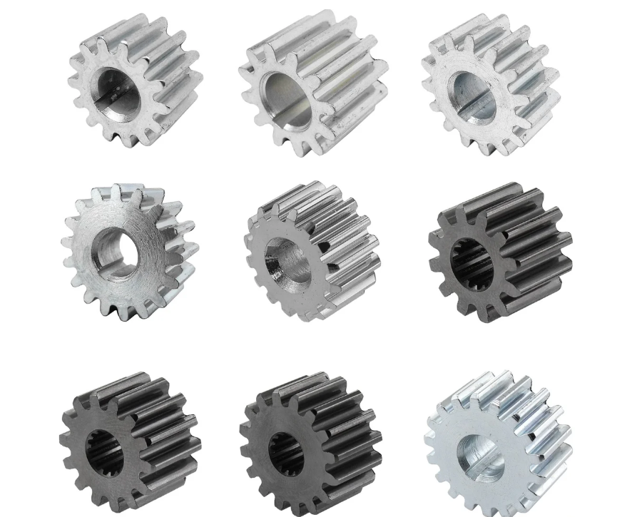
Maintainability is another basic requirement that I welcome. The gearbox must be easy to inspect and repair during normal service, and it must be easy to disassemble and reassemble during heavy maintenance. In practice, this means that the pinion gears and bearings should be accessible without unnecessary destruction of adjacent components. It also means that the housing should have inspection openings where appropriate. When a pinion gear shows unusual wear, the maintenance team should be able to identify the cause without removing the entire drive system from the vehicle.
Housing
The housing is the structural backbone of the gearbox. It must carry the gear loads, the bearing loads, the suspension loads, and the dynamic loads from the track. The standard requires that the design consider the impact of flying stones at high speed. In my experience, this is a real risk. A stone strike can initiate a crack in a housing, and a crack can propagate under repeated loading. The standard therefore directs attention to shielding, material toughness, and structural details that avoid sharp corners and stress concentrations. For the pinion gears, the housing also determines the center distance, the shaft alignment, and the bearing seat stiffness. If the housing deflects too much under load, the pinion gear mesh will be misaligned, and the tooth contact pattern will shift toward the edges of the teeth.
Pinion Gears and Gear Meshing
The standard gives particular attention to the connection between the pinion gear and the coupling. For electric multiple unit driving gearboxes, the pinion gear shaft and the coupling should preferably use a tapered interference fit. This type of connection provides high coaxiality and is convenient to assemble and disassemble. From my perspective, this is a practical requirement that improves the reliability of the pinion gear mounting. A poorly centered pinion gear will produce runout, vibration, and uneven tooth load. A tapered interference fit, when properly executed, reduces those risks.
The standard also deals with gear materials and heat treatment by referring to TB/T 2989, Rolling stock driving gearbox—Traction gears. The material requirements for pinion gears and driven gears are now aligned with that document. The standard recommends carburizing alloy steel. This is a strong signal that the industry continues to rely on case-hardened pinion gears for high load capacity and good fatigue resistance. In my own work, I treat the pinion gear material specification as a critical item. The core hardness, case depth, surface hardness, and microstructure all influence pitting resistance, bending fatigue, and scuffing resistance.
Seals
Sealing is a system property, but it is often determined by the pinion gear shaft, the housing bore, and the seal design. The standard requires dynamic seals to have a bidirectional sealing effect. Under normal operation, lubricating oil must not leak. This is more demanding than it sounds. At high speed, the seal runs against a rotating shaft, and the lubricant is thrown outward by centrifugal force. At low temperature, the seal material must remain flexible. The standard also requires water spray testing for electric multiple unit gearboxes. After the test, the lubricant must not show emulsification. I consider this requirement essential because water ingress can destroy the lubricating film on pinion gears and bearings in a very short time.
Suspension and Anti-Drop Features
For electric multiple unit driving gearboxes, the suspension device connecting the gearbox to the bogie frame should preferably use elastic nodes. These nodes isolate the gearbox from some of the high-frequency vibration from the bogie frame. I have measured shock levels above 100 g in some locations, and such levels can damage bearings and pinion gears if they are transmitted directly. The standard also requires an anti-drop safety structure. If the small end of the gearbox becomes detached, the safety structure prevents the gearbox from falling onto the track. This is a safety requirement that I regard as non-negotiable.
Accessories and Fasteners
The standard requires oil fill and drain holes, a magnetic drain plug, and a breather where needed. The magnetic plug collects fine wear particles, which can provide early warning of pinion gear or bearing distress. The oil level indicator and the upper and lower level marks make it possible to check the lubricant condition during maintenance. The standard also requires all fasteners to have anti-loosening measures and visible anti-loosening marks. This applies to all fasteners, not only to critical joints. In my view, this broad requirement is justified because a loose fastener on an accessory can still create a safety risk. Critical fasteners must be at least property class 8.8 for bolts and 8 for nuts, and they must have a corrosion-protective surface treatment.
| Basic item | Key requirement | Why it matters for pinion gears |
|---|---|---|
| Lightweight design | Total mass less than bogie or wheel-set allowance | Reduces unsprung mass and dynamic load on the pinion gear mesh |
| Maintainability | Easy inspection, disassembly, and repair | Allows pinion gear wear and backlash to be checked in service |
| Housing robustness | Consider flying stone impact | Protects gear alignment and pinion gear bearings |
| Pinion gear coupling | Tapered interference fit preferred | Improves coaxiality and reduces runout |
| Seals | Bidirectional sealing, no leakage | Keeps lubricant on pinion gears and excludes water and dust |
| Suspension | Elastic nodes and anti-drop structure | Reduces shock and prevents catastrophic separation |
| Fasteners | All have anti-loosening and marks; critical grade ≥ 8.8/8 | Maintains structural integrity of pinion gear supports |
Lubricant
The standard requires the lubricant to satisfy both the gear and bearing lubrication needs. The selection must consider the operating temperature, extreme pressure performance, demulsibility, and aging resistance. In my experience, the lubricant is one of the most powerful variables in pinion gear life. A lubricant with the wrong viscosity at low temperature can starve the bearings and cause the pinion gear to scuff during startup. A lubricant with poor demulsibility can emulsify when water enters through the seals, and the resulting mixture may not provide an adequate film. The standard’s emphasis on these properties is therefore well placed.
Performance Requirements
The performance requirements in the 2023 standard are where I see the greatest practical value. They define what the gearbox must do under environmental, thermal, dynamic, and efficiency-related conditions. I will discuss each in turn and provide tables where useful.
Environmental Adaptability
The gearbox must operate normally in high and low temperature environments. For electric multiple unit gearboxes, this means that the pinion gears, bearings, and seals must function after exposure to both temperature extremes. For locomotive wheel-set drive gearboxes, the low-temperature requirement emphasizes reliable startup. In cold conditions, the lubricant viscosity increases, and the oil may not reach the pinion gear mesh and bearings quickly enough. The standard addresses this through low-temperature testing or, when testing is not practical, through a low-temperature pour point test of the lubricant. I consider this a pragmatic compromise, but I also note that a pour point test alone does not prove that the pinion gear and bearing arrangement will receive adequate lubrication. Wherever possible, I prefer a full low-temperature running test.
Noise and Vibration
Noise and vibration are common indicators of gearbox condition. The standard uses sound pressure level or sound power level for electric multiple unit gearboxes, and sound pressure level for locomotive wheel-set drive gearboxes. Vibration is evaluated through velocity measurements. The standard requires that the root-mean-square vibration velocity should not exceed 18 mm/s. In my experience, excessive vibration often originates from pinion gear mesh errors, bearing defects, or misalignment. A vibration limit is therefore a useful screening tool. However, I also caution that a single overall velocity value may not reveal a localized pinion gear defect. For that reason, I recommend using the standard’s vibration test as a baseline and supplementing it with spectral analysis when a problem is suspected.
| Quantity | Application | Evaluation method | Limit or condition |
|---|---|---|---|
| Noise | Electric multiple unit gearbox | Sound pressure level or sound power level | Specified by test method; measured at rated speed and power |
| Noise | Locomotive wheel-set drive gearbox | Sound pressure level | No-load condition; specified speed steps and times |
| Vibration | Both applications | Vibration velocity RMS | ≤ 18 mm/s |
Temperature Limits
The standard replaces some older formula-based temperature limits with fixed values. For electric multiple unit driving gearboxes, the maximum allowable bearing temperature is 135 °C, and the maximum allowable lubricating oil temperature is 120 °C. For locomotive wheel-set drive gearboxes, the maximum allowable lubricating oil temperature is 95 °C for mineral oil or 120 °C for synthetic oil. I find these fixed limits easier to apply in design reviews and in test acceptance. They also force the designer to consider the heat generation from the pinion gear mesh, the bearing friction, and the oil churning losses. The pinion gears are often the main source of heat, especially at high speed and high load. The thermal behavior of the pinion gear mesh depends on the gear geometry, the lubricant, the surface finish, and the cooling path through the housing.
| Application | Bearing temperature limit | Oil temperature limit |
|---|---|---|
| Electric multiple unit driving gearbox | ≤ 135 °C | ≤ 120 °C |
| Locomotive wheel-set drive gearbox | Not specified as a single fixed value in the same way | ≤ 95 °C for mineral oil; ≤ 120 °C for synthetic oil |
Transmission Efficiency
Transmission efficiency is a key performance indicator. The standard now accounts for the entire gearbox rather than only the gear mesh. In the older approach, efficiency was sometimes assessed primarily from the gear pair. The new approach includes gear mesh losses, bearing losses, oil churning losses, windage losses, and seal losses. This is much more realistic for high-speed pinion gears, where churning and windage can be significant.
The efficiency is defined as:
$$ \eta = \frac{P_2}{P_1} \times 100\% = \frac{P_1 – P_V}{P_1} \times 100\% = \left(1 – \frac{P_V}{P_1}\right) \times 100\% $$
where \( \eta \) is the transmission efficiency, \( P_2 \) is the output power, \( P_1 \) is the input power, and \( P_V \) is the total power loss. The total power loss can be expressed as a sum:
$$ P_V = P_{V,\mathrm{mesh}} + P_{V,\mathrm{bearing}} + P_{V,\mathrm{churn}} + P_{V,\mathrm{windage}} + P_{V,\mathrm{seal}} $$
I find this decomposition helpful because it shows where design effort should be directed. For a high-speed gearbox, the churning and windage terms can become large if the oil level is too high or if the housing does not provide a smooth air path. For the pinion gears, the mesh loss depends on sliding velocity, load, surface finish, and lubricant. The bearing losses depend on the bearing type, preload, and speed. The seal losses depend on the seal geometry and the shaft surface speed. By reducing each term, the overall efficiency improves.
The 2023 standard requires the following efficiency values at rated power and rated speed:
| Gearbox type | Old requirement | New requirement |
|---|---|---|
| Electric multiple unit single-stage driving gearbox | ≥ 99% | ≥ 97% |
| Electric multiple unit multi-stage driving gearbox | ≥ 98% | ≥ 96% |
| Locomotive wheel-set drive gearbox | Not stated in the same unified way | ≥ 95% at rated power |
At first glance, the lower efficiency percentages may seem surprising. However, I interpret this as a more honest accounting of the entire gearbox. The older single-stage value of 99% was optimistic when all losses were considered. The new value of 97% is still a high target for a complete high-speed gearbox, and it is supported by extensive bench test data. For pinion gears, this means that the design must minimize mesh loss without compromising load capacity. That balance is not trivial. A very smooth pinion gear surface reduces friction, but it must still have the correct case depth and residual stress to resist pitting and bending fatigue.
Static Strength
The standard requires static strength verification for the housing and the suspension rod or C-shaped bracket. The stress in critical areas must not exceed the material yield limit. In my view, this is especially important for the pinion gear support structure. If the housing yields under a short-circuit torque or a protection torque, the pinion gear alignment will be lost, and the gearbox may fail. The static strength test is therefore a check on the structural integrity of the entire load path from the traction motor to the wheel set.
Sealing and Water Resistance
Electric multiple unit driving gearboxes must undergo a water spray test. After the test, the lubricant must not emulsify. This requirement addresses a real operating condition. In rain, snow, or wet conditions, water can reach the seals. If the seals are not effective, water will enter the gearbox and mix with the oil. The resulting emulsion may reduce lubricant film thickness and cause pinion gear scuffing or bearing corrosion. I consider the water spray test a valuable addition because it directly validates the whole sealing system, including the pinion gear shaft seal, the housing joints, and the breather arrangement.
Casting Defect Inspection
The standard requires non-destructive inspection of cast housings. For cast aluminum alloy housings, radiographic inspection must meet the requirements of TB/T 3409—2021. For ductile iron housings, the defect grades must meet the specified acceptance levels. Magnetic particle inspection is also required for ductile iron housings according to the relevant magnetic particle testing standards. The acceptance criteria for ductile iron housings are summarized in the following table.
| Housing wall thickness \( t \) (mm) | Linear or dotted-linear indication: single length (mm) | Linear or dotted-linear indication: cumulative length (mm) | Non-linear indication: single length (mm) | Non-linear indication: total area (mm²) |
|---|---|---|---|---|
| \( t \le 16 \) | 6 | 10 | 6 | 70 |
| \( 16 < t \le 50 \) | 9 | 18 | 6 | 70 |
| \( 50 < t \) | 15 | 30 | 6 | 70 |
I use this table during supplier audits. It gives clear numerical limits for acceptance and rejection. For pinion gear housings, the area around the bearing seats and the gear mesh region is especially critical. A defect in that region can reduce local stiffness, alter the contact pattern, and accelerate pinion gear wear.
Main Component Requirements
The 2023 standard includes detailed requirements for the housing, the gears, the bearings, and the assembly process. I will summarize the most important points and add my own observations from field experience.
Housing
The housing should preferably be made of cast aluminum alloy or ductile iron. The standard specifies mechanical properties for separately cast test pieces and for test pieces taken from the actual casting. For cast aluminum alloy housings, the mechanical properties from body samples must meet the requirements for class B castings in TB/T 3409—2021. For ductile iron housings, the body sample properties must meet TB/T 1465. Surface quality must also meet the relevant standard. In addition, threaded holes in cast aluminum alloy housings should be fitted with wire thread inserts. This protects the threads and allows higher clamping loads. The housing should also have an inspection opening where practical, and it must have lifting lugs or ring screw holes for safe handling.
From the perspective of pinion gear performance, the housing is not a passive container. Its stiffness determines the misalignment of the pinion gear under load. Its thermal expansion affects the backlash. Its damping characteristics influence vibration. Its oil passages determine how much lubricant reaches the pinion gear mesh and the bearings. I therefore treat the housing as an active part of the transmission system, not just a cover.
Gears and Pinion Gears
The standard requires gear materials to comply with TB/T 2989. The common material grades and their requirements are given in that standard, and carburizing alloy steel is recommended. The standard also requires calculation or verification of contact load capacity, bending load capacity, scuffing load capacity, and static strength. These checks are essential for pinion gears because they operate at high speed and high load. The contact load capacity relates to pitting resistance. The bending load capacity relates to tooth root fatigue. The scuffing load capacity relates to the risk of adhesive wear at high sliding velocities. The static strength check ensures that the pinion gear can survive a short-circuit torque or another extreme event without permanent deformation.
Gear backlash is another critical requirement. The standard requires the backlash to meet the design value and to be measured according to the relevant inspection code for cylindrical gears. Backlash affects lubrication, noise, and load distribution. If the backlash is too small, the pinion gear may bind or overheat. If it is too large, the impact load at reversal may increase, and the contact pattern may become unfavorable. I have seen cases where a small backlash error caused a distinct whine at high speed and a measurable increase in bearing temperature.
| Check for pinion gears and mating gears | Purpose | Typical method |
|---|---|---|
| Contact load capacity | Resist surface pitting | Calculation according to gear load capacity standards |
| Bending load capacity | Resist tooth root fatigue | Calculation according to gear load capacity standards |
| Scuffing load capacity | Resist adhesive wear at high speed | Calculation according to gear load capacity standards |
| Static strength | Resist extreme torque without yielding | Calculation or test |
| Backlash | Ensure proper lubrication and smooth meshing | Measurement according to gear inspection code |
The standard also deletes the requirement for residual unbalance of traction gears. This is a notable change. In my understanding, modern pinion gears are forged and fully precision machined, so material uniformity is much better than in the past. The need for a separate residual unbalance check has therefore diminished. I agree with this change for most applications, but I still recommend balancing verification for very high-speed pinion gears or for gears with unusual geometry.
Bearings
Bearings are the interface between the rotating pinion gears and the fixed housing. The standard requires bearing life calculation with a defined mass range. For the bearing at the pinion gear, the calculation mass includes the pinion gear and all parts mounted on the pinion gear shaft. For the bearing at the driven gear, the calculation mass includes the gearbox mass except the driven gear and all parts mounted on the output shaft, excluding the large bearing. This is a practical rule that avoids underestimating or overestimating the inertia and load. The standard also requires the bearing clearance to meet the assembly specification.
| Bearing location | Mass range for life calculation |
|---|---|
| Pinion gear bearing | Pinion gear and all parts mounted on the pinion gear |
| Driven gear bearing | Gearbox mass excluding the driven gear and all parts mounted on the output shaft, excluding the large bearing |
In my experience, bearing life is often the limiting factor for high-speed pinion gears. The bearing must handle radial and axial loads, high speed, and temperature. The lubricant must reach the bearing under all operating conditions. The clearance must be correct after assembly. If the clearance is too small, the bearing may overheat. If it is too large, the pinion gear may lose alignment. The standard’s emphasis on bearing life and clearance is therefore well founded.
Assembly and Disassembly
The standard requires that all components be inspected and qualified before assembly. The driven gear, bearings, and wheel-set parts are assembled by thermal shrink fitting or press fitting. Static sealing surfaces must have a sealing measure, such as sealant or a gasket. During assembly, the gear backlash, bearing clearance, and key component serial numbers must be recorded. After testing, the gearbox must be dismantled for inspection. The inspection items include the magnetic drain plug, the pinion gear tooth surfaces, the bearings, the other components, and the lubricant. The magnetic plug must not have sheet-like or block-like particles. The pinion gear tooth surfaces must not have pitting, spalling, adhesion, or cracks. The bearings must rotate normally and must not have abnormal wear, scratching, or spalling. The lubricant must not change significantly in performance and must not emulsify.
I consider the post-test dismantling inspection to be one of the most valuable requirements in the standard. It provides direct evidence of the internal condition of the gearbox. A bench test can show temperature, vibration, and efficiency, but only a dismantling inspection can reveal the true condition of the pinion gear teeth and the bearing races. I have used this inspection to identify manufacturing issues such as inadequate case depth, poor grinding burns, and incorrect bearing preload.
Test Methods
The 2023 standard defines a comprehensive set of test methods. I will organize them into categories and provide tables to show the test matrix for electric multiple unit and locomotive applications.
Run-In Test
The run-in test is performed after assembly. The gearbox is accelerated from zero to each speed level in steps. Each speed level is held for a period before advancing to the next level. The maximum operating speed is held for at least 5 minutes. The test is performed in both directions of rotation. The purpose is to check lubrication, sealing, bearing temperature rise, and gear meshing. For pinion gears, the run-in test helps to distribute the lubricant and to reveal any initial meshing problems. I always pay close attention to the pinion gear mesh during this test because it is the first opportunity to observe the complete system under rotation.
Loaded Tests
Loaded tests simulate the actual operating conditions. For electric multiple unit driving gearboxes, the standard requires rated speed loaded tests, maximum speed loaded tests, maximum operating speed loaded tests, maximum starting torque loaded tests, and durability tests. For locomotive wheel-set drive gearboxes, the standard requires rated speed loaded tests, maximum operating speed loaded tests, temperature rise tests, overload tests, and durability tests. During locomotive tests, the axle load must be simulated. The loading is applied gradually in steps of 25%, 50%, 75%, and 100% of the corresponding torque. The tests are performed in both directions.
| Test | Electric multiple unit gearbox | Locomotive wheel-set drive gearbox |
|---|---|---|
| Rated speed loaded test | Required | Required |
| Maximum speed loaded test | Required | Not the same designation |
| Maximum operating speed loaded test | Required | Required as maximum operating speed loaded test |
| Maximum starting torque loaded test | Required | Not explicitly the same |
| Temperature rise test | Covered by loaded tests | Required |
| Overload test | Deleted as a separate test | Required |
| Durability test | Required | Required |
High and Low Temperature Tests
High and low temperature tests check the gearbox under environmental extremes. For electric multiple unit gearboxes, the low-temperature test runs at 90% or more of the maximum operating speed for at least 30 minutes. The high-temperature test runs at the maximum operating speed for at least 1 hour. For locomotive wheel-set drive gearboxes, the low-temperature test accelerates to the maximum speed according to the locomotive design acceleration and runs for at least 30 minutes. If low-temperature testing is not possible, a low-temperature pour point test of the lubricant may be used instead. I have already explained why I prefer a full running test when it can be done. The behavior of pinion gears at low temperature depends on the lubricant reaching the mesh quickly. A pour point test does not prove that the lubrication system will deliver oil to the pinion gear under load.
| Test | Electric multiple unit gearbox | Locomotive wheel-set drive gearbox |
|---|---|---|
| Low temperature | ≥ 90% maximum operating speed for ≥ 30 min | Accelerate to maximum speed, run ≥ 30 min; pour point test may substitute |
| High temperature | Maximum operating speed for ≥ 1 h | Not specified in the same way |
Vibration, Noise, and Efficiency Tests
Vibration and noise tests are performed at rated speed and rated power for electric multiple unit gearboxes. For locomotive gearboxes, vibration is measured at rated speed and no-load or light-load conditions. Noise is measured at no-load conditions at different speeds. Efficiency is measured at rated speed and different torque conditions for locomotive gearboxes, and at rated speed and rated power for electric multiple unit gearboxes. The standard refers to GB/T 14231 for efficiency measurement and GB/T 6075.1—2012 for vibration measurement. The noise test for locomotive wheel-set drive gearboxes is summarized in the following table.
| Locomotive speed (new wheel) | Running time (min) |
|---|---|
| 0–20 km/h | 3 |
| 50% of maximum operating speed | 10 |
| 75% of maximum operating speed | 30 |
| Construction speed | 3 |
| Construction speed to 0 | Natural deceleration |
I find the noise test conditions important because they exclude external excitations such as track irregularities, car body mass, and traction motor noise. This makes it possible to evaluate the gearbox itself, including the pinion gear mesh, the bearings, and the oil churning. When I review a noise test report, I look for tonal components that may indicate a pinion gear mesh frequency problem or a bearing defect frequency.
Other Tests
The standard also includes several other tests. Electric multiple unit gearboxes must undergo a water spray test and a static strength test. Locomotive wheel-set drive gearboxes must undergo a sealing test, a no-load test, an oil level test, an overspeed test, and a tilt test. The tilt test is performed at different speeds, oil levels, and tilt angles to verify stable operation. In the 2023 standard, the tilt test method is aligned with the relevant reliability verification test method for AC drive locomotive wheel-set drive systems.
| Test | Application | Purpose |
|---|---|---|
| Water spray test | Electric multiple unit gearbox | Verify sealing and no oil emulsification |
| Static strength test | Electric multiple unit gearbox | Verify housing and suspension rod strength |
| Sealing test | Locomotive wheel-set drive gearbox | Verify housing sealing |
| No-load test | Locomotive wheel-set drive gearbox | Check operation without load |
| Oil level test | Locomotive wheel-set drive gearbox | Check operation at different oil levels |
| Overspeed test | Locomotive wheel-set drive gearbox | Check operation above maximum speed |
| Tilt test | Locomotive wheel-set drive gearbox | Check sealing and operation at tilt angles |
The standard deletes several older tests for electric multiple unit gearboxes, including the separate no-load test, the separate overload test, the tilt test, and the gear material contact fatigue test. It also deletes the contact pattern measurement for gears. These deletions are justified by the fact that the remaining tests already cover the deleted requirements. For example, the run-in test and the high-temperature test cover the no-load condition. The maximum starting torque test covers the overload condition. The loaded tests cover the sealing condition that the tilt test was intended to check. The contact fatigue performance is covered by the contact and bending load capacity calculations. I agree with these deletions because they simplify the test program without reducing the actual verification coverage.
Inspection Rules
The inspection rules in the 2023 standard are divided into factory inspection and type inspection. I will summarize both and provide the conditions that require a type inspection.
Factory Inspection
Factory inspection is performed on every gearbox before delivery. The standard aligns the factory inspection items with the test methods. It deletes some items that are no longer required, such as gear dynamic balance, gear contact pattern, and housing surface quality for electric multiple unit gearboxes. For manufacturing models where the main builder purchases housings, gears, and other components and assembles the gearbox, the standard allows some factory inspection items to be covered by component manufacturer test reports. These items include housing non-destructive testing, gear pair backlash measurement, bearing clearance measurement, and, for locomotive gearboxes, sealing tests and mechanical property tests. I find this a practical accommodation for modern supply chains. It recognizes that the component manufacturer may have better test equipment and more detailed knowledge of the component.
| Factory inspection item | Notes |
|---|---|
| Housing non-destructive testing | May be provided by component manufacturer test report |
| Gear pair backlash measurement | May be provided by component manufacturer test report |
| Bearing clearance measurement | May be provided by component manufacturer test report |
| Sealing test for locomotive gearbox | May be provided by component manufacturer test report |
| Mechanical property test for locomotive gearbox | May be provided by component manufacturer test report |
Type Inspection
Type inspection is a comprehensive verification of the gearbox design. It includes the tests described earlier, such as run-in, loaded tests, high and low temperature tests, vibration, noise, efficiency, and the other application-specific tests. The 2023 standard deletes the no-load test, overload test, tilt test, overspeed test, and gear material contact fatigue test for electric multiple unit gearboxes. It adds the water spray test and the high-temperature test. It also expands the low-temperature test range. For locomotive wheel-set drive gearboxes, the standard adjusts the run-in test mode, requires at least 5 minutes at the maximum operating speed, adds tilt operating conditions, allows a low-temperature pour point test as a substitute when low-temperature starting tests are not possible, and corrects the noise test conditions, measurement points, and ambient noise requirements.
The conditions requiring a type inspection are unified for both electric multiple unit gearboxes and locomotive wheel-set drive gearboxes. A type inspection is required in the following situations:
- When a new product is being type-approved.
- When the product structure, process, or material undergoes a significant change.
- When production is transferred to a different site.
- When production resumes after a shutdown of more than 2 years.
- When production has continued for more than 5 years.
I consider the 5-year periodic type inspection requirement particularly important. It ensures that a design that has been in production for a long time is re-evaluated against the current standard and the current manufacturing capability. For pinion gears, this periodic review can reveal whether the original material, heat treatment, or grinding process still meets the requirements after years of supplier changes and process adjustments.
Equations for Design and Verification
To help designers apply the standard, I have collected several equations that are commonly used in the design and verification of driving gearboxes and pinion gears. These equations are consistent with the principles in the standard, even when the standard refers to other documents for the detailed calculation method.
Transmission Efficiency
The overall efficiency is the ratio of output power to input power:
$$ \eta = \frac{P_2}{P_1} \times 100\% $$
The power loss is the difference between input and output power:
$$ P_V = P_1 – P_2 $$
Expressed as a fraction of input power:
$$ \frac{P_V}{P_1} = 1 – \eta $$
The total loss can be decomposed into mesh, bearing, churning, windage, and seal losses:
$$ P_V = P_{V,\mathrm{mesh}} + P_{V,\mathrm{bearing}} + P_{V,\mathrm{churn}} + P_{V,\mathrm{windage}} + P_{V,\mathrm{seal}} $$
For a pinion gear mesh, the mesh loss depends on the friction coefficient, the sliding velocity, and the normal force. A simplified representation is:
$$ P_{V,\mathrm{mesh}} = \mu_{\mathrm{mesh}} F_n v_s $$
where \( \mu_{\mathrm{mesh}} \) is the equivalent mesh friction coefficient, \( F_n \) is the normal tooth force, and \( v_s \) is the sliding velocity at the mesh point.
Bearing Life
The basic rating life of a bearing is given by:
$$ L_{10} = \left(\frac{C}{P}\right)^p \times 10^6 \text{ revolutions} $$
where \( L_{10} \) is the basic rating life, \( C \) is the basic dynamic load rating, \( P \) is the equivalent dynamic bearing load, and \( p \) is the life exponent (3 for ball bearings, 10/3 for roller bearings).
The modified rating life is:
$$ L_{nm} = a_1 a_{ISO} L_{10} $$
where \( a_1 \) is the life modification factor for reliability and \( a_{ISO} \) is the life modification factor for lubrication, contamination, and fatigue load limit.
For the pinion gear bearing, the equivalent dynamic load is often a combination of radial and axial loads:
$$ P = X F_r + Y F_a $$
where \( F_r \) is the radial load, \( F_a \) is the axial load, and \( X \) and \( Y \) are bearing-specific factors.
Gear Load Capacity
The contact stress in a pinion gear mesh can be estimated by:
$$ \sigma_H = Z_H Z_E Z_\varepsilon Z_\beta \sqrt{\frac{F_t}{d_1 b} \frac{u + 1}{u} K_A K_V K_{H\beta} K_{H\alpha}} $$
where \( \sigma_H \) is the contact stress, \( Z_H \) is the zone factor, \( Z_E \) is the elasticity factor, \( Z_\varepsilon \) is the contact ratio factor, \( Z_\beta \) is the helix angle factor, \( F_t \) is the tangential force, \( d_1 \) is the pinion gear reference diameter, \( b \) is the face width, \( u \) is the gear ratio, and the \( K \) factors are the application, dynamic, face load, and transverse load factors.
The tooth root bending stress can be estimated by:
$$ \sigma_F = \frac{F_t}{b m_n} Y_F Y_S Y_\beta K_A K_V K_{F\beta} K_{F\alpha} $$
where \( \sigma_F \) is the bending stress, \( m_n \) is the normal module, \( Y_F \) is the form factor, \( Y_S \) is the stress correction factor, \( Y_\beta \) is the helix angle factor, and the \( K \) factors are the corresponding load factors.
These equations are not a substitute for the detailed calculation methods referenced by the standard, but they illustrate the physical quantities that must be controlled. For pinion gears, the most important variables are the tangential force, the face width, the module, the gear ratio, and the load distribution factors. A design that reduces the tangential force or increases the face width can reduce contact stress, but it may also increase mass and churning loss. The standard’s efficiency and temperature requirements therefore interact with the load capacity requirements.
Backlash and Thermal Effects
Backlash is affected by manufacturing tolerances and thermal expansion. A simple estimate of the change in backlash due to temperature is:
$$ \Delta j = j_0 \alpha \Delta T $$
where \( \Delta j \) is the change in backlash, \( j_0 \) is the initial backlash, \( \alpha \) is the coefficient of thermal expansion, and \( \Delta T \) is the temperature change. In a gearbox, the housing, the pinion gear, and the driven gear may have different coefficients of thermal expansion. This is especially important for aluminum alloy housings with steel pinion gears. The standard’s temperature limits and material requirements help to ensure that the backlash remains within acceptable limits over the operating temperature range.
Lubricant Viscosity
The viscosity of the lubricant changes strongly with temperature. A common empirical relationship is the ASTM D341 equation:
$$ \log_{10}(\log_{10}(\nu + 0.7)) = A – B \log_{10}(T) $$
where \( \nu \) is the kinematic viscosity, \( T \) is the absolute temperature, and \( A \) and \( B \) are fluid-specific constants. This equation is useful for checking whether the lubricant will provide adequate film thickness at the low-temperature startup condition and whether it will maintain sufficient viscosity at the high-temperature operating condition. For pinion gears, the low-temperature viscosity affects the risk of starvation, while the high-temperature viscosity affects the risk of scuffing and wear.
Practical Implications for Pinion Gears and Gearbox Design
After reviewing the 2023 standard in detail, I would like to summarize the practical implications for pinion gears and gearbox design. These are the points I emphasize in design reviews and supplier discussions.
First, the pinion gear cannot be designed in isolation. Its material, heat treatment, geometry, and surface finish must be considered together with the housing stiffness, the bearing arrangement, the lubricant, and the sealing system. The standard’s system-level approach reflects this reality. When I see a pinion gear design that meets the load capacity calculation but ignores the housing deflection or the bearing clearance, I know that the actual service life may be much shorter than predicted.
Second, the efficiency requirement is now more realistic but also more demanding in terms of system optimization. The 97% target for a single-stage electric multiple unit gearbox includes all losses. To meet it, the designer must minimize pinion gear mesh loss, bearing loss, churning loss, windage loss, and seal loss. This requires attention to oil level, oil flow, surface finish, bearing selection, and seal design. I have found that the churning loss can be reduced by lowering the oil level within safe limits, but this must be balanced against the risk of insufficient lubrication at the pinion gear mesh and bearings.
Third, the temperature limits are fixed and easy to apply. The pinion gear mesh is often the hottest point in the gearbox. To keep the bearing temperature below 135 °C and the oil temperature below 120 °C, the designer must control the heat generation and ensure adequate heat dissipation. This may require oil cooling, housing fins, or a careful thermal layout. The high-temperature test at maximum operating speed for at least 1 hour is a good validation of the thermal design.
Fourth, the sealing requirements are more stringent. The water spray test and the no-emulsification requirement mean that the pinion gear shaft seal, the housing joints, and the breather must work together. I have seen gearboxes with excellent gear and bearing design fail because water entered through a poorly designed breather. The standard’s sealing requirements help to prevent such failures.
Fifth, the inspection rules place more responsibility on the component supply chain. The standard allows component manufacturer test reports to cover certain factory inspection items. This is efficient, but it also means that the main builder must audit the component manufacturer’s quality system. For pinion gears, the critical characteristics are material chemistry, case depth, surface hardness, core hardness, microstructure, tooth profile, lead accuracy, surface finish, and backlash. I recommend that the main builder verify these characteristics through a combination of supplier audits, incoming inspection, and periodic type testing.
Sixth, the type inspection conditions require periodic revalidation. The 5-year rule ensures that a pinion gear design that has been in production for years is rechecked against the current standard. This is important because manufacturing processes can drift over time. A pinion gear that was once at the upper limit of case depth may gradually move toward the lower limit, or a grinding process may introduce a different residual stress pattern. Periodic type inspection catches these trends before they become field problems.
Comparison of Old and New Requirements
To make the changes easier to see, I have prepared a comparison table of the most significant old and new requirements.
| Item | Old approach | New approach |
|---|---|---|
| Ambient temperature | Separate values; locomotive up to +50 °C | Unified -40 °C to +40 °C, with special electric multiple unit condition |
| Fastener anti-loosening | Important joints only | All fasteners |
| Bearing temperature | Formula-based | ≤ 135 °C for electric multiple unit gearbox |
| Oil temperature | Formula-based | ≤ 120 °C for electric multiple unit; ≤ 95 °C mineral or ≤ 120 °C synthetic for locomotive |
| Transmission efficiency | Single-stage ≥ 99%, multi-stage ≥ 98% | Single-stage ≥ 97%, multi-stage ≥ 96%, locomotive ≥ 95% |
| Housing mechanical properties | Less explicit | Separate requirements for attached or separately cast test pieces and body samples |
| Pinion gear material | Broad requirement | Direct reference to TB/T 2989; carburizing alloy steel recommended |
| Fastener design | Specific anti-loosening and engagement length rules | Comply with TB/T 3246 |
| Weight | Not a unified requirement | Lightweight design; mass below bogie or wheel-set allowance |
| Lubricant | General requirement | Must satisfy gear and bearing; consider temperature, EP, demulsibility, aging |
| Bearing life calculation | Less specific mass range | Defined mass ranges for pinion gear and driven gear bearings |
| Aluminum thread torque | Assumed 4.8 grade bolt torque | Deleted; wire thread inserts or steel inserts used |
| Pinion gear residual unbalance | Required | Deleted |
| Vibration test | Light-load rated speed | Rated speed and rated power, forward and reverse |
| Noise test | Various conditions | No-load for locomotive; corrected conditions and measurement points |
| Tilt test for electric multiple unit | Required | Deleted |
| Water spray test | Not required | Required for electric multiple unit |
| High-temperature test | Not required | Required for electric multiple unit |
| Contact pattern measurement | Required | Deleted |
| Gear material contact fatigue test | Required | Deleted |
This table shows that the 2023 standard is not simply more stringent or less stringent. It is more realistic, more unified, and more focused on system performance. The changes to pinion gear residual unbalance and contact pattern measurement reflect improvements in manufacturing precision. The changes to efficiency and temperature reflect a better understanding of actual losses and thermal behavior. The changes to sealing and water spray reflect the real operating environment of high-speed trains.
Conclusion
In my assessment, TB/T 3134—2023 is a significant step forward for rolling stock driving gearboxes. It merges two distinct standards into one coherent document, updates the technical requirements to match modern materials and manufacturing methods, and introduces test methods that better reflect actual service conditions. The standard places the pinion gears, the housing, the bearings, the seals, and the lubricant into a single system-level framework. This is exactly the right approach, because the pinion gear is only as reliable as the system that surrounds it.
For designers, the standard provides clear targets for efficiency, temperature, vibration, noise, and sealing. For manufacturers, it provides clear rules for materials, heat treatment, inspection, and testing. For operators and maintainers, it provides a basis for condition monitoring and overhaul decisions. The repeated emphasis on pinion gears in this article reflects their central role in the gearbox. Every requirement—whether it concerns housing stiffness, bearing clearance, lubricant selection, or test validation—ultimately affects the pinion gear mesh and its ability to transmit torque reliably over millions of kilometers.
As I look to the future, I expect further developments in high-speed pinion gears, lightweight materials, and intelligent condition monitoring. The 2023 standard provides a solid foundation for those developments. It is a document that I will continue to use in design reviews, supplier qualifications, and test program planning. When applied carefully, it will help to ensure that driving gearboxes and their pinion gears meet the demanding requirements of modern railway operation.