
In my work on locomotive bogie drive systems, I have focused on one of the most critical components: the driving pinion gear shaft. These pinion gears transmit the motor torque to the axle gearbox, and their bearing seats must maintain an exact interference fit with the bearing inner rings. When a workshop discovered that several pinion gear shafts had bearing seats with increased dimensions after service, I initiated a systematic study covering heat treatment simulation, residual austenite transformation, interference fit evaluation, and finite element post-processing automation. The following sections present my methods, calculations, and conclusions in detail.
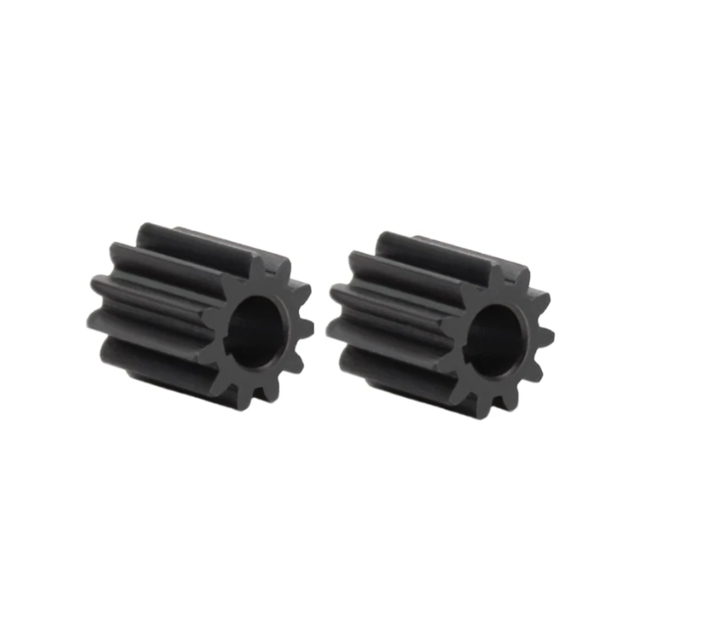
The pinion gears used in these locomotives are manufactured from 17Cr2Ni2Mo, a low-carbon alloy steel with high surface hardness and excellent core toughness. The nominal chemical composition is summarized in Table 1. Because the bearing seats are finish-machined before heat treatment, any dimensional change during quenching and tempering directly affects the final interference fit. Therefore, I began by reproducing the entire industrial heat treatment route in a coupled thermal–metallurgical finite element framework.
| Element | C | Cu | Mn | S | P | Cr | Ni | Mo | Si |
|---|---|---|---|---|---|---|---|---|---|
| Mass fraction (%) | 0.17 | 0.30 | 0.45 | 0.0035 | 0.0035 | 1.65 | 1.55 | 0.30 | 0.035 |
The heat treatment cycle for these pinion gears consists of three main stages: austenitizing at approximately 820 °C for about two hours, oil quenching with the oil temperature kept below 60 °C, and two identical low-temperature tempering treatments at about 180 °C for two hours followed by air cooling. To capture the evolution of temperature, stress, and phase fractions, I built an axisymmetric finite element model of the pinion gear shaft. The end teeth, main teeth, and threads were simplified, while the two bearing seats and the central shaft body were retained with high mesh density. The mesh consisted of 16,332 linear hexahedral elements and 17,695 nodes. A transient temperature–displacement coupled analysis was used for quenching, and the workpiece was fully constrained at the non-end-tooth face while gravity was included.
The thermal boundary condition between the pinion gears and the quenching oil was described by a temperature-dependent heat transfer coefficient. I used published data for 17Cr2Ni2Mo and quenching oil, which I interpolated into the finite element solver. The governing heat conduction equation solved in the transient analysis is:
$$ \rho c_p \frac{\partial T}{\partial t} = \nabla \cdot (k \nabla T) + \dot{q} $$
where \(\rho\) is density, \(c_p\) is specific heat capacity, \(T\) is temperature, \(t\) is time, \(k\) is thermal conductivity, and \(\dot{q}\) is the internal heat generation rate. For the mechanical part, the total strain was decomposed into thermal, elastic, plastic, and transformation-induced components. I defined the temperature-dependent material properties shown in Table 2. These properties were critical because the thermal stress and phase transformation kinetics depend strongly on the instantaneous temperature and cooling rate.
| Property | 20 °C | 200 °C | 400 °C | 600 °C | 800 °C |
|---|---|---|---|---|---|
| Thermal conductivity \(k\) (W/m·K) | 42 | 40 | 36 | 31 | 25 |
| Young’s modulus \(E\) (GPa) | 210 | 200 | 185 | 165 | 140 |
| Poisson’s ratio \(\nu\) | 0.30 | 0.30 | 0.31 | 0.32 | 0.33 |
| Specific heat \(c_p\) (J/kg·K) | 460 | 510 | 570 | 650 | 740 |
| Yield strength \(\sigma_y\) (MPa) | 850 | 780 | 650 | 450 | 220 |
| Thermal expansion coefficient \(\alpha\) (10⁻⁶/K) | 11.5 | 12.0 | 12.8 | 13.5 | 14.2 |
During quenching, the surface temperature of the bearing seats dropped from 820 °C to below 100 °C within approximately 200 seconds, while the core cooled more slowly. I extracted the temperature histories at the end-tooth-side bearing seat and the non-end-tooth-side bearing seat. By superimposing these cooling curves on the continuous cooling transformation diagram of 17Cr2Ni2Mo, I could identify the phase transformation sequence. The cooling path first entered the bainite region, producing a fraction of bainite. Then it crossed the martensite start temperature \(M_s\), and the remaining austenite partially transformed to martensite. However, even when the temperature fell below the martensite finish temperature \(M_f\), a small amount of austenite remained untransformed. This retained austenite is the key to the dimensional instability observed in the pinion gears.
The thermal stress distribution after quenching showed a strong asymmetry. The non-end-tooth-side bearing seat experienced a maximum thermal stress of about 800 MPa, while the end-tooth-side bearing seat had a much lower stress, with a maximum of about 350 MPa near the root and only about 70 MPa in other regions. The first tempering step reduced the non-end-tooth-side stress from about 680 MPa to about 590 MPa, but the end-tooth-side stress changed by only about 5 MPa. The second tempering step produced an even smaller reduction. After the complete heat treatment, residual thermal stress remained mainly on the non-end-tooth side, while the end-tooth side showed very little residual stress. This distribution did not match the observed dimensional changes, because both bearing seats expanded. Therefore, I ruled out residual thermal stress release as the primary cause of the bearing seat growth.
Based on the engineering inverse problem approach, I combined the metallurgical analysis with surface observations. The bearing seats exhibited non-uniform swelling with a magnitude between 0.01 mm and 0.12 mm. The austenite phase has a face-centered cubic structure with a density of 0.74, while martensite has a body-centered cubic structure with a density of 0.68. The atomic radius in the face-centered cubic cell is \(\sqrt{2}a/4\), and the atomic volume is \(\sqrt{2}\pi a^3/6\). In the body-centered cubic cell, the atomic radius is \(\sqrt{3}a/4\). Because the body-centered cubic structure requires more space per atom, the transformation from austenite to martensite or bainite inevitably increases the volume. The volume expansion can be estimated as:
$$ \frac{\Delta V}{V} = \frac{V_{\text{bcc}} – V_{\text{fcc}}}{V_{\text{fcc}}} \approx 0.03 \text{ to } 0.05 $$
Moreover, the martensite or bainite transformation in the surface layer is constrained in three directions but free in the outward normal direction. This leads to the well-known surface relief or tent-like uplift, which produces non-uniform swelling rather than a uniform radial expansion. The transformation does not occur simultaneously; the first-formed plates or laths restrict the later ones. As a result, the final deformation is a superposition of volume expansion and orientation-dependent surface relief. For the pinion gears, this explains why the bearing seats grow irregularly and why the roundness and cylindricity tolerances are lost.
To reduce the retained austenite content and stabilize the dimensions of pinion gears, I evaluated four process improvements. Table 3 summarizes their mechanisms, advantages, and limitations.
| Method | Mechanism | Typical parameters | Advantages | Limitations |
|---|---|---|---|---|
| Magnetic deep cryogenic treatment | Low temperature reduces martensite volume and frees space; magnetic field destabilizes austenite | −190 °C, 1 T, 3–4 h | Very effective for retained austenite reduction; improves dimensional stability | High equipment cost; local treatment needed for pinion gears |
| Local tempering of bearing seats | Carbide precipitation relieves carbon supersaturation and provides space for austenite transformation | 200–300 °C, 2 h | Simple; compatible with existing lines | May reduce hardness if applied to gear teeth; local heating required |
| Bainite isothermal quenching | Avoids large martensite fraction; bainite forms isothermally above \(M_s\) | Two-step: first just above \(M_s\), then higher | Reduces retained austenite from source; good toughness | Requires salt bath or controlled furnace; process window narrow |
| Reduced carbon potential during carburizing | Lower carbon content lowers austenite stability | Carbon potential reduced by 0.1–0.2% | Easy to implement | May reduce surface hardness and wear resistance of pinion gears |
For the magnetic deep cryogenic treatment, the pinion gears are cooled to about −190 °C in liquid nitrogen or a cryogenic chamber while a magnetic field of about 1 T is applied. The low temperature contracts the martensite, reducing the compressive constraint on the remaining austenite. The magnetic field provides an additional driving force because martensite is ferromagnetic while austenite is paramagnetic. I found that this combination is particularly effective for the bearing seat regions, where the wall thickness is moderate and the cooling rate during quenching is relatively high. However, because the gear teeth benefit from a small amount of retained austenite for toughness and contact fatigue resistance, the treatment should be localized to the bearing seats.
Local tempering is another practical route. When the pinion gears are reheated to 200–300 °C, fine carbides precipitate from the martensite, reducing its tetragonality and volume. This creates space for the retained austenite to transform. The optimum temperature depends on the steel grade and the desired hardness. For 17Cr2Ni2Mo, I recommend a local induction tempering at 230 °C for two hours, followed by air cooling. This treatment should be applied only to the bearing seat areas, and the gear teeth should be shielded or cooled to avoid softening.
Bainite isothermal quenching replaces the conventional martensitic quench. In a two-step process, the pinion gears are first held just above the martensite start temperature to form 50–70% bainite, and then the temperature is raised to complete the transformation. Because bainite forms at a higher temperature than martensite, the volume change is smaller and the retained austenite content is lower. The resulting microstructure has good dimensional stability and toughness. The main challenge is that the process requires a salt bath or a fluidized bed with precise temperature control. For large pinion gears, the cooling rate must be uniform to avoid distortion.
Reducing the carbon potential during carburizing is the simplest metallurgical lever. Carbon is the strongest austenite stabilizer. When the carbon content is reduced from 0.8% to 0.6% in the case, the martensite start temperature increases and the amount of retained austenite decreases. However, the surface hardness and wear resistance of the pinion gears may be compromised. Therefore, this method should be combined with a slight increase in case depth or a change in alloy content to maintain the required contact fatigue life.
After establishing the root cause, I turned to the second objective: determining whether a pinion gear shaft with an already enlarged bearing seat can be reused. The reuse decision must ensure that the new bearing inner ring will not be overloaded and that the bearing will operate with sufficient internal clearance. I established four criteria based on bearing handbook recommendations: maximum effective interference, maximum surface pressure on the bearing inner ring, maximum stress in the bearing inner ring, and minimum effective operating clearance. These criteria are summarized in Table 4.
| Criterion | Symbol | Limit | Physical meaning |
|---|---|---|---|
| Maximum effective interference | \(I_{\max}\) | 0.076–0.0985 mm depending on bearing type | Prevents excessive hoop stress and inner ring fracture |
| Maximum surface pressure | \(p_{\max}\) | 23–25 MPa | Limits contact pressure at the fit surface |
| Maximum stress in inner ring | \(\sigma_{t,\max}\) | 110–120 MPa | Keeps the inner ring in the elastic range |
| Minimum effective clearance | \(\Delta_{\min}\) | 0.0309–0.0777 mm | Ensures rolling elements do not jam |
To compute the effective interference, I used the thick-walled cylinder theory. For a ring under internal pressure \(p_i\) and external pressure \(p_0\), the radial and tangential stresses are:
$$ \sigma_r = -p_i \frac{(R_0/R)^2 – 1}{(R_0/R_i)^2 – 1} – p_0 \frac{1 – (R_i/R)^2}{1 – (R_i/R_0)^2} $$
$$ \sigma_\theta = p_i \frac{(R_0/R)^2 + 1}{(R_0/R_i)^2 – 1} – p_0 \frac{1 + (R_i/R)^2}{1 – (R_i/R_0)^2} $$
where \(R_i\) is the inner radius and \(R_0\) is the outer radius. The radial displacement at any radius \(R\) is:
$$ u = \frac{R}{E} \left\{ p_i \left[ \frac{(R_0/R)^2 + 1}{(R_0/R_i)^2 – 1} + \nu \frac{(R_0/R)^2 – 1}{(R_0/R_i)^2 – 1} \right] – p_0 \left[ \frac{1 + (R_i/R)^2}{1 – (R_i/R_0)^2} – \nu \frac{1 – (R_i/R)^2}{1 – (R_i/R_0)^2} \right] \right\} $$
For a solid shaft and a bearing inner ring, the effective interference \(I\) is related to the common pressure \(p\) by:
$$ I = p D \left\{ \frac{1}{E_1} \left[ \frac{(D_1/D)^2 + 1}{(D_1/D)^2 – 1} + \nu_1 \right] + \frac{1}{E_2} [1 – \nu_2] \right\} $$
where \(D\) is the common diameter, \(D_1\) is the outer diameter of the inner ring, \(E_1\) and \(\nu_1\) are the elastic modulus and Poisson’s ratio of the inner ring, and \(E_2\) and \(\nu_2\) are the corresponding values for the shaft. The maximum tangential stress in the inner ring is:
$$ \sigma_{t,\max} = p_m \frac{1 + (D/D_1)^2}{1 – (D/D_1)^2} $$
The operating clearance is calculated from the initial clearance, the reduction due to interference fit, and the reduction due to temperature difference:
$$ \Delta = \Delta_0 – \delta_f – \delta_t $$
The interference-induced raceway diameter expansion is:
$$ \Delta D_i = \Delta d \cdot \frac{d}{D_i} $$
where \(\Delta d\) is the effective interference, \(d\) is the inner ring bore diameter, and \(D_i\) is the inner ring raceway diameter. The thermal clearance reduction is:
$$ \delta_t = \alpha \Delta t D_e $$
where \(\alpha\) is the thermal expansion coefficient of bearing steel, \(\Delta t\) is the temperature difference between the inner and outer rings, and \(D_e\) is the outer ring raceway diameter. For a roller bearing, \(D_e = (3D + d)/4\); for a ball bearing, \(D_e = (4D + d)/5\).
To obtain the real geometry of the deformed bearing seats, I used a coordinate measuring machine with a ruby probe and a measuring accuracy of 0.3 µm. For each bearing seat, I measured three cross-sections along the generatrix, and on each cross-section I distributed 72 points uniformly. The Cartesian coordinates were exported as ibl files, which I imported into a three-dimensional modeling environment. By fitting closed curves and using a swept blend, I reconstructed the actual deformed surface. The resulting model captured the non-uniform swelling with high fidelity. I then simplified the internal threads, center holes, and gear teeth, because they have negligible influence on the interference fit. The simplified pinion gear shaft model was used for all subsequent finite element assemblies.
For the assembly simulation, I omitted the heating and cooling of the bearing inner ring and used a general static analysis. The bearing inner ring was modeled as a plain ring with a simplified straight raceway. The bore diameter was taken at the lower tolerance limit to increase the safety margin. The material properties were assigned as follows: for 17Cr2Ni2Mo, \(E = 2.1 \times 10^5\) MPa and \(\nu = 0.30\); for GCr15 bearing steel, \(E = 2.08 \times 10^5\) MPa and \(\nu = 0.30\). A rigid indenter was used to push the inner ring into position. The contact pairs were defined as surface-to-surface with finite sliding. The tangential behavior used a penalty friction formulation with a friction coefficient of 0.1, and the normal behavior used hard contact. The non-assembly end of the shaft was fully constrained, and a controlled displacement was applied to the indenter. The mesh was refined near the fit surface, with a size of about 2 mm, and linear reduced integration elements (C3D8R) were used to avoid shear locking and to improve displacement accuracy.
I simulated the assembly of three bearing types: a cylindrical roller bearing on the non-end-tooth side, a cylindrical roller bearing on the end-tooth side, and a four-point contact ball bearing on the non-end-tooth side. The results are summarized in Table 5. For the non-end-tooth cylindrical roller bearing, the maximum equivalent stress reached about 450 MPa, the effective interference was 0.12 mm, the maximum surface pressure was 220 MPa, and the maximum stress was 213 MPa. The predicted operating clearance was about 0.014 mm. Compared with the limits of 0.076 mm, 23 MPa, 110 MPa, and 0.0329 mm, all four criteria were exceeded. Therefore, this seat cannot be reused.
| Bearing position and type | Max equivalent stress (MPa) | Effective interference (mm) | Max surface pressure (MPa) | Max stress (MPa) | Operating clearance (mm) | Reuse decision |
|---|---|---|---|---|---|---|
| Non-end-tooth cylindrical roller | 450 | 0.120 | 220 | 213 | 0.014 | Not allowed |
| End-tooth cylindrical roller | 280 | 0.100 | 214 | 251 | 0.023 | Not allowed |
| Non-end-tooth four-point ball | 255 | 0.083 | 254 | 240 | 0.085 | Not allowed |
For the end-tooth cylindrical roller bearing, the maximum equivalent stress was about 280 MPa, the effective interference was 0.10 mm, the maximum surface pressure was 214 MPa, the maximum stress was 251 MPa, and the operating clearance was 0.023 mm. The limits were 0.081 mm, 25 MPa, 120 MPa, and 0.0309 mm. Again, the surface pressure, maximum stress, and minimum clearance were outside the acceptable range. For the four-point contact ball bearing, the maximum equivalent stress was about 255 MPa, the effective interference was 0.083 mm, the maximum surface pressure was 254 MPa, the maximum stress was 240 MPa, and the operating clearance was 0.0852 mm. The effective interference and operating clearance were within limits, but the surface pressure and maximum stress exceeded the limits. Additionally, I checked the raceway diameter difference between the two half inner rings of the four-point contact ball bearing. The difference must not exceed 0.03 mm. In the simulated assembly, the difference remained within this tolerance, but it should be monitored in future maintenance.
Because the inspection of pinion gears often involves a large batch of shafts, manual post-processing is too slow. I therefore developed a Python-based script to automate the extraction, transformation, and judgment of finite element results. The script has two modules. The first module interacts with the finite element software, creates a cylindrical coordinate system based on the bearing inner ring, transforms the stress and displacement fields, and extracts the radial and circumferential components on the fit surface. The second module reads the extracted data, compares each node or integration point with the predefined thresholds, and generates pie charts showing the percentage of qualified and unqualified points. Table 6 lists the main functions of the automation modules.
| Module | Function | Input | Output |
|---|---|---|---|
| Stress/displacement extraction | Creates cylindrical coordinate system; transforms fields; extracts radial and hoop stress and displacement | ODB file; surface set; threshold values | Text files with qualified and unqualified node lists |
| Qualification visualization | Reads text files; counts nodes; plots pie charts | Text files; Excel template | Pie charts and Excel summary |
The extraction module first builds a cylindrical coordinate system. The origin is approximated by averaging the coordinates of all nodes on the inner surface of the bearing inner ring. This avoids the need for a fixed origin and makes the script robust to different assembly positions. The transformation is performed with the following sequence:
$$ \text{origin} = \frac{1}{N} \sum_{i=1}^{N} \mathbf{x}_i $$
Two additional points are defined along the global \(X\) and \(Y\) directions to complete the cylindrical system. The script uses a try–except block to check whether the coordinate system already exists; if not, it creates one. For stress extraction, the script uses the element set defined in the preprocessing stage. For displacement extraction, because the transformation command has limitations with sets, the script first selects the instance containing the surface, transforms the entire instance, and then extracts the subset on the surface. The extracted values are written into text files, one for qualified points and one for unqualified points. The visualization module then counts the lines in each file and uses Matplotlib to draw pie charts. The pie charts show the percentage of qualified points for each criterion. When all criteria show 100% qualification for all three bearing seats, the pinion gear shaft is approved for reuse.
In my implementation, I used the following Python libraries: abaqus and abaqusConstants for interacting with the finite element database, xlwt for writing Excel files, and matplotlib.pyplot for plotting. The script can be run from the command line or from the graphical user interface of the finite element software. I tested the script on several pinion gear shafts and found that it reduced the post-processing time from about 30 minutes per shaft to less than 2 minutes. The automation also eliminated human errors in coordinate system selection and threshold comparison.
For the visualization, I configured the pie charts with the following parameters: figure size 5 by 3 inches, labels for qualified and unqualified, colors red and yellow, percentage display with two decimal places, and a title indicating the criterion. An example of the output is a chart showing that 100% of the nodes on the fit surface have a radial stress below the threshold. If a chart shows less than 100%, the operator can immediately identify which criterion is critical and decide whether to reject the shaft or to rework the bearing seat.
The four criteria and their thresholds are not arbitrary. They are derived from bearing catalog data and from the requirement that the bearing inner ring remains in the elastic range. For GCr15, the yield strength is about 518 MPa. The maximum equivalent stress in the inner ring should remain below about 60% of the yield strength to provide a safety factor against fatigue and fracture. The maximum surface pressure limit of 23–25 MPa is based on the allowable contact pressure for a press fit without plastic deformation. The minimum effective clearance ensures that the rolling elements do not become preloaded excessively, which would increase friction, temperature, and wear. The maximum effective interference is chosen so that the hoop stress does not exceed the allowable stress and the inner ring does not crack during assembly or operation.
In the case of the pinion gears I examined, the root cause of the bearing seat growth was the transformation of retained austenite. The volume expansion and surface relief produced a non-uniform increase in diameter. Because the bearing seats are finish-machined before heat treatment, any subsequent transformation during service or during the first tempering steps causes a permanent dimensional change. The four process improvements I proposed can reduce the retained austenite content and stabilize the dimensions. Among them, magnetic deep cryogenic treatment and local tempering are the most practical for existing production lines. Bainite isothermal quenching requires a larger capital investment but offers the best combination of dimensional stability and toughness. Reducing the carbon potential is the least expensive but must be carefully balanced against the required surface hardness of the pinion gears.
For maintenance, the four-criterion evaluation provides a quantitative method to decide whether a pinion gear shaft can be reused. The procedure is as follows: measure the actual bearing seat geometry with a coordinate measuring machine, reconstruct the deformed surface, simulate the interference fit with a new bearing inner ring, extract the radial and circumferential stress and displacement, and compare with the thresholds. If all criteria are satisfied for all bearing seats, the shaft can be reused. Otherwise, it should be replaced or reworked. The automation script makes this procedure feasible for large batches. It also provides a visual summary that helps the operator understand the margin of safety.
Looking forward, I see several opportunities to extend this work. First, the phase transformation kinetics could be coupled with the thermal stress analysis to include transformation-induced plasticity. This would improve the accuracy of the predicted residual stress and distortion. Second, the preprocessing stage could be automated so that the entire workflow, from geometry import to result visualization, is driven by a single script. Third, the criteria could be refined by including the effect of surface roughness and lubrication on the effective interference and operating clearance. Fourth, the magnetic deep cryogenic treatment could be optimized by varying the magnetic field intensity and the cooling rate for different pinion gear sizes. Finally, the data from the inspection of many pinion gears could be collected and analyzed to identify statistical trends and to set more precise rejection limits.
In summary, my study shows that the dimensional instability of pinion gear shafts is primarily caused by the transformation of retained austenite, not by residual thermal stress. The volume expansion and surface relief associated with the austenite-to-martensite or austenite-to-bainite transformation lead to non-uniform swelling of the bearing seats. To mitigate this problem, I recommend a combination of localized magnetic deep cryogenic treatment and local tempering for the bearing seats, or a switch to bainite isothermal quenching for the entire pinion gear shaft. For reuse decisions, I established four quantitative criteria and demonstrated a finite element based procedure that can be automated with Python. The automation script creates a cylindrical coordinate system, extracts the relevant stress and displacement components, compares them with thresholds, and generates qualification pie charts. This approach improves both the accuracy and the efficiency of maintenance for pinion gears in locomotive drive systems.
The broader implication of this work is that the dimensional stability of pinion gears is not only a manufacturing issue but also a maintenance issue. The same metallurgical mechanisms that cause distortion during heat treatment can continue to operate during service, especially in components that experience cyclic loading and temperature variations. By understanding the phase transformation behavior and by using finite element simulation, engineers can predict and control the dimensional changes of pinion gears. The methods I have described can be adapted to other case-hardened components such as axle gears, transmission shafts, and bearing rings. The key is to combine metallurgical knowledge with numerical simulation and to validate the models with precise measurements. In my experience, this integrated approach is the most effective way to ensure the reliability and longevity of pinion gears in demanding railway applications.
For future maintenance standards, I suggest that the four criteria be included in the technical specifications for pinion gear shafts. The thresholds should be reviewed periodically based on field data and bearing manufacturer recommendations. The coordinate measuring machine procedure should be standardized, including the number of cross-sections, the number of points per cross-section, and the fitting algorithm. The finite element model should be validated against strain gauge measurements or ultrasonic residual stress measurements. The Python script should be version-controlled and documented so that it can be maintained and updated by different engineers. With these measures, the reuse of pinion gear shafts can be performed safely and economically, reducing waste and lowering the life cycle cost of locomotive drive systems.
Finally, I would like to emphasize that the optimization of machining and maintenance processes for pinion gears is a continuous effort. As new materials and heat treatment technologies become available, the criteria and methods must be updated. The combination of finite element simulation, metallurgical analysis, precision measurement, and automation provides a solid foundation for this ongoing improvement. I am confident that the work presented here will contribute to the safer and more efficient operation of pinion gears in railway locomotives and other heavy-duty applications.