
I have long been concerned with a practical contradiction in mechanical maize precision seeding: simple, robust, low-cost mechanical meters are preferred in many production systems, yet they tend to lose accuracy as forward speed increases. At high speed, the filling window becomes very short, the seed population in the filling zone becomes compacted or arches, and the metering cells receive seeds inconsistently. The result is a rise in miss index and, in many cases, an increase in multiple index. To address this, I developed a planetary pinion gear driven disturbance-assisted precision seed-metering device. The central idea is to use a compact NGW planetary train with pinion gears to create a controlled reverse differential motion between the seed plate and an agitation ring. This reverse differential motion continuously disturbs the seed population above the cells during filling. In my design, the pinion gears are not merely transmission elements; they are the kinematic source of a time-varying disturbance field that activates seeds, breaks arches, and promotes cell filling.
I structured the work around three questions. First, how can pinion gears be arranged in a compact NGW train so that the agitation ring rotates in the opposite direction to the seed plate at a different speed? Second, how do the geometric parameters of the agitation ring and seed cells interact with forward speed to determine qualified, multiple, and leakage rates? Third, what parameter combination gives the best balance among these three indices under high-speed field-like conditions? I answered these questions through kinematic modeling, force analysis, bench experiments, response surface optimization, and field validation. The results show that the planetary pinion gear driven disturbance-assisted filling principle can substantially improve high-speed mechanical maize metering without the complexity and energy demand of pneumatic systems.
Design Concept and Functional Architecture
The device I designed uses a rear housing, a planetary carrier integrated with the seed plate, an input shaft, planetary shafts, a sun gear, pinion gears, an internal ring gear, a seed guide wheel, a transfer baffle, a seed plate, an agitation ring, and a seed inlet cover. The agitation ring is mounted on the planetary shafts and rotates with the pinion gears. Because the pinion gears undergo compound motion in the NGW train, the agitation ring rotates opposite to the seed plate and at a different speed. This creates a reverse, non-isochronous relative motion between the agitation ring and the seed plate.
In my terminology, the seed plate is the planetary carrier. It is also the power input member. The internal ring gear is fixed to the housing. The sun gear acts as an idler and participates only in meshing. The pinion gears are evenly distributed on the planetary shafts, meshing externally with the sun gear and internally with the ring gear. This arrangement is compact and coaxial, and it allows the pinion gears to generate both revolution and rotation. The agitation ring therefore receives a compound motion that is not simply synchronous with the seed plate.
| Module | Main function | Relationship to pinion gears |
|---|---|---|
| Seed plate and carrier | Carries seed cells and receives input motion | Pinion gears are mounted on its planetary shafts |
| NGW planetary train | Creates speed reduction and reverse differential motion | Pinion gears mesh with sun and ring gears |
| Agitation ring | Disturbs seed population in filling zone | Rotates with pinion gear shafts |
| Seed cells | Capture single seeds and release multiples | Pinion gear driven agitation acts above cells |
| Seed guide wheel | Transfers singulated seeds to drop zone | Receives seeds after pinion gear driven filling |
The working cycle has five stages: filling, cleaning, transfer, guiding, and dropping. During filling, the agitation ring destroys local packing and drives seeds into the cells. During cleaning, excess seeds fall away by gravity. During transfer, a single seed moves into the seed guide wheel. During guiding, the seed is carried to the lower right drop opening. During dropping, the seed enters the seed tube under gravity and initial velocity. The pinion gears are active mainly in the filling stage, but their motion also influences the uniformity of the later stages because a well-filled cell produces a cleaner transfer.
Seed Physical Characteristics and Cell Matching
I treated seed geometry as the first design constraint. A maize seed lot is not uniform. I classified seeds into dent-like, cone-spherical, and near-spherical shapes. I measured three orthogonal dimensions: length, width, and thickness. These dimensions determine the minimum cell opening, the cell depth, and the allowable spacing between cells. If the cell is too small, seeds bridge and miss. If the cell is too large, multiple seeds enter and the cleaning stage cannot remove them reliably.
| Shape class | Length range (mm) | Width range (mm) | Thickness range (mm) |
|---|---|---|---|
| Dent-like | 10.68–13.39 | 7.63–10.11 | 3.91–6.17 |
| Cone-spherical | 11.05–13.92 | 6.02–9.55 | 4.25–8.36 |
| Near-spherical | 7.72–9.88 | 7.61–10.18 | 7.41–9.28 |
From these ranges, I set the maximum seed length \(l_0\), maximum width \(w_0\), and maximum thickness \(t_0\). The cell design must satisfy several inequalities. The wall height \(H_1\), depth \(H_2\), entry width \(W_1\), inner width \(W_2\), and length \(L_1\) are bounded by the seed dimensions and by the need to avoid double capture. I used the following constraints:
$$0 \le H_1 \le t_0$$
$$0 \le H_2 \le t_0 + w_0$$
$$0 \le W_1 \le (t_0 + w_0)\cos\gamma_1$$
$$0 \le W_2 \le t_0$$
$$0 \le L_1 \le l_0$$
Here \(\gamma_1\) is the bottom inclination and \(\gamma_2\) is the entry angle. If \(\gamma_1\) is too large, the seed posture does not match the cell. If it is too small, multiple seeds enter. If \(\gamma_2\) is too large, a single seed is not held securely. If it is too small, a qualified seed may be removed during cleaning. Based on the measured seed dimensions and prior experience with mechanical maize meters, I selected the cell parameters shown in the following table.
| Parameter | \(W_1\) (mm) | \(W_2\) (mm) | \(H_1\) (mm) | \(H_2\) (mm) | \(L_1\) (mm) | \(\gamma_1\) (°) | \(\gamma_2\) (°) |
|---|---|---|---|---|---|---|---|
| Value | 12 | 5.5 | 5 | 13 | 8 | 20 | 22 |
I also considered effective filling postures. A single seed may enter laterally or longitudinally. Two seeds may both enter laterally or both enter longitudinally. One lateral and one longitudinal seed may also enter. The cell geometry must favor single capture and must allow the cleaning stage to reject the second seed. The planetary pinion gear driven agitation helps because it keeps the seeds moving and prevents a stable two-seed cluster from sitting over the cell entrance.
NGW Planetary Train With Pinion Gears
Kinematic Relationships
The core of my design is the NGW planetary train with pinion gears. I fixed the internal ring gear to the housing. The seed plate is the planetary carrier and receives the input speed. The sun gear is an idler. The pinion gears mesh with the sun gear and the ring gear. The Willi’s speed relation for a planetary train is:
$$\frac{n_s – n_c}{n_r – n_c} = -\frac{Z_r}{Z_s}$$
where \(n_s\) is the sun gear speed, \(n_r\) is the ring gear speed, \(n_c\) is the carrier speed, \(Z_s\) is the sun gear tooth number, and \(Z_r\) is the ring gear tooth number. Because the ring gear is fixed, \(n_r = 0\). I then obtain the speed ratio:
$$i = \frac{n_s}{n_c} = 1 + \frac{Z_r}{Z_s}$$
For the pinion gears, the speed compatibility conditions in the carrier frame are:
$$(n_s – n_c)Z_s + n_p Z_p = 0$$
$$(n_r – n_c)Z_r – n_p Z_p = 0$$
Combining these with the ring gear being fixed gives the pinion gear speed relative to the carrier:
$$n_p = -\frac{Z_r}{Z_p} n_c$$
This equation is important for my design. It shows that the pinion gears rotate in the opposite direction to the carrier. The agitation ring, mounted on the pinion gear shafts, therefore rotates opposite to the seed plate. The magnitude of this reverse motion depends on the ring gear tooth number, the pinion gear tooth number, and the input speed. When I need a different disturbance amplitude, I can change the number of agitation rods or adjust the tooth combination. In a compact seed meter, changing the tooth combination is difficult after manufacturing, so I use the number of agitation rods as the main adjustable disturbance parameter.
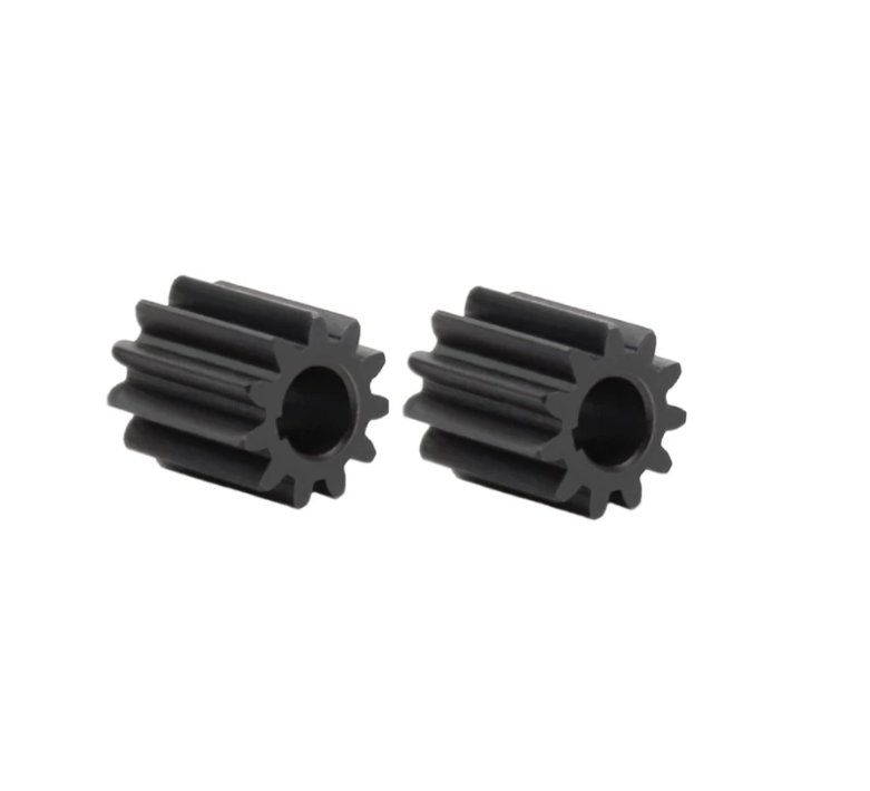
Tooth Number Constraints
I could not choose the pinion gear tooth numbers arbitrarily. I applied four geometric and assembly constraints. First, the ring gear must have a measurable tooth form. The addendum circle radius must not be smaller than the base circle radius:
$$d_a \ge d_b$$
With gear geometry, this becomes:
$$1 + \frac{2h_a^*}{Z_r} \ge \cos\alpha$$
Second, the center distances of the external and internal meshes must match. This requires:
$$Z_r = Z_s + 2Z_p$$
Third, for the pinion gears to be equally spaced and correctly assembled, the following condition must hold:
$$\frac{Z_r – Z_s}{C_s} = k, \quad k \in \mathbb{Z}$$
where \(C_s\) is the number of pinion gears. Fourth, adjacent pinion gears must not collide at their addendum circles. The clearance condition is:
$$h = R_p \sin\theta_p – 4d_a \ge h_{\min}$$
where \(R_p\) is the pinion gear center orbit radius, \(\theta_p\) is the angular spacing between adjacent pinion gears, and \(h_{\min}\) is the minimum allowable clearance. For an equally spaced set, I used:
$$R_p = a_s, \quad \theta_p = \frac{2\pi}{C_s}, \quad d_a = 4m(Z_p + 2h_a^*)$$
Substituting these into the clearance condition gives:
$$m(Z_s + Z_p)\sin\left(\frac{\pi}{C_s}\right) \ge m(Z_p + 2h_a^*) + h_{\min}$$
I solved these constraints with a compact seed meter envelope in mind. The ring gear pitch diameter was fixed at 205 mm. I used four pinion gears to distribute the disturbance and balance the load. The final tooth numbers and gear parameters are listed below.
| Parameter | Sun gear | Pinion gears | Ring gear |
|---|---|---|---|
| Tooth number \(Z\) | 18 | 32 | 82 |
| Module \(m\) (mm) | 2.5 | 2.5 | 2.5 |
| Pressure angle \(\alpha\) (°) | 20 | 20 | 20 |
| Helix angle \(\beta\) (°) | 0 | 0 | 0 |
| Face width \(b\) (mm) | 15 | 15 | 15 |
| Addendum coefficient \(h_a^*\) | 1 | 1 | 1.109 |
| Dedendum coefficient \(h_f^*\) | 1.25 | 1.25 | 1.104 |
| Bottom clearance coefficient \(c_n^*\) | 0.25 | 0.25 | −0.005 |
| Profile shift coefficient \(x\) | 0.415 | 0.295 | 1.157 |
| Pitch diameter \(d\) (mm) | 45 | 80 | 205 |
| Base diameter \(d_b\) (mm) | 42.29 | 75.18 | 192.63 |
| Working pitch diameter \(d’\) (mm) | 46.29 | 82.29 | 210.87 |
| Addendum diameter \(d_a\) (mm) | 52.08 | 86.48 | 205.24 |
| Root diameter \(d_f\) (mm) | 40.83 | 75.23 | 216.30 |
| Span tooth number \(k_0\) | 3 | 5 | 11 |
| Common normal length \(w_k\) (mm) | 19.79 | 34.84 | 82.34 |
| Measuring pin diameter \(d_m\) (mm) | 5.8 | 5.5 | 5.3 |
I used 40CrMo for the pinion gears and the other gear elements, with a module range between 1 mm and 3 mm. The accuracy grade was set to 9 according to ISO 1328. These choices reflect the low-speed, light-load nature of a mechanical seed meter. The pinion gears do not transmit high torque, but they must maintain accurate angular relationships because they drive the agitation ring. Any backlash or misalignment in the pinion gears would create an uneven disturbance field and would reduce filling consistency.
Agitation Ring and Disturbance-Assisted Filling
Structure and Geometric Design
The agitation ring is the final execution component of the planetary pinion gear drive. It converts the compound motion of the pinion gears into a periodic disturbance of the seed population. The ring body is circular, with an outer diameter of 25 mm and a thickness of 10 mm. It carries helical agitation rods made of thermoplastic polyurethane with a Shore hardness of 70D, an elongation at break greater than 300%, and a tensile strength of 35 MPa. I selected a polymer because it reduces seed damage and avoids severe blockage. The helical shape provides a gradual entry angle, so the rods disturb the seeds without producing a hard impact.
| Agitation ring parameter | Value |
|---|---|
| Ring diameter \(d_r\) (mm) | 25 |
| Ring thickness \(b_r\) (mm) | 10 |
| Rod diameter \(d_t\) (mm) | 6 |
| Helix turns | 1 |
| Rod length \(L_r\) (mm) | 20–32.5 |
| Rod number \(N_r\) | 1–6 |
| Material | TPU 70D |
The relative tangential speed between the agitation rod tip and the seed plate is:
$$v_t = \frac{2\pi}{60}|n_c – n_p|L_r$$
This speed determines the shear intensity in the disturbance zone. A higher relative speed increases local kinetic energy and improves seed fluidization. If the relative speed is too high, however, seeds rebound away from the cell entrance and the leakage rate increases. The volume swept by the agitation rods per unit time is:
$$V_e = N_r \pi d_t L_r v_t$$
This equation shows that both rod length and rod diameter increase the swept volume. In practice, rod length is the dominant factor because it controls the radial reach of the disturbance. Rod diameter mainly affects local contact force and shear rate. I therefore treated rod length and rod number as the main experimental factors, while keeping rod diameter at 6 mm.
The agitation length must satisfy coverage, non-interference, and geometric constraints. I derived three inequalities:
$$L_r < \frac{d_z – (d_s + d_p + d_r)}{2}$$
$$L_r < \frac{\sqrt{2}(d_s + d_p)}{4}$$
$$L_r > d_x$$
Here \(d_z\) is the seed plate diameter, \(d_s\) is the sun gear pitch diameter, \(d_p\) is the pinion gear pitch diameter, and \(d_x\) is the diameter at the connection between the cell and the seed plate. Substituting the design values gave an allowable agitation length range of approximately 20 mm to 32.5 mm. This range ensures assembly clearance while producing a useful disturbance field.
Disturbance Frequency and Seed Forces
The disturbance frequency is:
$$f_d = \frac{N_r |n_p – n_c|}{60}$$
Using the speed relation for the pinion gears, I obtained:
$$f_d = \frac{N_r n_c (Z_r – Z_p)}{60 Z_p}$$
This equation shows that the disturbance frequency increases with the number of agitation rods and with the seed plate speed. It also depends on the difference between the ring gear and pinion gear tooth numbers. In my design, the pinion gears are the source of this frequency because their rotation relative to the carrier sets the agitation ring speed.
The periodic disturbance creates a fluctuating contact force among seeds:
$$F_i = F_0 + \Delta F \sin(\omega_p t)$$
where \(F_0\) is the average static contact force, \(\Delta F\) is the disturbance amplitude, and \(\omega_p\) is the disturbance angular frequency. This periodic load breaks the static friction network above the cells and keeps the seed population in a fluidized state. As a result, seeds roll and slide more easily into the cells.
I also analyzed the force on a single seed in the filling zone. The agitation rod applies a resultant force \(F_r\), which can be decomposed into a normal component \(F_t\) and a tangential component \(F_n\). The normal component compresses the seed group and breaks arches. The tangential component drives rolling and sliding toward the cell. The seed also experiences support force \(F_s\), friction \(f\), centrifugal force \(F_c\), and gravity \(G\). The equilibrium equations are:
$$F_n + G\sin\gamma_g = F_s\cos\gamma_s + F_c\cos\gamma_c + f$$
$$F_t + F_s\sin\gamma_s = G\cos\gamma_g + F_c\sin\gamma_c$$
After substituting the force components, I obtained:
$$F_r\sin\theta = F_s(\cos\gamma_s + \mu)\cos\gamma_s + m_0\omega_s^2 r\cos\gamma_c – m_0 g\sin\gamma_g$$
$$F_r\cos\theta = m_0 g\cos\gamma_g + m_0\omega_s^2 r\sin\gamma_c – F_s\sin\gamma_s$$
The resultant force and its direction angle are:
$$F_r = \sqrt{\left[F_s(\cos\gamma_s + \mu) + m_0\omega_s^2 r\cos\gamma_c – m_0 g\sin\gamma_g\right]^2 + \left[m_0 g\cos\gamma_g + m_0\omega_s^2 r\sin\gamma_c – F_s\sin\gamma_s\right]^2}$$
$$\theta = \arctan\left(\frac{F_s(\cos\gamma_s + \mu) + m_0\omega_s^2 r\cos\gamma_c – m_0 g\sin\gamma_g}{m_0 g\cos\gamma_g + m_0\omega_s^2 r\sin\gamma_c – F_s\sin\gamma_s}\right)$$
The angle \(\theta\) determines the nature of the filling assistance. If \(\theta\) is in a suitable range, the normal component breaks static structures without excessive impact, while the tangential component promotes seed rolling and sliding. The pinion gear driven reverse motion makes this angle continuously variable in time, which prevents the formation of a stable dead zone.
| Force component | Physical role | Effect of increasing parameter |
|---|---|---|
| \(F_t\) | Normal compression | Breaks arches; too high causes rebound |
| \(F_n\) | Tangential drive | Promotes rolling and sliding into cell |
| \(F_s\) | Support from neighboring seeds | High support stabilizes arches and reduces filling |
| \(F_c\) | Centrifugal effect | Can press seeds against cell or disturb trajectory |
| \(G\) | Gravity | Assists cleaning and dropping |
Seed Plate and Cell Arrangement
The seed plate also serves as the planetary carrier. It is connected coaxially to the planetary pinion gear train. It receives the input motion and distributes seeds. Its diameter controls the number of cells and the filling arc. I derived the filling time as:
$$t = \frac{60\alpha_f r_c}{n_c \pi d_z}$$
where \(\alpha_f\) is the filling-zone angle, \(r_c\) is the cell center radius, and \(d_z\) is the seed plate diameter. This equation shows that increasing the plate diameter or reducing the speed increases the filling time. A larger plate also allows more cells, which reduces the required rotational speed for a given seeding rate. In my design, the seed plate diameter was 225 mm and its thickness was 3 mm. Four planetary shaft holes of 17 mm diameter were evenly distributed. Shallow guide grooves of 0.3 mm depth were placed between cells to guide seeds into the cells.
The number of cells is:
$$N_k = \frac{2\pi r_c}{w_c}$$
where \(w_c\) is the cell spacing. The cell spacing must be greater than about 1.5 times the maximum seed length to avoid interference during filling. The measured seed length implied a minimum spacing of 22.4 mm. I selected 24 mm. With a cell center radius of 105 mm, the calculated number was 27.49. I therefore used 27 cells. The relationship between seed plate speed and forward speed is:
$$n_c = \frac{2500 v_m}{3 N_k z}$$
where \(v_m\) is the forward speed in km/h and \(z\) is the target seed spacing in mm. For a target spacing of 25 mm and a forward speed range of 8–20 km/h, the seed plate speed is approximately 20–50 r/min.
| Seed plate parameter | Value |
|---|---|
| Outer diameter \(d_z\) (mm) | 225 |
| Thickness \(b_z\) (mm) | 3 |
| Planetary shaft hole diameter \(d_h\) (mm) | 17 |
| Number of planetary shafts | 4 |
| Cell center radius \(r_c\) (mm) | 105 |
| Cell spacing \(w_c\) (mm) | 24 |
| Number of cells \(N_k\) | 27 |
| Guide groove depth (mm) | 0.3 |
Experimental Setup and Single-Factor Tests
I conducted bench experiments to quantify the effects of agitation length, rod number, and forward speed. The test bench included a speed-controlled motor, a chain drive, a PVC conveyor belt, a high-speed camera, and a motion analysis system. The camera was positioned horizontally with the belt surface, and the field of view was adjusted so that the seed drop from the tube was fully captured. I used a frame rate of 480 f/s and a resolution of 720 pixels. For each run, I collected more than 250 consecutive seeds and analyzed the middle stable segment.
| Equipment | Specification |
|---|---|
| Drive motor | 0–50 r/min speed control |
| Conveyor belt | PVC, 0–16 km/h linear speed |
| Conveyor motor | 60 W permanent magnet motor |
| High-speed camera | 720 pixels, 480 f/s |
| Motion analysis | Tracker software for seed spacing |
| Seed sample | Ungraded dent maize |
| Target spacing | 25 cm |
I followed the national test method for single-seed precision drills. The evaluation indices were qualified rate \(A\), multiple rate \(D\), and leakage rate \(M\). Each treatment was repeated three times, and the mean was used. I first performed single-factor tests to determine reasonable ranges. In these tests, I varied one factor while holding the others at a reference level. The reference levels were 30 mm agitation length, 3 rods, and 12 km/h forward speed.
| Factor | Levels tested | Observed trend | Selected range |
|---|---|---|---|
| Agitation length \(L_r\) (mm) | 26, 28, 30, 32, 34 | Qualified rate peaks near 30 mm | 28–32 |
| Rod number \(N_r\) | 1, 2, 3, 4, 5, 6 | Qualified rate peaks near 4; excessive rods reduce stability | 2–4 |
| Forward speed \(v_m\) (km/h) | 8, 10, 12, 14, 16 | Qualified rate peaks at 12 km/h | 10–14 |
The single-factor results revealed important interactions. When the agitation length was too short, the disturbance did not reach the far side of the filling zone. Seeds remained in a relatively static state, and some cells passed without seed capture. When the agitation length was too long, the rod tips moved too fast and disturbed the trajectory of seeds that were about to enter the cells. This increased both multiple and leakage rates. The rod number showed a similar optimum. With one or two rods, the disturbance frequency was too low, and seeds could settle between successive sweeps. With five or six rods, the seed population became over-agitated, collisions between seeds increased, and the cell entrance was periodically blocked by moving seeds.
Forward speed had the strongest effect on the qualified rate. At 8 km/h, the filling time was long, so leakage was low, but the seed population sometimes moved too slowly and multiple seeds could enter the cell. At 12 km/h, the combination of centrifugal force, gravity, and pinion gear driven agitation produced a well-fluidized population, giving the highest qualified rate and the lowest multiple rate. Above 14 km/h, the filling time became too short, and the centrifugal effect became too strong. Seeds tended to rebound from the cell or remain pressed against the cell edge, so multiple and leakage rates both increased.
Response Surface Experiment and Modeling
I used a Box–Behnken design with three factors and three levels. The factors were agitation length \(X_1\), rod number \(X_2\), and forward speed \(X_3\). The coded levels are shown below.
| Coded level | Agitation length \(X_1\) (mm) | Rod number \(X_2\) | Forward speed \(X_3\) (km/h) |
|---|---|---|---|
| −1 | 28 | 2 | 10 |
| 0 | 30 | 3 | 12 |
| +1 | 32 | 4 | 14 |
I generated 17 experimental runs and measured the qualified rate \(Y_1\), multiple rate \(Y_2\), and leakage rate \(Y_3\). The design matrix and results are given in the following table.
| Run | \(X_1\) | \(X_2\) | \(X_3\) | \(Y_1\) (%) | \(Y_2\) (%) | \(Y_3\) (%) |
|---|---|---|---|---|---|---|
| 1 | 0 | 0 | 0 | 92.36 | 4.04 | 3.60 |
| 2 | 1 | 1 | 0 | 90.79 | 4.10 | 5.11 |
| 3 | 0 | −1 | 1 | 90.51 | 5.06 | 4.43 |
| 4 | −1 | 1 | 0 | 88.58 | 6.40 | 5.02 |
| 5 | −1 | 0 | 1 | 89.08 | 6.63 | 4.29 |
| 6 | 0 | 0 | 0 | 92.44 | 4.09 | 3.47 |
| 7 | 0 | 0 | 0 | 93.02 | 3.46 | 3.52 |
| 8 | −1 | −1 | 0 | 89.99 | 5.28 | 4.73 |
| 9 | 0 | 0 | 0 | 92.11 | 4.54 | 3.35 |
| 10 | 1 | −1 | 0 | 89.12 | 6.14 | 4.74 |
| 11 | 0 | −1 | −1 | 88.97 | 5.61 | 5.42 |
| 12 | 1 | 0 | −1 | 88.22 | 6.45 | 5.33 |
| 13 | 0 | 0 | 0 | 92.73 | 3.78 | 3.49 |
| 14 | 0 | 1 | −1 | 88.84 | 5.54 | 5.62 |
| 15 | 0 | 1 | 1 | 90.15 | 5.08 | 4.77 |
| 16 | 1 | 0 | 1 | 89.74 | 5.13 | 5.13 |
| 17 | −1 | 0 | −1 | 87.94 | 6.05 | 6.01 |
Qualified Rate Model
The quadratic regression model for the qualified rate is:
$$Y_1 = 92.53 + 0.285X_1 – 0.0287X_2 + 0.6888X_3 + 0.77X_1X_2 + 0.095X_1X_3 – 0.0575X_2X_3 – 1.89X_1^2 – 1.02X_2^2 – 1.89X_3^2$$
The analysis of variance for this model is shown below. The model was highly significant, and the lack-of-fit was not significant. The coefficient of determination was 0.9871, and the adjusted coefficient of determination was 0.9706. These values indicate that the model can predict the qualified rate well within the experimental range.
| Source | Sum of squares | df | Mean square | F value | p-value |
|---|---|---|---|---|---|
| Model | 45.15 | 9 | 5.02 | 59.69 | <0.0001 |
| \(X_1\) | 0.6498 | 1 | 0.6498 | 7.73 | 0.0273 |
| \(X_2\) | 0.0066 | 1 | 0.0066 | 0.0787 | 0.7872 |
| \(X_3\) | 3.8 | 1 | 3.8 | 45.16 | 0.0003 |
| \(X_1X_2\) | 2.37 | 1 | 2.37 | 28.22 | 0.0011 |
| \(X_1X_3\) | 0.0361 | 1 | 0.0361 | 0.4295 | 0.5332 |
| \(X_2X_3\) | 0.0132 | 1 | 0.0132 | 0.1574 | 0.7034 |
| \(X_1^2\) | 15.08 | 1 | 15.08 | 179.39 | <0.0001 |
| \(X_2^2\) | 4.38 | 1 | 4.38 | 52.1 | 0.0002 |
| \(X_3^2\) | 15.12 | 1 | 15.12 | 179.86 | <0.0001 |
| Residual | 0.5883 | 7 | 0.084 | ||
| Lack of fit | 0.0948 | 3 | 0.0316 | 0.2562 | 0.8539 |
| Pure error | 0.4935 | 4 | 0.1234 | ||
| Total | 45.74 | 16 |
The significant terms were \(X_3\), \(X_1^2\), \(X_2^2\), \(X_3^2\), and \(X_1X_2\). The agitation length \(X_1\) was also significant. The order of factor influence on the qualified rate was forward speed, agitation length, and rod number. The interaction between agitation length and rod number was important because the disturbance field depends on both the reach and the frequency of the agitation rods. The pinion gears determine the frequency through their reverse rotation, but the geometric reach is set by the agitation length. When these two parameters are well matched, the qualified rate reaches a maximum.
Multiple Rate Model
The quadratic regression model for the multiple rate is:
$$Y_2 = 3.49 + 0.0325X_1 + 0.15X_2 – 0.47X_3 + 0.02X_1X_2 + 0.38X_1X_3 + 0.035X_2X_3 + 0.772X_1^2 + 0.642X_2^2 + 0.932X_3^2$$
The analysis of variance for the multiple rate is given below. The model was highly significant, and the lack-of-fit was not significant. The coefficient of determination was 0.9532, and the adjusted coefficient of determination was 0.893. The order of factor influence on the multiple rate was agitation length, forward speed, and rod number.
| Source | Sum of squares | df | Mean square | F value | p-value |
|---|---|---|---|---|---|
| Model | 15.43 | 9 | 1.71 | 15.84 | 0.0007 |
| \(X_1\) | 0.8064 | 1 | 0.8064 | 7.45 | 0.0294 |
| \(X_2\) | 0.1176 | 1 | 0.1176 | 1.09 | 0.3319 |
| \(X_3\) | 0.3828 | 1 | 0.3828 | 3.54 | 0.1021 |
| \(X_1X_2\) | 2.5 | 1 | 2.5 | 23.06 | 0.002 |
| \(X_1X_3\) | 0.9025 | 1 | 0.9025 | 8.34 | 0.0234 |
| \(X_2X_3\) | 0.002 | 1 | 0.002 | 0.0187 | 0.8951 |
| \(X_1^2\) | 5.28 | 1 | 5.28 | 48.81 | 0.0002 |
| \(X_2^2\) | 0.6008 | 1 | 0.6008 | 5.55 | 0.0507 |
| \(X_3^2\) | 3.9 | 1 | 3.9 | 36.05 | 0.0005 |
| Residual | 0.7579 | 7 | 0.1083 | ||
| Lack of fit | 0.1182 | 3 | 0.0394 | 0.2463 | 0.0582 |
| Pure error | 0.6397 | 4 | 0.1599 | ||
| Total | 16.19 | 16 |
The multiple rate decreased as the agitation length increased from a low level, because the disturbance broke seed clusters before they could enter the cell. However, when the agitation length became too large, the impact energy increased, and seeds that had already been rejected could be pushed back into the cell. The rod number also affected the multiple rate. A higher rod number increased the disturbance frequency and reduced the time during which seeds could settle into a stable cluster. However, an excessively high rod number caused over-agitation and reduced the stability of the filling process. The interaction between agitation length and forward speed was significant because both affect the time available for multiple seeds to enter the cell. At high speed, the cleaning time is shorter, so the agitation must be strong enough to prevent multiple capture but not so strong as to disturb the single seed.
Leakage Rate Model
The quadratic regression model for the leakage rate is:
$$Y_3 = 3.98 – 0.3175X_1 – 0.1212X_2 – 0.2188X_3 – 0.79X_1X_2 – 0.475X_1X_3 + 0.0225X_2X_3 + 1.12X_1^2 + 0.3777X_2^2 + 0.9628X_3^2$$
The analysis of variance for the leakage rate is shown below. The model was highly significant, and the lack-of-fit was not significant. The coefficient of determination was 0.9968, and the adjusted coefficient of determination was 0.8928. The order of factor influence on the leakage rate was forward speed, rod number, and agitation length.
| Source | Sum of squares | df | Mean square | F value | p-value |
|---|---|---|---|---|---|
| Model | 11.34 | 9 | 1.26 | 245.24 | <0.0001 |
| \(X_1\) | 0.0084 | 1 | 0.0084 | 1.64 | 0.2405 |
| \(X_2\) | 0.18 | 1 | 0.18 | 35.03 | 0.0006 |
| \(X_3\) | 1.77 | 1 | 1.77 | 343.91 | <0.0001 |
| \(X_1X_2\) | 0.0016 | 1 | 0.0016 | 0.3114 | 0.5942 |
| \(X_1X_3\) | 0.5776 | 1 | 0.5776 | 112.4 | <0.0001 |
| \(X_2X_3\) | 0.0049 | 1 | 0.0049 | 0.9536 | 0.3613 |
| \(X_1^2\) | 2.51 | 1 | 2.51 | 488.35 | <0.0001 |
| \(X_2^2\) | 1.74 | 1 | 1.74 | 337.73 | <0.0001 |
| \(X_3^2\) | 3.66 | 1 | 3.66 | 711.75 | <0.0001 |
| Residual | 0.036 | 7 | 0.0051 | ||
| Lack of fit | 0.0033 | 3 | 0.001 | 0.1235 | 0.9414 |
| Pure error | 0.0329 | 4 | 0.0082 | ||
| Total | 11.38 | 16 |
The leakage rate increased sharply when the forward speed exceeded the optimal range. At high speed, the filling time is short, and the seed population cannot respond quickly enough to the disturbance. The pinion gear driven agitation still creates a disturbance, but the seeds do not have enough time to move into the cell. The leakage rate also increased when the rod number was too low or too high. With too few rods, the disturbance frequency was insufficient, and arches formed in the filling zone. With too many rods, the seeds were over-agitated, and some seeds were driven away from the cell entrance. The interaction between agitation length and forward speed was highly significant because the effective disturbance intensity depends on both the rod tip speed and the available filling time.
Multi-Objective Optimization
I formulated the optimization problem to maximize the qualified rate while minimizing the multiple and leakage rates:
$$\max Y_1, \quad \min Y_2, \quad \min Y_3$$
subject to:
$$-1 \le X_1 \le 1$$
$$-1 \le X_2 \le 1$$
$$-1 \le X_3 \le 1$$
The numerical optimization gave an agitation length of 30.16 mm, a rod number of 3.008, and a forward speed of 12.37 km/h. The predicted qualified rate was 92.61%, the multiple rate was 3.95%, and the leakage rate was 3.46%. For practical manufacturing and adjustment, I rounded these values to an agitation length of 30 mm, a rod number of 3, and a forward speed of 12 km/h. This combination is my recommended parameter set.
| Parameter | Numerical optimum | Practical adjustment |
|---|---|---|
| Agitation length (mm) | 30.16 | 30 |
| Rod number | 3.008 | 3 |
| Forward speed (km/h) | 12.37 | 12 |
| Predicted qualified rate (%) | 92.61 | — |
| Predicted multiple rate (%) | 3.95 | — |
| Predicted leakage rate (%) | 3.46 | — |
Field Validation
I validated the optimized parameters in a field trial. The soil was a brown loam, and I selected a flat, loose area to reduce vibration effects. The forward speed was set to 12 km/h, the agitation length to 30 mm, and the rod number to 3. I performed three parallel runs. The measured qualified rate was 91.42%, the multiple rate was 4.35%, and the leakage rate was 4.23%. These values are close to the bench predictions. The small differences are caused by non-structured field conditions such as vibration, ground unevenness, and speed fluctuation. Nevertheless, the field results confirm that the planetary pinion gear driven disturbance-assisted meter can satisfy the requirements of high-speed mechanical maize precision seeding.
| Run | Qualified rate (%) | Multiple rate (%) | Leakage rate (%) |
|---|---|---|---|
| 1 | 92.17 | 4.42 | 3.82 |
| 2 | 91.13 | 4.14 | 4.31 |
| 3 | 90.96 | 4.49 | 4.56 |
| Mean | 91.42 | 4.35 | 4.23 |
I also compared the performance of my planetary pinion gear driven meter with two conventional mechanical meters at 12 km/h. The comparison is shown below. The planetary pinion gear driven disturbance-assisted meter achieved a higher qualified rate and a much lower leakage rate. The multiple rate was also well controlled. This comparison supports my conclusion that the reverse differential disturbance produced by the pinion gears is effective for high-speed filling.
| Meter type | Qualified rate (%) | Multiple rate (%) | Leakage rate (%) |
|---|---|---|---|
| Planetary pinion gear driven disturbance-assisted | 91.42 | 4.35 | 4.23 |
| Spoon-wheel type | 84.50 | 6.80 | 8.70 |
| Finger-clamp type | 82.80 | 4.38 | 12.82 |
Discussion
The results of my study show that the pinion gears in an NGW planetary train can do more than transmit motion. They can generate a reverse, non-isochronous agitation motion that improves the filling process. In a conventional mechanical meter, the seed plate and the agitation element often rotate together or with limited relative motion. The disturbance is therefore weak, especially at high speed. In my design, the pinion gears rotate opposite to the seed plate, and the agitation ring mounted on the pinion gear shafts sweeps over the cells with a different speed. This creates a time-varying shear field above the cells. The field breaks arches, reduces static friction, and keeps seeds in a fluidized state. As a result, the filling window is used more efficiently even when the forward speed is high.
The experiments also show that the disturbance must be tuned. If the agitation length is too short, the disturbance does not reach the entire filling zone. If it is too long, the rod tip speed is too high, and seeds are driven away from the cells. If the rod number is too small, the disturbance frequency is too low, and seeds can settle between sweeps. If the rod number is too large, the seed population is over-agitated, and collisions reduce filling stability. The pinion gear train provides a compact way to achieve the required reverse motion, but the final performance depends on the matching among agitation length, rod number, and forward speed.
I found that the forward speed has the strongest influence on the qualified rate and leakage rate. This is expected because speed directly reduces the filling time. The pinion gear driven agitation compensates for this reduction by increasing the effective mobility of the seed population. However, the compensation has limits. Above 14 km/h, the leakage rate rises rapidly even with optimized agitation. This suggests that further improvements at very high speed may require additional measures, such as a larger seed plate, more cells, or a different cell geometry. The planetary pinion gear concept can be combined with these measures because the pinion gears and agitation ring are modular.
The multiple rate is influenced mainly by agitation length and its interaction with rod number. A moderate agitation length breaks clusters without pushing rejected seeds back into the cell. A moderate rod number maintains a high disturbance frequency without over-agitating the population. The interaction between agitation length and forward speed is also important because the cleaning stage depends on the available time and on the centrifugal force. At high speed, the centrifugal force presses seeds against the cell edge and increases the force required for cleaning. The agitation must be strong enough to prevent multiple capture but not so strong as to disturb the single seed that should remain in the cell.
The field validation confirms the bench results. The mean qualified rate was 91.42%, the multiple rate was 4.35%, and the leakage rate was 4.23%. These values meet the requirements for mechanical maize precision seeding at high speed. The comparison with spoon-wheel and finger-clamp meters shows a clear advantage in qualified rate and leakage rate. The planetary pinion gear driven disturbance-assisted meter therefore offers a practical alternative to pneumatic meters for high-speed maize seeding, especially where simplicity, low cost, and low energy demand are important.
Conclusions
I designed and tested a planetary pinion gear driven disturbance-assisted precision maize seed-metering device. The main conclusions are as follows.
First, the NGW planetary train with pinion gears provides a compact and effective way to create reverse differential motion between the seed plate and the agitation ring. The kinematic relationships are:
$$i = \frac{n_s}{n_c} = 1 + \frac{Z_r}{Z_s}$$
$$n_p = -\frac{Z_r}{Z_p} n_c$$
These equations show that the pinion gears rotate opposite to the carrier. The agitation ring therefore rotates opposite to the seed plate. This reverse motion is the source of the disturbance-assisted filling effect.
Second, the agitation length, rod number, and forward speed are the main factors affecting the qualified, multiple, and leakage rates. The single-factor tests gave reasonable ranges of 28–32 mm for agitation length, 2–4 for rod number, and 10–14 km/h for forward speed. The response surface models showed that the order of influence on the qualified rate was forward speed, agitation length, and rod number. The order of influence on the multiple rate was agitation length, forward speed, and rod number. The order of influence on the leakage rate was forward speed, rod number, and agitation length.
Third, the optimized parameter combination was an agitation length of 30 mm, a rod number of 3, and a forward speed of 12 km/h. Under these conditions, the predicted qualified rate was 92.61%, the multiple rate was 3.95%, and the leakage rate was 3.46%. The field validation gave a qualified rate of 91.42%, a multiple rate of 4.35%, and a leakage rate of 4.23%. These values satisfy the requirements for high-speed mechanical maize precision seeding.
Fourth, the planetary pinion gear driven disturbance-assisted meter outperformed conventional spoon-wheel and finger-clamp meters at 12 km/h. The qualified rate increased by about 7–9 percentage points, and the leakage rate decreased by about 4–8 percentage points. The multiple rate remained low. This confirms that the pinion gear driven reverse agitation is an effective solution to the high-speed filling problem in mechanical maize meters.
In future work, I plan to study the wear and fatigue behavior of the pinion gears and the agitation rods under long-term field operation. I also plan to investigate how the pinion gear tooth number and the agitation ring geometry can be co-optimized for different maize seed sizes and shapes. The results of this study provide a theoretical and technical basis for the structural design and parameter optimization of high-speed mechanical maize precision seed-metering devices.