
I investigate the feasibility of a gear-driven opening and closing system for a large sector gate used in coastal tidal defense. The sector gate consists of a central leaf and two side discs. When the gate is not in operation, the leaf rests horizontally inside a recess in the riverbed, and the side discs remain largely hidden inside the piers. This arrangement gives the sector gate strong landscape compatibility, low visual obstruction, and good navigational clearance. However, the drive system is the critical challenge. Conventional hydraulic cylinders with linkages require an above-pier machinery house and an operating platform, which weakens the hidden nature of the gate. I therefore propose an internal gear drive in which several pinion gears engage a large ring gear mounted on each side disc. The pinion gears are driven by motors and multistage reducers installed inside the piers. In this way, the main drive components can be concealed, and the visual impact on the waterway is reduced.
The central question in my study is whether such a gear drive can survive the large opening torque and the span-induced deflection of a sector gate. Because the gate spans a wide waterway, water pressure and self-weight produce bending and torsional deformation. This deformation causes the large ring gear to rotate slightly relative to the pinion gears. The resulting angular misalignment changes the contact pattern, concentrates load on one edge of the teeth, and may cause scuffing, pitting, and abnormal wear. I use finite element analysis in ANSYS Workbench to model the gear pair, evaluate the root bending stress and tooth contact stress, and determine whether a lead modification of the pinion gears can make the system feasible.
I begin with the torque distribution. The maximum opening torque on one side of the gate is taken as 63877 kN m. Each side has three pinion gears, and the total reduction ratio from each pinion gear to the large ring gear is 13. I assume that the three pinion gears share the load equally in the design calculation. The torque transmitted by each pinion gear is therefore obtained from the total torque divided by the number of pinion gears and the reduction ratio.
$$T_1 = \frac{T_{\max}}{n i} = \frac{63877}{3 \times 13} \approx 1637 \ \text{kN m}$$
Here, Tmax is the maximum opening torque on one side, n is the number of pinion gears per side, i is the reduction ratio, and T1 is the torque on each pinion gear. This torque is the basis for the subsequent bending strength calculation, contact stress calculation, and finite element load application.
| Parameter | Symbol | Value | Unit |
| Maximum opening torque per side | Tmax | 63877 | kN m |
| Number of pinion gears per side | n | 3 | — |
| Total reduction ratio | i | 13 | — |
| Torque per pinion gear | T1 | 1637 | kN m |
| Pressure angle | α | 20 | ° |
| Module | mt | 50 | mm |
| Pinion gear tooth number | Z1 | 23 | — |
| Large ring gear tooth number | Z2 | 300 | — |
I select an external spur gear arrangement for the drive. The pinion gears and the large ring gear are made of 20CrMnTi, carburized and quenched, with a gear accuracy grade of 7. The preliminary pinion gear tooth number is 23, and the large ring gear tooth number is 300. The actual reduction ratio is therefore the ratio of the large ring gear tooth number to the pinion gear tooth number.
$$i_{\text{actual}} = \frac{Z_2}{Z_1} = \frac{300}{23} = 13.04$$
The pitch diameters follow directly from the module and tooth numbers. For the pinion gears, I obtain a pitch diameter of 1150 mm. For the large ring gear, I obtain a pitch diameter of 15000 mm. The center distance is half the sum of the two pitch diameters.
$$d_1 = m_t Z_1 = 50 \times 23 = 1150 \ \text{mm}$$
$$d_2 = m_t Z_2 = 50 \times 300 = 15000 \ \text{mm}$$
$$a = \frac{d_1 + d_2}{2} = \frac{1150 + 15000}{2} = 8075 \ \text{mm}$$
I choose a face width coefficient of 0.5. The face width of the large ring gear becomes 575 mm, and the face width of the pinion gears is increased slightly to 580 mm to allow for installation error and edge contact. The main gear parameters are summarized in the following table.
| Item | Pinion gears | Large ring gear |
| Material | 20CrMnTi | 20CrMnTi |
| Heat treatment | Carburized and quenched | Carburized and quenched |
| Accuracy grade | 7 | 7 |
| Module | 50 mm | 50 mm |
| Tooth number | 23 | 300 |
| Pitch diameter | 1150 mm | 15000 mm |
| Face width | 580 mm | 575 mm |
| Center distance | 8075 mm | |
| Pressure angle | 20° | |
| Reduction ratio | 13.04 | |
Because the drive is an open gear system and the speed is very low, I use the tooth root bending fatigue strength as the primary design criterion. The bending strength design formula for the normal module is written as follows.
$$m_t \ge \sqrt[3]{\frac{2 K_{Ft} T_1 Y_\varepsilon}{\phi_d Z_1^2} \cdot \frac{Y_{Fa}Y_{Sa}}{[\sigma_F]}}$$
In this expression, KFt is the load factor used in the preliminary calculation, Yε is the contact ratio factor, φd is the face width coefficient, YFa is the tooth form factor, YSa is the stress correction factor, and [σF] is the allowable bending stress. I first estimate the contact ratio of the gear pair. Using the preliminary tooth numbers, I obtain a contact ratio of 1.71.
$$\varepsilon_\alpha = 1.88 – 3.2\left(\frac{1}{Z_1}+\frac{1}{Z_2}\right) = 1.71$$
The contact ratio factor is then calculated from the contact ratio.
$$Y_\varepsilon = 0.25 + \frac{0.75}{\varepsilon_\alpha} = 0.25 + \frac{0.75}{1.71} = 0.688$$
I take the preliminary load factor KFt as 1.5. The actual load factor is obtained from the product of the service factor, dynamic factor, transverse load distribution factor, and face load distribution factor.
$$K_F = K_A K_V K_{F\alpha} K_{F\beta}$$
For this low-speed, high-torque application, I select KA as 1.0, KV as 1.0, KFα as 1.3, and KFβ as 1.2. The resulting load factor is close to the preliminary value, so I do not need to repeat the module calculation.
$$K_F = 1.0 \times 1.0 \times 1.3 \times 1.2 = 1.56$$
The allowable bending stress is determined from the bending fatigue limit, the bending fatigue life factor, and the bending safety factor.
$$[\sigma_F] = \frac{\sigma_{F\lim} K_{FN}}{S_F}$$
For both gears, the bending fatigue limit is 500 MPa. I calculate the stress cycles from the operating schedule. The gate closes for astronomical tides and typhoons. I assume two astronomical tide events per month and ten typhoon events per year. The gate therefore operates about 34 days per year, and each operating day is taken as one hour of gear rotation. With a pinion gear speed of 0.1 r/min, the stress cycle number for the pinion gears is as follows.
$$N_1 = 60 n j L_h = 60 \times 0.1 \times 1 \times 1 \times 34 \times 200 = 4.1 \times 10^4$$
The stress cycle number for the large ring gear is reduced by the reduction ratio.
$$N_2 = \frac{N_1}{i} = \frac{4.1 \times 10^4}{13} = 3.15 \times 10^3$$
From the relevant design data, I take the bending fatigue life factor of the pinion gears as 1.75 and that of the large ring gear as 2.25. Because the gate must have high reliability, I choose a bending safety factor of 2. The allowable bending stresses become the following values.
$$[\sigma_{F1}] = \frac{\sigma_{F\lim 1} K_{FN1}}{S_F} = \frac{500 \times 1.75}{2} = 437.5 \ \text{MPa}$$
$$[\sigma_{F2}] = \frac{\sigma_{F\lim 2} K_{FN2}}{S_F} = \frac{500 \times 2.25}{2} = 562.5 \ \text{MPa}$$
I compare the tooth form factor and stress correction factor ratios for the pinion gears and the large ring gear. For the pinion gears, YFa1 is 2.82 and YSa1 is 1.55. For the large ring gear, YFa2 is 2.10 and YSa2 is 1.85.
$$\frac{Y_{Fa1}Y_{Sa1}}{[\sigma_{F1}]} = \frac{2.82 \times 1.55}{437.5} = 0.010$$
$$\frac{Y_{Fa2}Y_{Sa2}}{[\sigma_{F2}]} = \frac{2.10 \times 1.85}{562.5} = 0.007$$
The larger value controls the design. Using 0.010 in the module formula gives a required module of 50.36 mm. I round this value to the standard module of 50 mm. This choice satisfies the bending strength requirement.
$$m_t \ge 50.36 \ \text{mm} \quad \Rightarrow \quad m_t = 50 \ \text{mm}$$
I also check the allowable contact stress. The contact fatigue limit of the carburized and quenched 20CrMnTi gear pair is taken as 1500 MPa. The contact fatigue life factor is 1.6, and the contact safety factor is 1.6. The allowable contact stress is therefore 1500 MPa.
$$[\sigma_H] = \frac{\sigma_{H\lim} K_{HN}}{S_H} = \frac{1500 \times 1.6}{1.6} = 1500 \ \text{MPa}$$
The allowable bending stresses are 437.5 MPa for the pinion gears and 562.5 MPa for the large ring gear. These values are used as the acceptance criteria in the finite element analysis. The main allowable stresses are listed below.
| Stress type | Pinion gears | Large ring gear | Unit |
| Allowable root bending stress | 437.5 | 562.5 | MPa |
| Allowable contact stress | 1500 | 1500 | MPa |
For the finite element analysis, I build a solid model of the pinion gears and the large ring gear and import it into ANSYS Workbench. Because the rotational speed is very low, I use a static structural analysis rather than a transient dynamic analysis. The pitch line velocity of the pinion gears is only about 0.006 m/s, which further supports the static assumption.
$$v = \frac{\pi d_1 n_1}{60} = \frac{\pi \times 1.15 \times 0.1}{60} = 0.00602 \ \text{m/s}$$
The finite element model includes five pairs of contacting teeth. I apply the maximum opening torque of 1637 kN m to each pinion gear. The inner cylindrical surface of the large ring gear is fixed. The pinion gears are allowed to rotate about their own axes, while all other degrees of freedom are constrained. The contact between the teeth is modeled as frictional contact with a friction coefficient of 0.1. The material properties are assigned as follows.
| Property | Value | Unit |
| Material | 20CrMnTi | — |
| Elastic modulus | 212 | GPa |
| Poisson ratio | 0.289 | — |
| Density | 7869 | kg/m³ |
| Heat treatment | Carburized and quenched | — |
| Gear accuracy grade | 7 | — |
The boundary conditions and load cases are summarized in the next table. I consider two misalignment cases. The first case assumes perfect alignment, with a ring gear misalignment angle of zero. The second case assumes a misalignment angle of 0.25°, which is slightly above the design limit of 0.246°. This conservative assumption allows me to examine the worst expected contact condition caused by gate deflection.
| Item | Condition |
| Analysis type | Static structural |
| Contact pairs | Five tooth pairs |
| Friction coefficient | 0.1 |
| Large ring gear constraint | Inner surface fixed |
| Pinion gear constraint | Axial rotation free, other degrees of freedom constrained |
| Applied torque per pinion gear | 1637 kN m |
| Misalignment case 1 | 0° |
| Misalignment case 2 | 0.25° |
I determine the critical stress locations before running the full contact analysis. For root bending stress, the critical condition occurs when a single pair of teeth carries the load near the tooth tip. For contact stress, I evaluate the pitch point region because pitting often begins near the pitch line on the flank. This approach simplifies the calculation while preserving the main failure modes of the pinion gears and the large ring gear.
The finite element results before modification are shown in the following table. At zero misalignment, all stresses are well below the allowable values. The maximum root bending stress of the large ring gear is 240.8 MPa, and that of the pinion gears is 306.6 MPa. The maximum contact stress on the large ring gear is 310.4 MPa, and that on the pinion gears is 352.93 MPa. These values indicate that the gear drive is safe when the ring gear and pinion gears are perfectly aligned.
| Misalignment angle α | Large ring gear root stress | Pinion gear root stress | Large ring gear contact stress | Pinion gear contact stress |
| 0° | 240.8 MPa | 306.6 MPa | 310.4 MPa | 352.93 MPa |
| 0.25° | 261.9 MPa | 311.8 MPa | 1128.5 MPa | 384.70 MPa |
When the misalignment angle increases to 0.25°, the root bending stresses increase only moderately. However, the contact stress on the large ring gear rises sharply to 1128.5 MPa. Although this value is still below the allowable contact stress of 1500 MPa, the contact area shifts toward one edge of the tooth. This edge effect creates a local stress concentration that is not fully represented by the maximum stress alone. Under repeated operation, the edge-loaded condition can lead to cold scuffing, pitting, and abnormal wear. The pinion gears also experience an increase in contact stress, reaching 384.70 MPa, but the large ring gear is more severely affected because of its larger diameter and greater sensitivity to angular misalignment.
The edge effect is the main reason why the unmodified gear drive cannot be accepted without further treatment. The large ring gear is not rigid in the absolute sense. The gate leaf and side discs deflect under water pressure, and the deflection changes the relative angle between the pinion gears and the large ring gear. Even a small angular deviation can move the contact band to the tooth edge. When this happens, the effective contact width decreases, the local contact stress increases, and the lubricant film becomes more likely to break down. I therefore introduce a lead modification, specifically a crowning modification, on the pinion gears.
For the pinion gears, I use a crowning modification along the face width. The objective is to remove the sharp edge contact and distribute the load more evenly across the central part of the tooth. The crowning amount is calculated from the effective contact width, the mesh misalignment, and the full face width.
$$C_c = \frac{b_{cal} F_{\beta y}}{b}$$
In this equation, bcal is the effective contact width, Fβy is the mesh misalignment, b is the face width, and Cc is the crowning amount. For the 0.25° misalignment case, I find that the effective contact width is 0.862 times the full face width. The mesh misalignment is 0.35 mm. The crowning amount is therefore calculated as follows.
$$b_{cal} = 0.862b$$
$$C_c = 0.862 \times 0.35 = 0.302 \ \text{mm}$$
The crowning curve is taken as a circular arc. The radius of the crowning arc is calculated from the face width and the crowning amount.
$$R_c = \frac{b^2/4 + C_c^2}{2C_c}$$
Substituting the face width of 575 mm and the crowning amount of 0.302 mm gives a crowning radius of approximately 136.849 m.
$$R_c = \frac{575^2/4 + 0.302^2}{2 \times 0.302} = 136.849 \ \text{m}$$
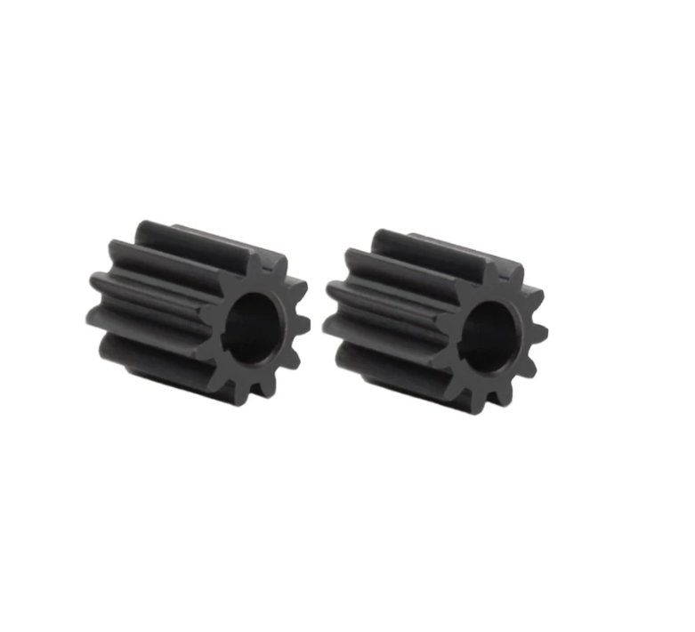
I apply this crowning modification to the pinion gears by a sweep cut in the solid model. The modification is small compared with the tooth size, but it changes the contact pattern significantly. The following figure shows a representative pinion gear used in the drive system.
After the crowning modification, I repeat the contact analysis for the 0.25° misalignment case. The maximum contact stress occurs on the large ring gear and is reduced to 400.46 MPa. This value is much lower than the allowable contact stress of 1500 MPa, and it is also much lower than the unmodified value of 1128.5 MPa. The maximum stress region moves inward from the tooth edge, which means that the edge effect is effectively controlled. The modified pinion gears therefore improve the load distribution and reduce the risk of scuffing, pitting, and abnormal wear.
| Condition | Maximum contact stress before modification | Maximum contact stress after modification | Reduction |
| α = 0.25° | 1128.5 MPa | 400.46 MPa | 64.5% |
The factor of safety against contact fatigue also improves substantially. I define the contact factor of safety as the allowable contact stress divided by the maximum contact stress.
$$FoS = \frac{[\sigma_H]}{\sigma_{H,\max}}$$
Before modification, the contact factor of safety at 0.25° misalignment is approximately 1.33. After modification, the contact factor of safety becomes approximately 3.75. This increase provides a much larger margin against uncertain loads, lubrication degradation, and manufacturing tolerance. The percentage reduction in maximum contact stress is calculated as follows.
$$\eta = \frac{1128.5 – 400.46}{1128.5} \times 100\% = 64.5\%$$
The root bending stresses after modification remain below the allowable values. At 0.25° misalignment, the large ring gear root stress is about 261.9 MPa before modification, and the pinion gear root stress is about 311.8 MPa. These values are already below the allowable root bending stresses of 562.5 MPa and 437.5 MPa, respectively. The crowning modification primarily improves contact stress and edge loading, while the root bending stress remains acceptable. Therefore, the combination of a 50 mm module, 23-tooth pinion gears, a 300-tooth large ring gear, and a properly designed crowning modification satisfies the strength requirements.
I also examine the load-sharing behavior among the pinion gears. In an ideal design, each pinion gear carries one third of the total torque on one side. In reality, manufacturing errors, backlash differences, support stiffness, and thermal effects can cause uneven load sharing. I introduce a load-sharing factor for each pinion gear.
$$T_i = \lambda_i \frac{T_{\max}}{n i}, \quad \sum_{i=1}^{n} \lambda_i = n$$
If one pinion gear carries a higher share, its contact stress and root bending stress increase. A robust design should therefore either use a flexible mounting arrangement, a torque equalizing system, or a conservative design margin. The crowning modification helps because it reduces the sensitivity of the contact pattern to small angular misalignments between the large ring gear and the pinion gears. However, I believe that load sharing should be verified during commissioning and monitored during operation.
The gear drive also has important manufacturing and integration issues. The large ring gear has a pitch diameter of 15000 mm and a module of 50 mm. This is a very large gear. Producing, heat treating, transporting, and installing such a ring gear is difficult. The pinion gears are much smaller, with a pitch diameter of 1150 mm and a face width of 580 mm, but they still require precise manufacturing because they transmit a high torque at low speed. The large ring gear is mounted on the side disc of the sector gate. This location may interfere with the side seal system. The side seal must prevent leakage between the side disc and the pier, and the space occupied by the large ring gear may make the seal arrangement more complex. I therefore consider the compatibility of the gear drive and the side seal to be a key engineering issue for future development.
Lubrication is another critical point. The gear drive operates as an open gear system at very low speed and very high torque. The lubricant must protect the pinion gears and the large ring gear against boundary friction, wear, and scuffing. A high-viscosity adhesive lubricant or an automatic lubrication system may be required. The lubricant should be applied to the meshing zone of the pinion gears and the large ring gear, and the lubricant condition should be checked periodically. Because the mechanism is hidden inside the pier, inspection and maintenance access must be planned carefully. I recommend inspection windows, removable covers, and remote condition monitoring where possible.
From a control point of view, each pinion gear can be driven by an electric motor and a multistage reducer. The drive system can use local control and remote central control. Local control should have the highest priority for maintenance and emergency operation. Each pinion gear should have an emergency operating device and a backup power unit. The control system should monitor motor current, torque, speed, and position. If one pinion gear loses load or becomes overloaded, the control system should alarm or stop the operation to prevent damage. Redundancy is important because the gate is a flood defense structure and must operate reliably during extreme weather.
I summarize the main feasibility criteria in the following table. The table compares the calculated or simulated stresses with the allowable values and shows whether the modified design passes each criterion.
| Criterion | Design value or simulated value | Allowable value | Result |
| Pinion gear root bending stress | 311.8 MPa at 0.25° | 437.5 MPa | Pass |
| Large ring gear root bending stress | 261.9 MPa at 0.25° | 562.5 MPa | Pass |
| Pinion gear contact stress before modification | 384.70 MPa at 0.25° | 1500 MPa | Pass but edge effect |
| Large ring gear contact stress before modification | 1128.5 MPa at 0.25° | 1500 MPa | Pass but high edge load |
| Large ring gear contact stress after modification | 400.46 MPa at 0.25° | 1500 MPa | Pass with margin |
| Contact factor of safety after modification | 3.75 | ≥ 1.0 | Pass |
I also evaluate the effect of the contact ratio on load sharing between teeth. The contact ratio of 1.71 means that the gear pair sometimes operates with a single pair of teeth in contact and sometimes with two pairs. The single-tooth contact condition is more severe for root bending stress. The two-tooth contact condition is better for load distribution but does not eliminate the need for crowning because the misalignment is a face-width problem rather than a profile problem. The crowning modification addresses the face-width load distribution, while the profile and module choices address the bending and contact strength.
The material selection is appropriate for the application. 20CrMnTi is a carburizing steel with good case hardness and core toughness. After carburizing and quenching, the tooth surface can resist contact fatigue and wear, while the core can support the bending load. The gear accuracy grade of 7 is reasonable for a large, slow-moving gate drive. Higher accuracy would improve load distribution but would also increase manufacturing cost. Because the speed is very low, dynamic effects are small. The main design drivers are torque, misalignment, contact stress, and edge loading, not dynamic vibration.
I consider the possibility of using more pinion gears per side. Increasing the number of pinion gears reduces the torque per pinion gear, but it also increases the number of contact points and the complexity of load sharing. In this study, I keep three pinion gears per side because this arrangement provides a balance between torque capacity and mechanical simplicity. The three pinion gears are distributed around the large ring gear so that the radial forces on the side disc are better balanced. Each pinion gear is supported by its own shaft and bearing system. The support stiffness must be high enough to prevent additional misalignment. If the support is too flexible, the pinion gears may tilt under load, which would worsen the edge contact. Therefore, the bearing housings and the pier structure must be designed as a stiff integrated system.
The finite element analysis uses a static load. In reality, the gate may experience variable water levels, wave action, and occasional impact loads. A dynamic amplification factor may be needed for extreme conditions. However, because the operating speed is extremely low, the dynamic amplification is expected to be small. The more important uncertainty is the actual misalignment caused by gate deflection. I use 0.25° as a conservative value for the analysis. If the actual misalignment is larger, the contact stress will increase. The crowning modification should be designed with enough margin to accommodate a range of misalignment angles. The analysis after modification shows that the maximum contact stress remains low at 0.25°, which suggests that the design has good tolerance to misalignment.
The pinion gears are the most highly loaded small components in the system. They must be manufactured with accurate tooth profiles, proper case depth, and good surface finish. The root fillet should be smooth to reduce stress concentration. The crowning should be applied uniformly along the face width. After manufacturing, the pinion gears should be inspected for tooth profile, lead, pitch, and runout. The large ring gear should also be inspected, but its size makes complete inspection more difficult. In situ alignment and contact pattern checks are therefore important during installation. The contact pattern should be centered on the tooth face under no load and should shift only slightly under load.
I believe the proposed gear drive is technically feasible, but it is not without challenges. The advantages are clear: the drive can be hidden inside the pier, the landscape impact is reduced, and the gate can rotate through a full circle for inspection. The disadvantages are also clear: the large ring gear is difficult to manufacture, the side seal arrangement may be complicated, and the load sharing among multiple pinion gears requires careful design. The gear drive is therefore most suitable for projects where landscape compatibility is a high priority and where the engineering team can manage the manufacturing and installation challenges.
For future work, I recommend several steps. First, the manufacturing process for the large ring gear should be studied in detail. This includes material forging, hobbing or milling, heat treatment, distortion control, and transportation. Second, the interface between the large ring gear and the side seal should be optimized. The gear and seal should not compete for the same space. Third, a full-scale or scaled model test should be performed to measure load sharing, contact pattern, and lubrication behavior. Fourth, a condition monitoring system should be developed to track torque, vibration, temperature, and backlash. Fifth, the control system should include redundancy and emergency operation to ensure reliable closure during extreme events.
In conclusion, I find that a gear-driven system using multiple pinion gears and a large ring gear is a feasible concept for a large sector gate. The design calculation gives a module of 50 mm, a pinion gear tooth number of 23, a large ring gear tooth number of 300, and a reduction ratio of approximately 13. The root bending stresses are below the allowable values. The contact stress is acceptable at zero misalignment, but it becomes edge-loaded at 0.25° misalignment because of gate deflection. A crowning modification on the pinion gears reduces the maximum contact stress from 1128.5 MPa to 400.46 MPa, moves the contact away from the tooth edge, and raises the contact factor of safety to about 3.75. The modified pinion gears therefore make the gear drive feasible from a strength point of view. The remaining challenges are the manufacture of the very large ring gear and the integration of the gear drive with the side seal system. With further development in these areas, the proposed gear drive can provide a compact, hidden, and landscape-friendly solution for large sector gates.
The analysis also shows the importance of considering system-level deformation in the design of pinion gears for large gates. A gear pair that performs well in a rigid test stand may fail in service if the supporting structure deflects and changes the mesh alignment. The pinion gears must be designed together with the gate structure, the side discs, the bearings, and the pier. The crowning modification is not an optional refinement in this application; it is a necessary measure to control edge loading. I therefore treat the modification as part of the baseline design rather than as a later correction.
Finally, I note that the gear drive concept can be adapted to other large gate types if the torque, speed, and misalignment conditions are properly evaluated. The same workflow can be used: calculate the torque per pinion gear, select the module from bending strength, check the contact stress, build a finite element model, introduce the expected misalignment, and apply a lead modification. The key is to keep the pinion gears and the large ring gear within allowable stress limits while maintaining a compact and hidden drive arrangement. The results of this study support continued development of the gear-driven sector gate and provide a reference for similar projects in the future.