
In the realm of mechanical engineering, the design and fabrication of gear shafts are critical for numerous transmission systems. A gear shaft, which integrates a gear and shaft necks into a single component, is ubiquitous in machinery, from automotive to industrial equipment. However, traditional design methods for gear shafts often involve repetitive modeling tasks, leading to inefficiencies and potential errors. To address this, we have developed a parametric design system that leverages Solid Edge and Visual Basic (VB) to automate and streamline the creation of gear shaft models. This system allows designers to quickly generate accurate three-dimensional digital models by inputting key parameters, thereby enhancing productivity and ensuring consistency. In this article, I will delve into the principles, methodologies, and implementation of this system, emphasizing its application in gear shaft design. Throughout, the term “gear shaft” will be frequently referenced to underscore its central role in our discussion.
The core of our approach lies in parameterization, where design variables drive the geometry of the gear shaft. By defining parameters such as gear module, number of teeth, shaft diameters, and lengths, we can dynamically update the model without manual redrawing. This is particularly beneficial for families of gear shafts with similar structures but varying dimensions. Our system is built upon Solid Edge, a powerful CAD software, and utilizes VB for secondary development through ActiveX Automation technology. This integration enables seamless communication between the user interface and Solid Edge’s modeling environment, facilitating automated design processes. The importance of gear shafts in mechanical systems cannot be overstated, as they transmit torque and motion efficiently, and our system aims to optimize their design phase.
To understand the foundation of our system, let’s explore the basic principles of VB development with Solid Edge. Solid Edge supports ActiveX Automation, which allows external programs to control its functions programmatically. In this setup, Solid Edge acts as a server, exposing objects, methods, and properties that can be accessed by a client application written in VB. Through the root Application object, we can manipulate lower-level objects such as parts, sketches, and features. This client-server architecture is enabled by including Solid Edge’s type libraries in the VB integrated development environment (IDE). By harnessing this technology, we can automate tasks like sketching, extrusion, and feature addition, which are essential for generating gear shaft models. The parametric design of gear shafts relies on this automation to modify dimensions and geometries based on user inputs.
When it comes to creating three-dimensional parametric models in Solid Edge via VB, we primarily employ two techniques. The first method involves editing variables within an existing model template. By predefining variables and relationships in a Solid Edge part file, we can use VB to alter these values and regenerate the model accordingly. This approach is straightforward and suitable for components with fixed shapes, such as standard gear shafts. However, for more complex or customizable gear shafts, we adopt the second method: programmatically invoking Solid Edge’s objects and methods to construct the model from scratch. This includes drawing profiles, creating features like extrusions and cuts, and applying patterns. Although this method requires more extensive coding, it offers greater flexibility in handling diverse gear shaft configurations. Our system utilizes the second method to ensure robust and adaptable design capabilities for gear shafts.
The design of a gear shaft typically involves two main components: the gear and the shaft necks. The gear portion often features involute teeth, which are standard in mechanical transmissions. To accurately model these teeth, we rely on mathematical equations for the involute curve. In our system, we establish a coordinate system with the gear center as the origin and the tooth symmetry line as the X-axis. The involute curve can be described using parametric equations. For any point on the involute, the coordinates can be calculated as follows:
$$ x = r_k \cos \delta_k $$
$$ y = r_k \sin \delta_k $$
where \( r_k \) is the radius at point \( k \), and \( \delta_k \) is an angle derived from gear parameters. Specifically, we define:
$$ \delta_k = \delta – (\theta_k – \theta) $$
$$ \delta = \frac{\pi}{2z} $$
$$ \theta_k = \text{inv} \alpha_k = \tan \alpha_k – \alpha_k $$
$$ \theta = \text{inv} \left( \frac{\pi}{9} \right) = \tan \left( \frac{\pi}{9} \right) – \frac{\pi}{9} $$
Here, \( z \) represents the number of teeth, and \( \alpha_k \) is the pressure angle. The radii involved include the addendum circle radius \( r_a \), base circle radius \( r_b \), dedendum circle radius \( r_f \), and pitch circle radius \( r \). These equations are implemented in VB to generate points along the involute, which are then connected to form the tooth profile. This mathematical foundation ensures precision in gear shaft design, critical for proper meshing and performance.
To generate the gear entity, our system follows a step-by-step process. First, based on user inputs from a custom interface, we create a cylindrical blank with a radius equal to the addendum circle radius and a height equal to the gear width. This is done using Solid Edge’s extrusion methods via VB. Next, if specified by the user, we apply chamfers to the gear edges using the Chamfers object’s AddEqualSetback method. Then, we compute the involute profile for a single tooth space by sampling multiple points (controlled by a variable \( n_E \)) and drawing lines between them. The more points used (higher \( n_E \)), the more accurate the involute approximation, albeit at the cost of increased computation time. This profile, combined with arcs for the addendum and dedendum circles, forms a closed contour for the tooth space. We then perform an extruded cut using the ExtrudedCutouts object’s AddFinite method to remove the tooth space from the cylindrical blank. Finally, we replicate this cut around the gear using a circular pattern based on the number of teeth, resulting in a fully formed gear. This automated process significantly speeds up gear shaft design.
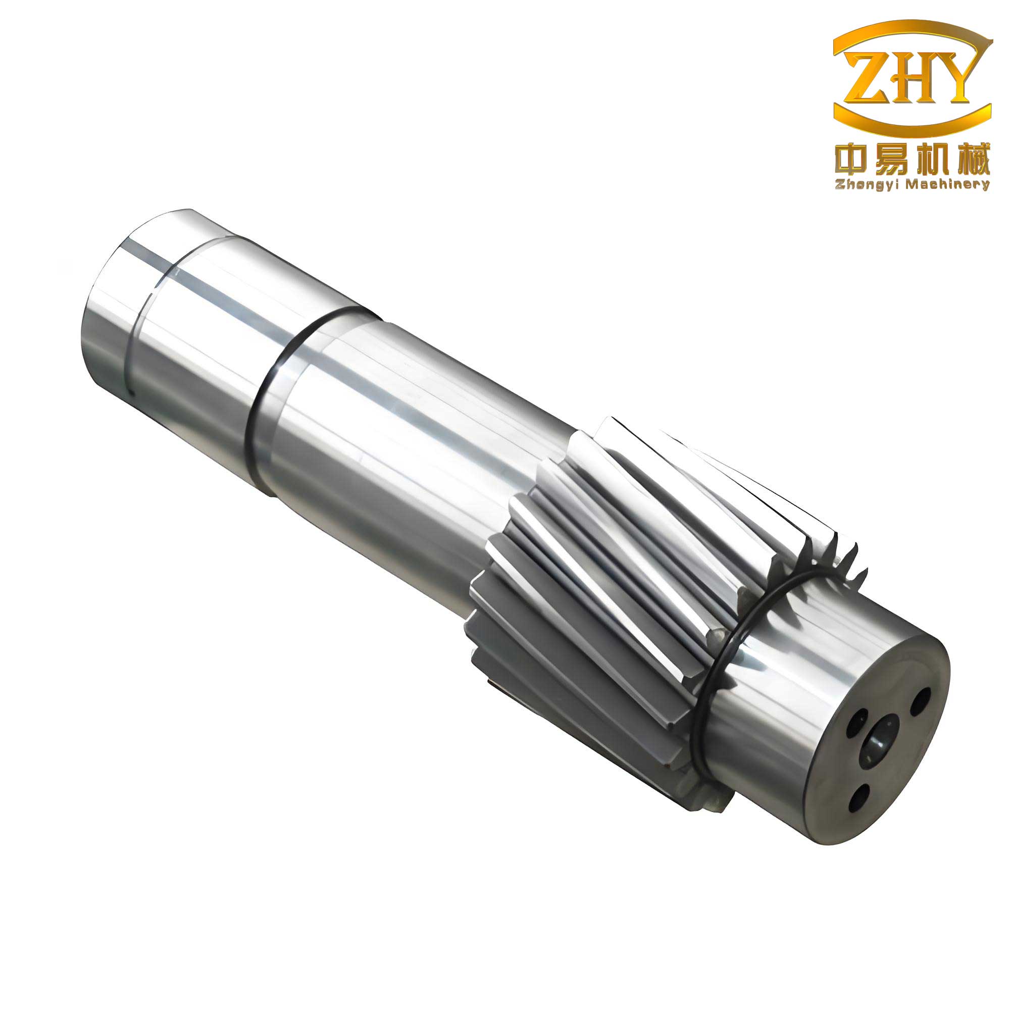
The shaft necks of a gear shaft are generally cylindrical or conical segments, often accompanied by features like keyslots, chamfers, and fillets. Our system handles these through a parametric approach. Users can input data for multiple shaft neck sections through a dedicated interface, including dimensions and optional features. The generation process iterates through each shaft neck section. For each section, we create a reference plane offset by the cumulative length of previous sections plus the gear width. On this plane, we draw a circle with a radius corresponding to the shaft diameter. Then, we extrude this circle to the specified length using the AddFiniteExtrudedProtrusion method. Subsequently, based on user selections, we add features such as chamfers (using AddEqualSetback), fillets, or keyslots. Keyslot dimensions are retrieved from a built-in database to ensure standardization. This iterative method allows for flexible design of gear shafts with varying numbers and configurations of shaft necks.
Our system’s user interface is designed for simplicity and efficiency. It includes forms for inputting gear parameters and shaft neck parameters. Below is a summary table of typical input parameters for a gear shaft:
| Parameter Type | Parameters | Description |
|---|---|---|
| Gear Parameters | Module, Number of Teeth, Face Width, Pressure Angle, Chamfer Size | Defines the gear geometry and optional features. |
| Shaft Neck Parameters | Diameter, Length, Chamfer Size, Keyslot Dimensions (if applicable) | Defines each shaft neck section and its features. |
For instance, when designing a gear shaft, users might input: module = 2 mm, number of teeth = 25, face width = 84 mm, and chamfer = 3×45° for the gear. For shaft necks, they could specify sections like: Section 1: diameter = 40 mm, length = 15 mm, chamfer = 2×45°; Section 2: diameter = 32 mm, length = 21 mm, chamfer = 2×45°; and so on. The system then processes these inputs to generate the complete gear shaft model. This tabular approach organizes data clearly, reducing errors in gear shaft design.
To illustrate the system’s capabilities, consider a practical example. Suppose we need a gear shaft with a spur gear having a module of 2, 25 teeth, and a width of 84 mm. The gear is flanked by shaft necks: on one side, two cylindrical sections with diameters of 40 mm and 32 mm, and lengths of 15 mm and 21 mm, respectively, both with 2×45° chamfers; on the other side, three cylindrical sections with diameters of 40 mm, 32 mm, and 28 mm, and lengths of 15 mm, 21 mm, and 60 mm, respectively, all with chamfers, and the last section including a keyslot of length 32 mm and axial position 24 mm. By entering these values into our system, the gear shaft model is automatically created in Solid Edge. The keyslot data is pulled from a standard database, ensuring compatibility with manufacturing standards. This example demonstrates how our parametric design system simplifies the creation of complex gear shafts.
The mathematical modeling of gear shafts involves several formulas beyond the involute equations. For instance, key gear dimensions can be calculated as follows:
$$ \text{Pitch diameter} = m \times z $$
$$ \text{Addendum diameter} = m \times (z + 2) $$
$$ \text{Dedendum diameter} = m \times (z – 2.5) $$
where \( m \) is the module and \( z \) is the number of teeth. These formulas are embedded in our VB code to compute necessary values during gear shaft generation. Additionally, for shaft necks, stress analysis formulas might be considered, though our focus is on geometric modeling. However, the system can be extended to include such calculations for comprehensive gear shaft design.
Our system offers several key advantages. First, it enables rapid and high-precision design of gear shaft digital models, reducing the time required from hours to minutes. Second, it democratizes design by not requiring advanced CAD skills from users; thus, engineers and technicians can easily create gear shafts. Third, it facilitates data management by storing design parameters in a knowledge base, which can be reused for future projects or for generating variant gear shafts. Fourth, the parametric nature allows for easy modifications; if a gear shaft needs resizing, users simply update the parameters, and the model regenerates automatically. This flexibility is crucial in iterative design processes common in mechanical engineering.
From an implementation perspective, the VB code integrates closely with Solid Edge’s API. We use objects like PartDocument, RefPlanes, Profiles, and Features to construct the gear shaft. Below is a simplified pseudocode snippet for generating a gear shaft:
1. Initialize Solid Edge application.
2. Create a new part document.
3. Input gear parameters via user form.
4. Generate gear blank cylinder.
5. Compute involute points and create tooth space cut.
6. Pattern tooth space around gear.
7. Input shaft neck parameters via user form.
8. For each shaft neck section:
   a. Create reference plane offset.
   b. Draw circle for shaft diameter.
   c. Extrude to length.
   d. Add chamfers, keyslots, etc., as needed.
9. Save and export the gear shaft model.
This structured approach ensures reliability and consistency in gear shaft production.
To further enhance the system, we have incorporated validation checks. For example, the system verifies that shaft neck diameters are logically ordered and that keyslot dimensions fit within the shaft sections. This prevents unrealistic gear shaft designs. Additionally, we plan to expand the system to handle other types of gears, such as helical or bevel gears, for more versatile gear shaft applications. The integration with finite element analysis (FEA) tools for stress evaluation is also a potential future development, making the gear shaft design process even more comprehensive.
In terms of performance, our system efficiently handles gear shafts with up to dozens of shaft neck sections. The use of VB ensures compatibility with Windows environments, and Solid Edge’s robust API supports complex operations. The parametric design of gear shafts not only improves efficiency but also enhances quality by minimizing human error. For instance, in traditional design, a minor mistake in dimension input could lead to a flawed gear shaft model, whereas our system automates calculations and geometry generation, ensuring accuracy.
Another aspect worth noting is the system’s adaptability to different design standards. Gear shafts are used worldwide, and dimensions may follow metrics like ISO or ANSI. Our system allows users to select standards, and the VB code adjusts calculations accordingly. For example, the addendum and dedendum coefficients might vary based on the standard. This flexibility makes the system suitable for global applications. Below is a table summarizing common gear shaft parameters across standards:
| Standard | Module Range (mm) | Pressure Angle (degrees) | Typical Gear Shaft Applications |
|---|---|---|---|
| ISO | 0.5 to 50 | 20 | Industrial machinery, automotive |
| ANSI | 0.25 to 25 | 20 or 14.5 | Power transmission, aerospace |
| JIS | 0.5 to 30 | 20 | Robotics, precision equipment |
By incorporating such data, our system supports diverse gear shaft design needs.
The economic benefits of this parametric design system are significant. By accelerating the design phase, companies can reduce time-to-market for products involving gear shafts. Moreover, the digital models can be directly used for CNC programming or 3D printing, streamlining manufacturing. In educational settings, the system serves as a tool for teaching gear shaft design principles, allowing students to experiment with parameters and observe outcomes in real-time. Thus, the impact extends beyond industrial applications.
From a technical depth perspective, the involute curve generation warrants further discussion. The variable \( n_E \) controls the number of points sampled on the involute. As \( n_E \) increases, the polyline approximation becomes smoother, but computation time rises. We typically set \( n_E = 50 \) for a balance between accuracy and speed. The coordinates for each point are computed using the earlier equations in a loop. In VB, this involves arrays and iterative calls to Solid Edge’s line-drawing methods. This meticulous approach ensures that the gear teeth on the gear shaft are geometrically correct, which is vital for smooth operation and noise reduction in transmissions.
Regarding shaft necks, the system handles both cylindrical and conical sections. For conical shaft necks, users input taper angles, and the VB code adjusts the profile accordingly. Features like grooves or threads can also be added through similar parametric methods. This versatility makes the system applicable to a wide range of gear shaft types, from simple to highly customized designs. The integration of a database for standard features like keyslots ensures compliance with industry norms, reducing the need for manual lookup.
In conclusion, our parametric design system for gear shafts, based on Solid Edge and VB, represents a significant advancement in CAD automation. By leveraging ActiveX Automation and mathematical modeling, we have created a tool that simplifies and accelerates the design of gear shafts. The system’s ability to handle both gear and shaft neck parametrization, along with features like chamfers and keyslots, makes it a comprehensive solution. Key benefits include improved efficiency, reduced errors, and enhanced accessibility for designers. As mechanical systems continue to evolve, the demand for efficient gear shaft design will grow, and our system is poised to meet that challenge. Future enhancements may include cloud integration for collaborative gear shaft design and advanced simulation capabilities. Ultimately, this work underscores the importance of parametric approaches in modern engineering, particularly for critical components like gear shafts.
To reiterate, the gear shaft is a fundamental element in power transmission, and our system empowers engineers to design it with unprecedented ease and precision. Through continuous refinement and expansion, we aim to set a new standard in parametric CAD for gear shafts and beyond.