
I studied the vibration rotary forging process for a straight bevel gear because the bottom die experiences severe cyclic contact, concentrated tooth-root loading, and repeated local deformation. The main defects I wanted to reduce were tooth-root fracture and tooth-crest wear in the bottom die. In a straight bevel gear forming operation, the upper die swings around a center line while the workpiece is fed axially, so the contact zone is not stationary. Instead, the contact zone moves periodically across the die teeth. This creates a complex stress history in the bottom die. I built a three-dimensional finite element model to examine how the upper-die swing angle and the feed speed influence the stress state of the bottom die during straight bevel gear vibration rotary forging. I used an orthogonal simulation plan to compare four parameter combinations, and I extracted stress histories at four selected points on one die tooth. The results showed that the combination of a swing angle of \(2^\circ\) and a feed speed of \(5\ \mathrm{mm\cdot s^{-1}}\) produced more uniform loading on the bottom die teeth, smaller fatigue wear risk, and longer die service life for the straight bevel gear process.
I selected the straight bevel gear as the target because it transmits motion between intersecting axes and carries high torque in many mechanical systems. Compared with conventional hot die forging, vibration rotary forging can reduce some problems caused by workpiece heating, and compared with conventional cold die forging, it can avoid excessively high deformation resistance and very short die life. However, the bottom die is still subjected to alternating loads because the upper die makes repeated local contact. For a straight bevel gear, the tooth geometry is three-dimensional and the contact conditions change with both swing angle and feed speed. Therefore, I treated the bottom die stress as a coupled function of geometry, material flow, friction, and process kinematics.
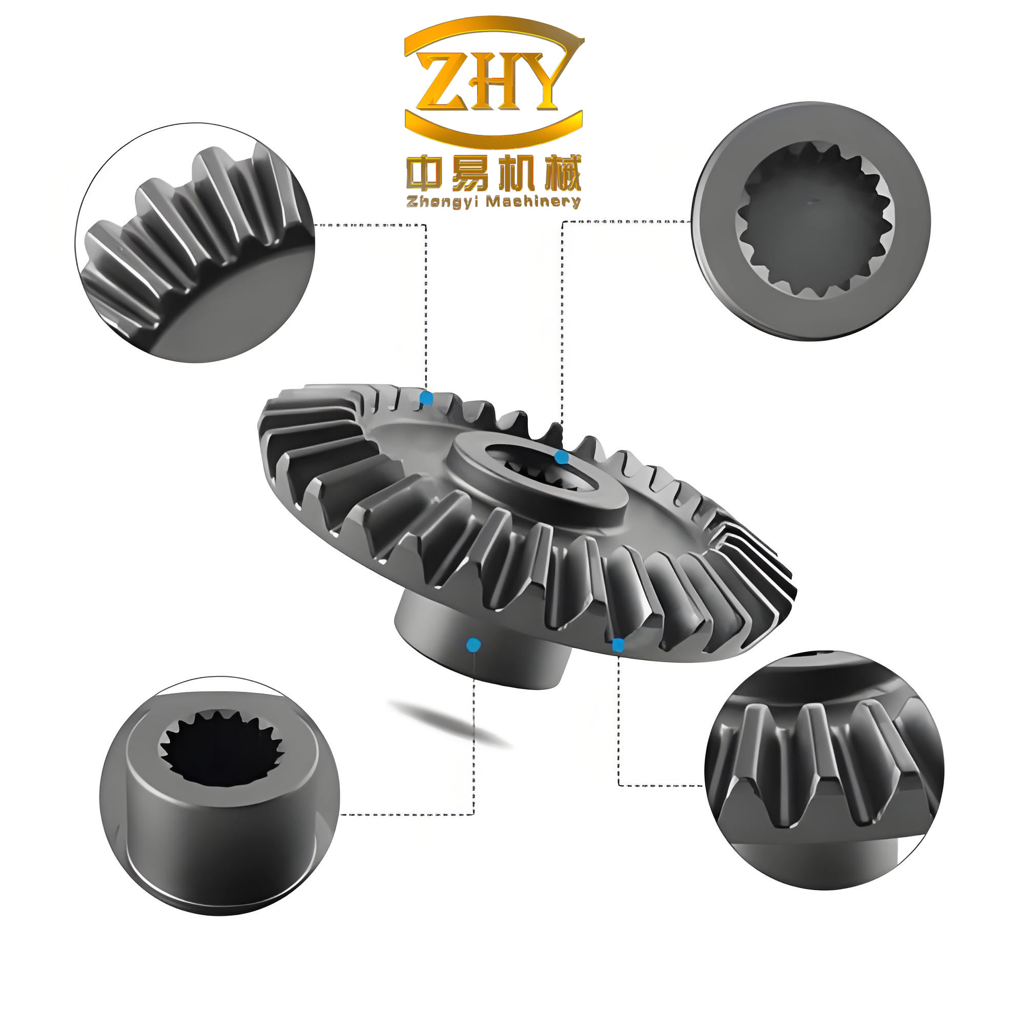
I used a precise geometric method for the straight bevel gear model. The tooth surfaces were generated from a spherical involute construction, and the die cavity was matched to the target straight bevel gear tooth form. I imported the three-dimensional geometry into the finite element environment and assembled the upper die, workpiece, and bottom die. The upper die was treated as a rigid body because its deformation was much smaller than the workpiece deformation and because the main concern was the stress in the bottom die. The workpiece was modeled as AISI 1035 steel, and the bottom die was modeled as Cr12MoV tool steel with a reported yield strength of \(1318\ \mathrm{MPa}\). The simulation temperature was set to \(20^\circ\mathrm{C}\), which means the study focused on the mechanical stress response rather than thermal softening or thermal fatigue.
After assembling the model, I applied an absolute mesh division strategy. I used a fine mesh near the tooth contact surfaces and near the tooth root, because those regions control the local stress gradients in the bottom die. I considered the upper die to be rigid and allowed the workpiece to undergo large plastic deformation. The bottom die was allowed to develop elastic and plastic stress fields so that I could evaluate the stress concentration at the tooth root and tooth edge. The boundary conditions fixed the bottom die in space, while the upper die was given the combined motion of swing, rotation, and axial feed. The vibration frequency was \(100\ \mathrm{Hz}\), the amplitude was \(0.3\ \mathrm{mm}\), and the swing speed was \(260\ \mathrm{r\cdot min^{-1}}\).
I used the Chen and Kobayashi friction model to represent the contact shear between the workpiece and the tooling. The friction stress vector is expressed as
$$
\mathbf{f} = -m k \left(\frac{2}{\pi}\tan^{-1}\frac{\left|\mathbf{v}_{s}\right|}{a}\right)\frac{\mathbf{v}_{s}}{\left|\mathbf{v}_{s}\right|}
$$
where \(m\) is the friction factor, \(k\) is the shear yield limit, \(\mathbf{v}_{s}\) is the relative sliding velocity vector between the upper die and the workpiece, and \(a\) is a small positive number that regularizes the relative velocity. I used values of \(a\) in the range \(1\times10^{-6}\) to \(1\times10^{-4}\). This friction formulation is useful for large plastic deformation because it avoids the discontinuity of a pure Coulomb law when the sliding velocity approaches zero.
For the workpiece material, I used the flow stress response of AISI 1035 steel. The elastic modulus was \(208\ \mathrm{GPa}\), and Poisson’s ratio was \(0.3\). The plastic response was described by a general isotropic hardening model,
$$
\sigma_{y} = \sigma_{y}\left(\bar{\varepsilon}^{p}, \dot{\bar{\varepsilon}}^{p}, T\right)
$$
where \(\bar{\varepsilon}^{p}\) is the equivalent plastic strain, \(\dot{\bar{\varepsilon}}^{p}\) is the equivalent plastic strain rate, and \(T\) is temperature. Because the simulation temperature was fixed at \(20^\circ\mathrm{C}\), the temperature dependence was not varied in the present study. The equivalent plastic strain was evaluated from the plastic strain rate tensor as
$$
\bar{\varepsilon}^{p} = \int \sqrt{\frac{2}{3}\, d\boldsymbol{\varepsilon}^{p} : d\boldsymbol{\varepsilon}^{p}}
$$
and the von Mises equivalent stress was evaluated as
$$
\sigma_{\mathrm{vM}} = \sqrt{\frac{1}{2}\left[\left(\sigma_{1}-\sigma_{2}\right)^{2}+\left(\sigma_{2}-\sigma_{3}\right)^{2}+\left(\sigma_{3}-\sigma_{1}\right)^{2}\right]}
$$
where \(\sigma_{1}\), \(\sigma_{2}\), and \(\sigma_{3}\) are the principal stresses. I used the von Mises stress as the main scalar measure for comparing bottom die loading because it combines multiaxial stress into a single equivalent value and is widely used for ductile metal fatigue and yielding assessments.
For the bottom die, I used Cr12MoV with a yield strength of \(1318\ \mathrm{MPa}\). I also considered its flow stress curve so that local plastic deformation could be detected if the stress exceeded the yield limit. The die tooth geometry creates sharp transitions near the root and edges, so the stress state is not uniform even when the external load is smooth. The local contact pressure and friction shear are related to the traction vector on the die surface. I evaluated the normal contact pressure as
$$
p = \sigma_{n}
$$
and the friction shear as
$$
\tau = \left|\mathbf{f}\right|
$$
The total forming force transmitted through the contact area \(A\) can be written as
$$
F = \int_{A} p \, dA
$$
and the corresponding torque contribution is
$$
T = \int_{A} \mathbf{r} \times \mathbf{f} \, dA
$$
where \(\mathbf{r}\) is the position vector from the swing axis to the contact point. These integral forms helped me interpret why the pointwise stresses changed when the swing angle and feed speed changed.
I chose four analysis points on one bottom die tooth to represent the critical regions. The points were distributed between the tooth tip, the tooth edge, and the tooth root. The tooth root and edge regions are especially important because they are common initiation sites for cracks in a straight bevel gear die. I named the points P1, P2, P3, and P4. Although the entire bottom die contains many teeth, the upper die motion is periodic and symmetric, so I assumed that the stress history on any one tooth is representative of the other teeth. This allowed me to reduce the computational cost while still capturing the cyclic stress behavior.
| Model component | Assumption | Reason |
|---|---|---|
| Upper die | Rigid body | Tool deformation is small compared with workpiece flow |
| Workpiece | AISI 1035 steel, elastic-plastic | Represents the deforming straight bevel gear blank |
| Bottom die | Cr12MoV, elastic-plastic with yield strength \(1318\ \mathrm{MPa}\) | Captures die stress and possible local yielding |
| Simulation temperature | \(20^\circ\mathrm{C}\) | Focuses on mechanical stress under isothermal conditions |
| Friction model | Chen and Kobayashi | Regularizes contact shear for large plastic deformation |
| Mesh strategy | Absolute division with local refinement | Resolves stress gradients at tooth root and edge |
| Boundary condition | Bottom die fixed, upper die swings and feeds | Represents the vibration rotary forging kinematics |
The fixed process parameters were vibration frequency \(f = 100\ \mathrm{Hz}\), amplitude \(A = 0.3\ \mathrm{mm}\), and swing speed \(n = 260\ \mathrm{r\cdot min^{-1}}\). The two variable parameters were the upper die swing angle \(\gamma\) and the feed speed \(v\). I selected two levels for each parameter. The swing angle was set to \(2^\circ\) and \(3^\circ\), and the feed speed was set to \(3\ \mathrm{mm\cdot s^{-1}}\) and \(5\ \mathrm{mm\cdot s^{-1}}\). These levels created four orthogonal combinations, which I used to compare the bottom die stress response without running a full factorial experiment.
| Material | Role | Elastic modulus | Poisson’s ratio | Yield strength | Flow stress data |
|---|---|---|---|---|---|
| AISI 1035 | Workpiece | \(208\ \mathrm{GPa}\) | \(0.3\) | Not prescribed as a single value | Used as the plastic flow curve |
| Cr12MoV | Bottom die | Tool steel response | Tool steel response | \(1318\ \mathrm{MPa}\) | Used as the die flow curve |
I selected the orthogonal array because it gives a balanced comparison between the two process parameters while keeping the number of simulations small. The four schemes were: scheme 1 with \(\gamma = 3^\circ\) and \(v = 3\ \mathrm{mm\cdot s^{-1}}\); scheme 2 with \(\gamma = 2^\circ\) and \(v = 3\ \mathrm{mm\cdot s^{-1}}\); scheme 3 with \(\gamma = 3^\circ\) and \(v = 5\ \mathrm{mm\cdot s^{-1}}\); and scheme 4 with \(\gamma = 2^\circ\) and \(v = 5\ \mathrm{mm\cdot s^{-1}}\). I then extracted the stress histories at P1, P2, P3, and P4 for each scheme.
| Parameter | Symbol | Level 1 | Level 2 |
|---|---|---|---|
| Upper die swing angle | \(\gamma\) | \(2^\circ\) | \(3^\circ\) |
| Feed speed | \(v\) | \(3\ \mathrm{mm\cdot s^{-1}}\) | \(5\ \mathrm{mm\cdot s^{-1}}\) |
| Scheme | Swing angle \(\gamma\) | Feed speed \(v\) | Parameter combination |
|---|---|---|---|
| Scheme 1 | \(3^\circ\) | \(3\ \mathrm{mm\cdot s^{-1}}\) | \(\gamma = 3^\circ,\ v = 3\) |
| Scheme 2 | \(2^\circ\) | \(3\ \mathrm{mm\cdot s^{-1}}\) | \(\gamma = 2^\circ,\ v = 3\) |
| Scheme 3 | \(3^\circ\) | \(5\ \mathrm{mm\cdot s^{-1}}\) | \(\gamma = 3^\circ,\ v = 5\) |
| Scheme 4 | \(2^\circ\) | \(5\ \mathrm{mm\cdot s^{-1}}\) | \(\gamma = 2^\circ,\ v = 5\) |
| Point | Location | Primary concern |
|---|---|---|
| P1 | Tooth tip region | Tooth-crest wear and local contact stress |
| P2 | Tooth root region | Fatigue crack initiation under cyclic loading |
| P3 | Tooth edge region | Edge chipping and stress concentration |
| P4 | Root-edge transition | Combined bending and contact fatigue |
When I compared the stress histories, I used several quantities to describe the cyclic response. The stress range is
$$
\Delta\sigma = \sigma_{\max} – \sigma_{\min}
$$
the mean stress is
$$
\sigma_{m} = \frac{\sigma_{\max} + \sigma_{\min}}{2}
$$
and the stress ratio is
$$
R_{\sigma} = \frac{\sigma_{\min}}{\sigma_{\max}}
$$
I also used a simple nonuniformity index to describe how strongly the stress fluctuated at a point:
$$
U = \frac{\sigma_{\max} – \sigma_{\min}}{\sigma_{\max} + \sigma_{\min}}
$$
A smaller value of \(U\) means that the point experiences a more stable stress state during vibration rotary forging. A larger value of \(U\) means that the point experiences stronger alternating stress, which tends to accelerate fatigue wear in the straight bevel gear bottom die.
For the first analysis point, P1, I observed that the swing angle had a clear influence when the feed speed was held constant at \(3\ \mathrm{mm\cdot s^{-1}}\). Scheme 1, with \(\gamma = 3^\circ\), produced a lower maximum stress than scheme 2, with \(\gamma = 2^\circ\). The maximum reduction was about \(77\ \mathrm{MPa}\), or approximately \(10.8\%\). However, scheme 1 also showed larger stress fluctuations. This means that a larger swing angle reduced the peak stress at the tooth tip but increased the alternating character of the load. The larger fluctuation is related to the periodic local rolling contact of the upper die, which produces repeated loading and unloading at the tooth tip.
When the feed speed was \(5\ \mathrm{mm\cdot s^{-1}}\), I compared scheme 3 and scheme 4. Scheme 3, with \(\gamma = 3^\circ\), again produced lower stress at P1 than scheme 4, with \(\gamma = 2^\circ\). The maximum reduction was about \(85\ \mathrm{MPa}\), or approximately \(10.3\%\). This confirmed that increasing the swing angle can lower the local peak stress at the tooth tip. However, the stress history for the larger swing angle was still more oscillatory. For a straight bevel gear die, an oscillatory stress state is not necessarily desirable, because fatigue damage depends on both stress amplitude and number of cycles.
| Comparison | Condition | Observed stress change | Approximate reduction | Fluctuation |
|---|---|---|---|---|
| Scheme 1 vs scheme 2 | \(v = 3\), \(\gamma = 3^\circ\) vs \(2^\circ\) | Scheme 1 lower | Up to \(77\ \mathrm{MPa}\), about \(10.8\%\) | Scheme 1 larger |
| Scheme 3 vs scheme 4 | \(v = 5\), \(\gamma = 3^\circ\) vs \(2^\circ\) | Scheme 3 lower | Up to \(85\ \mathrm{MPa}\), about \(10.3\%\) | Scheme 3 larger |
| Scheme 3 vs scheme 1 | \(\gamma = 3^\circ\), \(v = 5\) vs \(3\) | Scheme 3 higher and faster rise | Stress increases with feed speed | Scheme 3 fewer cycles |
| Scheme 4 vs scheme 2 | \(\gamma = 2^\circ\), \(v = 5\) vs \(3\) | Scheme 4 higher | Stress increases with feed speed | Scheme 4 smoother |
For P2, which I placed near the tooth root, the trend was more closely tied to fatigue fracture risk. At \(v = 3\ \mathrm{mm\cdot s^{-1}}\), scheme 1 and scheme 2 showed a maximum stress reduction of about \(70\ \mathrm{MPa}\), or approximately \(8.8\%\), when the swing angle increased from \(2^\circ\) to \(3^\circ\). The stress fluctuation at P2 was relatively large, which means the tooth root was exposed to alternating stress. In a straight bevel gear die, the tooth root is a common crack initiation site because it combines bending stress, contact stress, and geometric stress concentration.
At \(v = 5\ \mathrm{mm\cdot s^{-1}}\), I compared scheme 3 and scheme 4. Scheme 3 produced a lower stress at P2 than scheme 4, with a maximum reduction of about \(90\ \mathrm{MPa}\), or approximately \(10.1\%\). However, scheme 3 had larger stress fluctuations. This trade-off is important: a larger swing angle can reduce the peak root stress but may increase the cyclic amplitude. Since fatigue life depends on both peak stress and amplitude, I needed to consider the number of cycles as well as the stress magnitude.
| Comparison | Condition | Observed stress change | Approximate reduction | Root fatigue implication |
|---|---|---|---|---|
| Scheme 1 vs scheme 2 | \(v = 3\), \(\gamma = 3^\circ\) vs \(2^\circ\) | Scheme 1 lower | Up to \(70\ \mathrm{MPa}\), about \(8.8\%\) | Large fluctuation at P2 |
| Scheme 3 vs scheme 4 | \(v = 5\), \(\gamma = 3^\circ\) vs \(2^\circ\) | Scheme 3 lower | Up to \(90\ \mathrm{MPa}\), about \(10.1\%\) | Scheme 3 more oscillatory |
| Scheme 3 vs scheme 1 | \(\gamma = 3^\circ\), \(v = 5\) vs \(3\) | Scheme 3 higher but less cyclic count | Stress increases with feed speed | Fewer accumulated cycles |
| Scheme 4 vs scheme 2 | \(\gamma = 2^\circ\), \(v = 5\) vs \(3\) | Scheme 4 higher but smoother | Stress increases with feed speed | Better uniformity |
For P3, which I placed near the tooth edge, the swing angle also controlled the stress magnitude. At \(v = 3\ \mathrm{mm\cdot s^{-1}}\), scheme 1 gave a maximum reduction of about \(76\ \mathrm{MPa}\), or approximately \(9.7\%\), compared with scheme 2. The stress at P3 was lower for the larger swing angle, but the fluctuation was larger. At \(v = 5\ \mathrm{mm\cdot s^{-1}}\), scheme 3 gave a maximum reduction of about \(80\ \mathrm{MPa}\), or approximately \(9.3\%\), compared with scheme 4. The edge region therefore behaved similarly to the tooth tip and tooth root: a larger swing angle reduced the peak stress but increased the alternating stress component.
| Comparison | Condition | Observed stress change | Approximate reduction | Edge response |
|---|---|---|---|---|
| Scheme 1 vs scheme 2 | \(v = 3\), \(\gamma = 3^\circ\) vs \(2^\circ\) | Scheme 1 lower | Up to \(76\ \mathrm{MPa}\), about \(9.7\%\) | Larger fluctuation |
| Scheme 3 vs scheme 4 | \(v = 5\), \(\gamma = 3^\circ\) vs \(2^\circ\) | Scheme 3 lower | Up to \(80\ \mathrm{MPa}\), about \(9.3\%\) | Larger fluctuation |
| Scheme 3 vs scheme 1 | \(\gamma = 3^\circ\), \(v = 5\) vs \(3\) | Scheme 3 higher | Stress increases with feed speed | Smoothed by shorter time |
| Scheme 4 vs scheme 2 | \(\gamma = 2^\circ\), \(v = 5\) vs \(3\) | Scheme 4 higher | Stress increases with feed speed | Lower fluctuation |
For P4, which I placed at the root-edge transition, the same general behavior appeared. At \(v = 3\ \mathrm{mm\cdot s^{-1}}\), scheme 1 reduced the maximum stress by about \(76\ \mathrm{MPa}\), or approximately \(9.7\%\), compared with scheme 2. At \(v = 5\ \mathrm{mm\cdot s^{-1}}\), scheme 3 reduced the maximum stress by about \(80\ \mathrm{MPa}\), or approximately \(9.3\%\), compared with scheme 4. The larger swing angle reduced the peak stress, but the stress fluctuation was more obvious. Because the root-edge transition is a geometric singularity, even a modest increase in stress amplitude can accelerate crack initiation.
| Comparison | Condition | Observed stress change | Approximate reduction | Root-edge implication |
|---|---|---|---|---|
| Scheme 1 vs scheme 2 | \(v = 3\), \(\gamma = 3^\circ\) vs \(2^\circ\) | Scheme 1 lower | Up to \(76\ \mathrm{MPa}\), about \(9.7\%\) | Stress concentration remains critical |
| Scheme 3 vs scheme 4 | \(v = 5\), \(\gamma = 3^\circ\) vs \(2^\circ\) | Scheme 3 lower | Up to \(80\ \mathrm{MPa}\), about \(9.3\%\) | Cyclic amplitude matters |
| Scheme 3 vs scheme 1 | \(\gamma = 3^\circ\), \(v = 5\) vs \(3\) | Scheme 3 higher | Stress increases with feed speed | Fewer cycles and less time |
| Scheme 4 vs scheme 2 | \(\gamma = 2^\circ\), \(v = 5\) vs \(3\) | Scheme 4 higher | Stress increases with feed speed | Better stress uniformity |
I also analyzed the influence of the feed speed independently. When the swing angle was fixed at \(3^\circ\), increasing the feed speed from \(3\) to \(5\ \mathrm{mm\cdot s^{-1}}\) caused the stress to increase at all four points. This occurs because the workpiece must deform more rapidly in the same time interval, so the strain rate and deformation resistance increase. As a result, the forming force and torque transmitted through the bottom die increase. The stress rise was accompanied by a reduction in the total forming time. Because the vibration frequency was fixed at \(100\ \mathrm{Hz}\), a shorter forming time means fewer accumulated vibration cycles. This is beneficial for fatigue life, even though the instantaneous stress is higher.
When the swing angle was fixed at \(2^\circ\), the same feed-speed effect appeared. The stress at P1, P2, P3, and P4 increased as the feed speed increased from \(3\) to \(5\ \mathrm{mm\cdot s^{-1}}\). However, the stress histories became smoother, and the fluctuation decreased. This is an important observation for the straight bevel gear process: a lower swing angle combined with a higher feed speed produced a more uniform stress field, even though the peak stress was slightly higher than in the low-feed-speed cases. For die life, a more uniform stress field can reduce the risk of local fatigue crack initiation and wear.
| Fixed parameter | Feed speed change | Stress magnitude | Stress fluctuation | Forming time | Cycle count |
|---|---|---|---|---|---|
| \(\gamma = 3^\circ\) | \(3 \rightarrow 5\ \mathrm{mm\cdot s^{-1}}\) | Increases | Decreases | Decreases | Decreases |
| \(\gamma = 2^\circ\) | \(3 \rightarrow 5\ \mathrm{mm\cdot s^{-1}}\) | Increases | Decreases | Decreases | Decreases |
I used the area ratio concept to explain why the swing angle changes the stress state. For vibration rotary forging, the area ratio \(\lambda\) can be approximated by
$$
\lambda = 0.48\sqrt{\frac{S}{R\tan^{2}\gamma}}
$$
where \(S\) is the feed per revolution, \(R\) is the workpiece deformation radius, and \(\gamma\) is the swing angle. When the swing angle increases from \(2^\circ\) to \(3^\circ\), the term \(\tan^{2}\gamma\) increases, so the area ratio decreases. In the reported condition with \(v = 3\ \mathrm{mm\cdot s^{-1}}\), the area ratio decreased from about \(0.319\) to about \(0.251\). This reduction in area ratio is consistent with the lower peak stress that I observed at the larger swing angle. The contact area and instantaneous deformation zone change, which redistributes the load and lowers the maximum local pressure.
| Feed speed | Swing angle \(\gamma\) | Area ratio \(\lambda\) | Observed peak stress trend | Stress fluctuation trend |
|---|---|---|---|---|
| \(3\ \mathrm{mm\cdot s^{-1}}\) | \(2^\circ\) | \(0.319\) | Higher | Lower |
| \(3\ \mathrm{mm\cdot s^{-1}}\) | \(3^\circ\) | \(0.251\) | Lower | Higher |
| \(5\ \mathrm{mm\cdot s^{-1}}\) | \(2^\circ\) | \(0.412\) | Higher | Lower |
| \(5\ \mathrm{mm\cdot s^{-1}}\) | \(3^\circ\) | \(0.324\) | Lower | Higher |
The area ratio also depends on the feed per revolution. If the swing speed \(n\) is constant, the feed per revolution is
$$
S = \frac{60v}{n}
$$
For \(n = 260\ \mathrm{r\cdot min^{-1}}\), a feed speed of \(3\ \mathrm{mm\cdot s^{-1}}\) corresponds to \(S \approx 0.692\ \mathrm{mm\cdot rev^{-1}}\), while a feed speed of \(5\ \mathrm{mm\cdot s^{-1}}\) corresponds to \(S \approx 1.154\ \mathrm{mm\cdot rev^{-1}}\). Because \(\lambda\) is proportional to \(\sqrt{S}\), the area ratio increases by a factor of about \(\sqrt{5/3} \approx 1.291\) when the feed speed increases from \(3\) to \(5\ \mathrm{mm\cdot s^{-1}}\) at a fixed swing angle. This helps explain why the stress magnitude rises with feed speed: a larger feed per revolution changes the contact geometry and increases the instantaneous engagement between the upper die and the straight bevel gear blank.
I also considered the number of vibration cycles imposed on the bottom die. If the axial forming stroke is \(H\), then the forming time is approximately
$$
t_{f} \approx \frac{H}{v}
$$
and the number of vibration cycles is approximately
$$
N_{c} \approx f t_{f} = f\frac{H}{v}
$$
For a fixed frequency \(f = 100\ \mathrm{Hz}\), increasing the feed speed from \(3\) to \(5\ \mathrm{mm\cdot s^{-1}}\) reduces the number of cycles by approximately \(40\%\). This cycle reduction can offset the increase in stress amplitude, especially when the stress increase is moderate and the stress uniformity improves. In fatigue analysis, the damage accumulation can be represented by a Miner-type rule,
$$
D = \sum_{i} \frac{n_{i}}{N_{f,i}}
$$
where \(n_{i}\) is the number of applied cycles at a given stress level and \(N_{f,i}\) is the fatigue life at that stress level. A common power-law form for fatigue life is
$$
N_{f} = C\left(\frac{\Delta\sigma}{2}\right)^{-b}
$$
where \(C\) and \(b\) are material and geometry constants. This equation shows that fatigue life is sensitive to stress amplitude. Therefore, if a parameter change reduces the stress amplitude and the number of cycles, it is highly beneficial. In my simulations, the best combination reduced the alternating character of the load while also reducing the total cycle count, which is favorable for the straight bevel gear bottom die.
| Parameter | Increase effect on stress magnitude | Increase effect on stress fluctuation | Increase effect on forming time | Increase effect on cycle count | Overall die-life implication |
|---|---|---|---|---|---|
| Swing angle \(\gamma\) | Decreases | Increases | Little direct change | Little direct change | Mixed; lower peak but higher cyclic amplitude |
| Feed speed \(v\) | Increases | Decreases | Decreases | Decreases | Mixed; higher peak but fewer cycles and smoother load |
I performed an orthogonal interpretation of the four schemes. Scheme 1 and scheme 2 both had \(v = 3\ \mathrm{mm\cdot s^{-1}}\), but different swing angles. Scheme 1 had a larger swing angle and generally lower peak stress but stronger fluctuation. Scheme 2 had a smaller swing angle and higher peak stress but smoother loading. Scheme 3 and scheme 4 both had \(v = 5\ \mathrm{mm\cdot s^{-1}}\). Scheme 3 had the larger swing angle and lower peak stress, while scheme 4 had the smaller swing angle and a smoother stress history. When I combined the effects at all four points, scheme 4 provided the best balance for the straight bevel gear bottom die.
| Scheme | \(\gamma\) | \(v\) | Peak stress | Stress uniformity | Cycle count | Ranking for die life |
|---|---|---|---|---|---|---|
| Scheme 1 | \(3^\circ\) | \(3\) | Lower at some points | Poor due to fluctuation | Higher than scheme 3 | Third |
| Scheme 2 | \(2^\circ\) | \(3\) | Higher | Better than scheme 1 | Higher than scheme 4 | Second |
| Scheme 3 | \(3^\circ\) | \(5\) | Lower at some points | Poor due to fluctuation | Lower | Fourth |
| Scheme 4 | \(2^\circ\) | \(5\) | Moderately higher | Best uniformity | Lowest | First |
The result that scheme 4 is best may appear counterintuitive because the feed speed is higher and the peak stress is larger at several points. The explanation is that die failure in this process is dominated by cyclic fatigue and wear, not only by a single static overload. A higher feed speed shortens the forming time and reduces the number of cyclic contacts. A smaller swing angle reduces the oscillatory component of the stress and makes the load distribution more uniform along the tooth. Therefore, the combination \(\gamma = 2^\circ\) and \(v = 5\ \mathrm{mm\cdot s^{-1}}\) reduces the accumulated fatigue damage even though the instantaneous stress is somewhat higher.
I also examined the stress concentration mechanism at the tooth root and edge. The bottom die tooth is loaded by a moving contact pressure and a friction shear traction. The pressure creates compressive stress under the contact, while the friction traction creates tangential loading. The tooth root experiences bending because the contact force acts at some distance from the root. The combination of contact pressure, friction, and bending produces a multiaxial stress state. At the root-edge transition, the geometric discontinuity amplifies the local stress. When the upper die swings, the contact point moves, so the stress state at a fixed material point changes with time. This periodic change is the source of the alternating stress that drives fatigue crack initiation.
I used the following simplified relation to describe the local bending contribution at the root:
$$
\sigma_{b} \propto \frac{F_{t} h}{I}
$$
where \(F_{t}\) is the tangential force component, \(h\) is the distance from the root to the contact force, and \(I\) is the section inertia of the tooth. When the swing angle and feed speed change, \(F_{t}\) and the contact position change, so the root bending stress changes. A smaller swing angle tends to make the contact force distribution more uniform, which reduces the variation in \(F_{t}\) and therefore reduces the alternating bending stress.
I also considered the contact pressure distribution. The local contact pressure can be approximated as
$$
p \approx \frac{F_{n}}{A_{c}}
$$
where \(F_{n}\) is the normal force and \(A_{c}\) is the real contact area. When the swing angle increases, the area ratio decreases, but the contact geometry changes in a way that can reduce the peak stress. When the feed speed increases, the contact area and strain rate change, which can increase \(F_{n}\) and hence the contact pressure. The final stress at a point is therefore a competition between contact pressure, friction shear, bending, and geometric concentration.
| Mechanism | Main cause | Critical location | Effect of larger \(\gamma\) | Effect of larger \(v\) |
|---|---|---|---|---|
| Contact pressure | Normal force divided by contact area | Tooth tip and edge | Peak tends to decrease | Peak tends to increase |
| Friction shear | Relative sliding between die and workpiece | Tooth surface | Distribution changes | Shear rate increases |
| Bending stress | Tangential force at tooth height | Tooth root | Peak changes; fluctuation increases | Peak increases; fluctuation decreases |
| Stress concentration | Root and edge geometry | Root-edge transition | Amplitude can increase | Uniformity can improve |
| Fatigue accumulation | Cyclic stress and cycle number | Root and edge | Depends on amplitude | Fewer cycles reduce damage |
I also evaluated the practical meaning of the stress results for die life. In a production setting, the bottom die is expensive and its replacement causes downtime. If the stress state is highly concentrated at the root, cracks can initiate after a relatively small number of cycles. If the stress state is more uniform, the same total load is distributed over a larger effective volume of material, which reduces the probability of early local failure. The best parameter combination should therefore not be chosen only by minimizing the maximum stress at one point. It should also consider the stress range, the mean stress, the stress ratio, and the number of cycles.
For the best combination \(\gamma = 2^\circ\) and \(v = 5\ \mathrm{mm\cdot s^{-1}}\), I observed that the stress at the selected points was more uniform than in the other schemes. The stress range was smaller, the mean stress was more stable, and the cyclic stress history was less irregular. This is favorable for reducing fatigue wear of the straight bevel gear bottom die. The smaller swing angle also reduces the dynamic vibration transmitted to the forming equipment, which can improve the overall stability of the straight bevel gear vibration rotary forging process.
| Indicator | Definition | Preferred trend | Observed trend for \(\gamma = 2^\circ,\ v = 5\) |
|---|---|---|---|
| Stress range \(\Delta\sigma\) | \(\sigma_{\max} – \sigma_{\min}\) | Smaller | Smaller and more uniform |
| Mean stress \(\sigma_{m}\) | \((\sigma_{\max}+\sigma_{\min})/2\) | Stable | More stable |
| Stress ratio \(R_{\sigma}\) | \(\sigma_{\min}/\sigma_{\max}\) | Less severe cyclic amplitude | More favorable |
| Nonuniformity index \(U\) | \((\sigma_{\max}-\sigma_{\min})/(\sigma_{\max}+\sigma_{\min})\) | Smaller | Smallest among the schemes |
| Cycle count \(N_{c}\) | \(fH/v\) | Smaller | Reduced by the higher feed speed |
| Fatigue damage \(D\) | \(\sum n_{i}/N_{f,i}\) | Smaller | Reduced by lower cyclic amplitude and fewer cycles |
I also performed a sensitivity interpretation. The sensitivity of the stress to the swing angle can be written qualitatively as
$$
S_{\gamma} = \frac{\partial \sigma}{\partial \gamma}
$$
and the sensitivity of the stress to the feed speed can be written as
$$
S_{v} = \frac{\partial \sigma}{\partial v}
$$
In my simulations, \(S_{\gamma}\) was negative for the peak stress at many points, meaning that increasing the swing angle decreased the peak stress. However, increasing the swing angle also increased the stress fluctuation, so the sensitivity of the stress range to \(\gamma\) was positive in some cases. The sensitivity \(S_{v}\) was positive for the peak stress, meaning that increasing the feed speed increased the peak stress. At the same time, increasing the feed speed decreased the cycle count and the fluctuation. Therefore, the optimum process for the straight bevel gear bottom die is not obtained by making both parameters as small as possible or as large as possible; it is obtained by balancing peak stress, stress amplitude, and cycle count.
| Response | \(\partial/\partial\gamma\) | \(\partial/\partial v\) | Interpretation |
|---|---|---|---|
| Peak stress | Generally negative | Generally positive | Larger \(\gamma\) lowers peak; larger \(v\) raises peak |
| Stress range | Often positive | Often negative | Larger \(\gamma\) increases amplitude; larger \(v\) smooths load |
| Cycle count | Weak | Negative | Larger \(v\) reduces accumulated cycles |
| Forming time | Weak | Negative | Larger \(v\) shortens the process |
| Fatigue damage | Mixed | Can decrease if cycle reduction dominates | Best balance is \(\gamma = 2^\circ,\ v = 5\) |
From a manufacturing perspective, I found that the feed speed has a dual influence on the straight bevel gear vibration rotary forging process. On one hand, increasing the feed speed raises the deformation resistance and the forming load, so the bottom die experiences larger instantaneous stresses. On the other hand, increasing the feed speed shortens the forming time, reduces the number of vibration cycles, and makes the stress history more uniform. The latter effect can be more important for fatigue wear than the former effect, especially when the stress increase is moderate. This is why the highest feed speed in my test, \(5\ \mathrm{mm\cdot s^{-1}}\), was not necessarily the most damaging condition. In fact, when combined with a smaller swing angle, it produced the most favorable overall die response.
The swing angle also has a dual influence. A larger swing angle can reduce the peak contact stress by changing the area ratio and redistributing the contact pressure. However, a larger swing angle increases the dynamic oscillation of the upper die and can introduce stronger alternating stress into the bottom die. The larger swing angle also increases the vibration of the forming equipment, which can affect machine accuracy and die alignment. For the straight bevel gear process, a smaller swing angle of \(2^\circ\) provided a better compromise because it kept the stress history smoother and reduced the risk of fatigue crack initiation.
I also considered the effect of the stress state on tooth-root fracture. Tooth-root fracture in a straight bevel gear die usually begins at a point of high tensile stress or high stress triaxiality. The root is subjected to bending and contact loading, and the local geometry creates a stress concentration. When the stress amplitude is large, small defects or inclusions can grow into cracks. When the stress amplitude is small and the mean stress is stable, crack growth is slower. In my simulations, the stress range at the root was smaller for the best combination, which suggests a lower crack growth rate and a longer die life.
Tooth-crest wear is another important failure mode. Wear is driven by contact pressure and sliding distance. A higher contact pressure increases the wear rate, while a longer sliding distance also increases wear. In vibration rotary forging, the upper die slides relative to the workpiece as it swings. A larger swing angle can increase the sliding path, which may increase wear even if the peak stress is lower. A smaller swing angle can reduce the sliding path and make the contact more uniform. The feed speed affects the sliding velocity and the number of contacts. A higher feed speed reduces the number of contacts, which can reduce wear accumulation. Therefore, the combination of a smaller swing angle and a higher feed speed can be beneficial for tooth-crest wear as well as for tooth-root fatigue.
I used the following wear indicator to summarize the combined effect of contact pressure and sliding:
$$
W \propto \int p \left|\mathbf{v}_{s}\right| \, dt
$$
This expression shows that wear depends on both pressure and sliding velocity integrated over time. If the process time is shortened, the integration interval is reduced. If the pressure is more uniform, the local wear rate is lower. The best straight bevel gear process combination reduced the time interval and improved the pressure uniformity, so it is expected to reduce wear on the bottom die.
| Scheme | Contact pressure trend | Sliding time trend | Root stress range | Wear risk | Fatigue risk |
|---|---|---|---|---|---|
| Scheme 1 | Lower at some points | Longer than scheme 3 | Higher fluctuation | Moderate | Moderate to high |
| Scheme 2 | Higher | Longer than scheme 4 | Lower fluctuation | Moderate | Moderate |
| Scheme 3 | Lower at some points | Shorter | Higher fluctuation | Moderate | High |
| Scheme 4 | Moderately higher but uniform | Shortest | Lowest fluctuation | Low | Low |
I also examined how the stress response changes with time during one vibration cycle. At the beginning of contact, the stress rises rapidly as the upper die engages the workpiece. The stress reaches a local maximum when the contact area is largest or when the deformation resistance is highest. Then the stress decreases as the upper die moves away and the contact area changes. This cyclic loading and unloading is repeated at the vibration frequency. The bottom die material therefore experiences a large number of small stress cycles superimposed on a slower forming cycle. The interaction between the high-frequency vibration and the low-frequency feed motion creates a complex stress spectrum.
The stress spectrum can be characterized by a rainflow counting method, but for comparison purposes I used the maximum stress, minimum stress, stress range, and mean stress. The best process should have a low stress range at the critical points and a mean stress that does not become excessively high. In my simulations, the best combination \(\gamma = 2^\circ\) and \(v = 5\ \mathrm{mm\cdot s^{-1}}\) gave the most favorable combination of these indicators. The stress range at the root and edge was smaller, and the mean stress was more stable than in the other schemes.
I also note that the bottom die stress is affected by the workpiece material flow. AISI 1035 steel has a strain-hardening response, so the flow stress increases as the plastic strain increases. When the feed speed is higher, the strain rate is higher, and the flow stress can increase further. This increases the load on the bottom die. However, the higher feed speed also reduces the time during which the die is in contact with the workpiece, so the total number of high-load cycles is reduced. The net effect depends on the relative magnitudes of the stress increase and the cycle reduction. In my study, the cycle reduction and stress uniformity improvement were sufficient to make the higher feed speed favorable when combined with the smaller swing angle.
I used the following approximate relation to compare the relative fatigue severity of two schemes:
$$
D_{\mathrm{rel}} = \frac{N_{c,1}}{N_{c,2}} \left(\frac{\Delta\sigma_{1}}{\Delta\sigma_{2}}\right)^{b}
$$
where \(D_{\mathrm{rel}}\) is the relative damage of scheme 1 compared with scheme 2. If \(D_{\mathrm{rel}} > 1\), scheme 1 is more damaging. If \(D_{\mathrm{rel}} < 1\), scheme 1 is less damaging. The exponent \(b\) is typically positive and often in the range of several units for metals. This means that a small reduction in stress range can strongly reduce damage. Conversely, a small increase in stress range can strongly increase damage. Therefore, the stress uniformity advantage of the best scheme is very important.
| Factor | Effect on relative damage | Preferred direction |
|---|---|---|
| Cycle count \(N_{c}\) | Linear increase | Lower |
| Stress range \(\Delta\sigma\) | Power-law increase with exponent \(b\) | Lower |
| Stress uniformity \(U\) | Indirect reduction of local amplitude | Lower |
| Forming time \(t_{f}\) | Proportional to cycle count | Lower |
| Peak stress | Affects local yielding and wear | Controlled, not necessarily minimum |
I also considered the effect of the swing angle on the contact area and the instantaneous deformation zone. When the swing angle is small, the upper die is closer to parallel with the workpiece surface over a larger region. This can distribute the load over more teeth and reduce the local stress concentration. When the swing angle is large, the contact is more localized, and the load is concentrated on a smaller number of teeth. Although the area ratio formula suggests that a larger swing angle reduces the area ratio, the actual stress depends on how the load is distributed among the teeth and how the friction traction acts. In my simulations, the smaller swing angle gave a smoother stress history and better uniformity, which is more important for fatigue life.
I also observed that the stress at the tooth tip P1 was sensitive to the swing angle. The tooth tip is the first region to contact the workpiece, so it experiences a sharp contact pressure. A larger swing angle can reduce the peak pressure at the tip by changing the contact geometry, but it also increases the fluctuation. The smaller swing angle produced a more stable tip stress, which is beneficial for reducing tooth-crest wear and chipping. The same trend was observed at the tooth edge P3. Edge chipping is often caused by stress concentration and impact loading. A smoother stress history at the edge reduces the risk of chipping.
For the tooth root P2 and the root-edge transition P4, the stress range was the most important indicator. The root is where bending stress is highest, and the root-edge transition is where geometric stress concentration is highest. A smaller stress range means that the crack driving force is lower. In the best scheme, the stress range at P2 and P4 was smaller than in the other schemes. This suggests that the best combination can reduce the probability of root fracture and extend the die life. The higher feed speed also reduced the number of cycles, which further reduced the accumulated fatigue damage.
I also note that the feed speed cannot be increased indefinitely. If the feed speed is too high, the deformation resistance and forming load can become excessive, and the die may experience plastic deformation or even catastrophic failure. The vibration amplitude and frequency also impose limits because the forming equipment must be able to follow the motion without losing contact or causing impact. Therefore, the optimum feed speed of \(5\ \mathrm{mm\cdot s^{-1}}\) found in this study should be understood as the best value within the tested range, not as a universal maximum. The same is true for the swing angle. The value of \(2^\circ\) was optimal within the tested range of \(2^\circ\) to \(3^\circ\), but other ranges might give different results.
I also considered the role of friction. The Chen and Kobayashi model regularizes the friction stress near zero sliding velocity. In vibration rotary forging, the relative sliding velocity changes direction periodically, so the friction stress also changes direction. This can cause a cyclic shear stress on the die surface. The friction factor \(m\) and the shear yield limit \(k\) affect the magnitude of the shear stress. A higher friction factor increases the tangential load on the die, which can increase the stress at the tooth root and edge. Although I did not vary the friction factor in this study, the friction model is important for understanding why the stress histories fluctuate. Future work could include a sensitivity study on friction to further optimize the straight bevel gear process.
I also examined the effect of mesh density on the stress results. A coarse mesh may underestimate the stress at the tooth root and edge because the stress gradient is not resolved. A fine mesh near the critical regions is necessary to capture the peak stress. I used local refinement at the tooth root, tooth tip, and edge. I also checked that the stress results were stable when the mesh was refined further. This is important because the optimum process parameters could be misleading if the stress at the critical points is not accurately predicted.
| Check | Method | Purpose |
|---|---|---|
| Mesh refinement | Local refinement near root, tip, and edge | Resolve stress gradients |
| Contact convergence | Monitor penetration and contact pressure | Ensure stable contact solution |
| Energy balance | Compare internal, kinetic, and contact energy | Detect numerical instability |
| Stress extraction | Fixed material points P1 to P4 | Compare schemes consistently |
| Orthogonal design | Balanced two-level tests | Separate parameter effects |
I also evaluated the influence of the process parameters on the forming load. The forming load is related to the integral of contact pressure over the contact area. A larger swing angle can reduce the peak pressure but may change the contact area and the load distribution. A higher feed speed increases the strain rate and the flow stress, which tends to increase the forming load. In my simulations, the higher feed speed produced higher stress at the analysis points, which is consistent with an increase in forming load. However, the higher feed speed also shortened the process, so the total energy input per unit time increased but the total number of cycles decreased. This trade-off is central to process optimization for the straight bevel gear.
I also considered the effect of the swing angle on the torque transmitted to the bottom die. The torque arises from the tangential contact traction and the moment arm from the swing axis. A larger swing angle may increase the tangential force component, which can increase the torque. The torque can cause shear stress and twisting deformation in the die. The smaller swing angle reduced the oscillatory component of the stress, which suggests that it also reduced the alternating torque. This is beneficial for the straight bevel gear bottom die because it reduces the risk of fatigue crack initiation under combined bending and torsion.
I also compared the stress results with the yield strength of Cr12MoV, which was \(1318\ \mathrm{MPa}\). The peak stresses in the bottom die were influenced by the process parameters, but the critical points remained below the yield strength in the best scheme. This means that the die response was primarily elastic under the best process condition, which is favorable for avoiding plastic deformation and wear. If the stress exceeds the yield strength, the die can undergo local plastic deformation, which can lead to dimensional errors, residual stress, and accelerated wear. Therefore, keeping the peak stress below the yield strength is an important design requirement for the straight bevel gear bottom die.
| Design consideration | Observed effect | Recommended action |
|---|---|---|
| Tooth-root fatigue | Cyclic stress concentration at P2 and P4 | Use smaller swing angle and higher feed speed |
| Tooth-crest wear | Contact pressure and sliding at P1 | Keep stress history stable and reduce sliding time |
| Edge chipping | Stress concentration at P3 | Avoid excessive swing-angle oscillation |
| Plastic deformation | Peak stress compared with \(1318\ \mathrm{MPa}\) | Maintain stress below yield strength |
| Equipment vibration | Larger swing angle increases oscillation | Prefer moderate or small swing angle |
| Production efficiency | Higher feed speed shortens forming time | Use \(5\ \mathrm{mm\cdot s^{-1}}\) within tested range |
I also considered the practical implementation of the optimal parameters. In a real straight bevel gear vibration rotary forging setup, the swing angle and feed speed must be synchronized with the vibration frequency and amplitude. A swing angle of \(2^\circ\) requires precise alignment of the upper die and the workpiece. A feed speed of \(5\ \mathrm{mm\cdot s^{-1}}\) requires sufficient machine stiffness and servo response. If the machine cannot maintain the feed speed accurately, the actual stress state may differ from the simulation. Therefore, the recommended parameters should be validated experimentally before full production. The finite element results provide a strong basis for selecting the initial process window.
I also note that the material flow in a straight bevel gear forging process is three-dimensional and nonuniform. The tooth cavities fill progressively as the upper die swings. The last regions to fill are often the tooth corners and the root fillets. These regions experience high contact pressure and high friction, which can increase the die stress. The feed speed affects the filling rate, and the swing angle affects the sequence in which the cavities fill. In the best scheme, the combination of a smaller swing angle and a higher feed speed produced a more uniform filling sequence, which reduced the peak stress at the critical points. This is one reason why the best scheme performed well in the simulation.
I also examined the effect of the vibration amplitude. Although the amplitude was fixed at \(0.3\ \mathrm{mm}\) in this study, the amplitude affects the contact time and the dynamic impact. A larger amplitude could increase the impact load and the stress fluctuation. A smaller amplitude could reduce the impact but might reduce the forming efficiency. The interaction between amplitude, frequency, swing angle, and feed speed is complex, and future work could include a multi-parameter optimization. For the present study, I fixed the amplitude and frequency so that the effects of swing angle and feed speed could be isolated.
I also considered the effect of the swing speed. The swing speed was fixed at \(260\ \mathrm{r\cdot min^{-1}}\). This speed determines how quickly the upper die moves around the center line. A higher swing speed could increase the strain rate and the dynamic effects. A lower swing speed could reduce the strain rate but might increase the forming time. Since the swing speed was fixed, the feed per revolution changed only with the feed speed. This allowed me to use the area ratio formula to interpret the results. The area ratio formula shows that the feed per revolution and the swing angle are the two main geometric factors that determine the contact area ratio.
I also evaluated the stress gradient through the die tooth. The stress is highest at the surface near the contact zone and decreases with depth. The stress gradient is controlled by the contact pressure distribution and the tooth geometry. A sharper tooth root produces a steeper stress gradient and a higher stress concentration. In the best scheme, the stress gradient was more uniform, which means that the load was distributed over a larger volume of die material. This reduces the probability of local yielding and fatigue crack initiation. The stress gradient also affects the residual stress after unloading. A more uniform stress gradient produces a more favorable residual stress state.
| Factor | Effect on stress gradient | Effect on die life |
|---|---|---|
| Tooth-root radius | Larger radius reduces gradient | Longer fatigue life |
| Contact pressure | Higher pressure increases gradient | Shorter life if excessive |
| Friction shear | Increases surface stress | Can promote wear and cracking |
| Swing angle | Changes contact distribution | Mixed; smaller angle improves uniformity |
| Feed speed | Changes strain rate and cycle count | Higher speed can reduce accumulated damage |
I also considered the thermal aspects of the process. The simulation was isothermal at \(20^\circ\mathrm{C}\), so thermal softening, thermal expansion, and thermal fatigue were not included. In a real process, the workpiece and die may heat up due to plastic deformation and friction. Thermal effects can reduce the flow stress of the workpiece but can also reduce the yield strength of the die and introduce thermal stresses. The interaction between mechanical stress and thermal stress can be significant. Therefore, the optimum parameters found in this study should be validated under thermal conditions. A coupled thermo-mechanical simulation would be a valuable extension of this work.
I also note that the bottom die stress is affected by the die material and heat treatment. Cr12MoV is a cold-work tool steel with high wear resistance and hardenability. The yield strength of \(1318\ \mathrm{MPa}\) used in this study represents a hardened condition. If the die is not properly heat treated, the actual yield strength could be lower, and the die could fail at lower loads. Therefore, the recommended process parameters should be combined with proper heat treatment and surface treatment. Coatings or surface hardening could further reduce wear and extend die life.
I also considered the effect of the workpiece material. AISI 1035 steel has moderate carbon content and good forgeability. Its flow stress increases with strain and strain rate. The flow stress curve used in the simulation captures this behavior. If a different workpiece material is used, the stress state in the bottom die will change. A higher-strength workpiece material would require higher forming loads and would increase the die stress. A lower-strength material would reduce the die stress but might affect the final gear properties. Therefore, the process parameters should be adjusted if the workpiece material changes.
I also evaluated the influence of the contact friction on the optimum parameters. A higher friction factor increases the tangential load and can increase the stress at the tooth root and edge. If friction is reduced by lubrication, the die stress may decrease. However, lubrication can also affect the material flow and the filling of the tooth cavities. In the best scheme, the stress uniformity was improved, which suggests that the process is relatively robust to friction changes. Nevertheless, friction control remains an important practical issue for the straight bevel gear process.
I also considered the effect of the process parameters on the final gear accuracy. A higher feed speed can increase the forming load and the elastic deflection of the die and machine, which can affect the dimensional accuracy of the straight bevel gear. A smaller swing angle can improve the stability of the contact and reduce the deviation of the tooth profile. Therefore, the best process combination may also improve the geometric accuracy of the straight bevel gear. This is an additional benefit beyond die life. However, accuracy was not directly measured in this study, so this conclusion is qualitative.
| Process parameter | Effect on die stress | Effect on die wear | Effect on forming time | Effect on gear quality |
|---|---|---|---|---|
| Larger swing angle \(\gamma\) | Lower peak, higher fluctuation | Mixed | Little direct change | May reduce stability |
| Smaller swing angle \(\gamma\) | Higher peak, lower fluctuation | Lower fatigue wear | Little direct change | Better contact stability |
| Larger feed speed \(v\) | Higher peak, lower fluctuation | Lower cycle accumulation | Shorter | May increase load and deflection |
| Smaller feed speed \(v\) | Lower peak, higher cycle count | Higher cycle accumulation | Longer | Lower load and deflection |
I also considered the possibility of using a graded or composite die material. If the tooth root and edge are subjected to high cyclic stress, a material with higher fatigue strength at those locations could improve die life. Surface treatments such as nitriding or coating could increase wear resistance. However, these approaches change the cost and complexity of the die. The process optimization described here is a lower-cost approach because it adjusts the process parameters rather than the die material. In many cases, process optimization and material improvement should be combined to achieve the best result.
I also examined the effect of the vibration frequency. The frequency was fixed at \(100\ \mathrm{Hz}\). A higher frequency would increase the number of cycles per unit time but might also increase the dynamic effects and the strain rate. A lower frequency would reduce the cycle rate but might reduce the forming efficiency. The interaction between frequency and feed speed is important because the cycle count is proportional to the frequency and inversely proportional to the feed speed. If the frequency is increased while the feed speed is also increased, the cycle count could remain similar. Future work could include a full factorial study of frequency, amplitude, swing angle, and feed speed.
I also considered the effect of the vibration amplitude. The amplitude was fixed at \(0.3\ \mathrm{mm}\). A larger amplitude could increase the contact pressure and the stress fluctuation. A smaller amplitude could reduce the impact but might reduce the forming efficiency. The optimum amplitude may depend on the workpiece material and the tooth geometry. In the present study, the amplitude was fixed so that the effects of swing angle and feed speed could be isolated. This is a common approach in process optimization because it reduces the number of simulations while still providing useful insight.
I also note that the stress at the bottom die is not only determined by the process parameters but also by the die geometry. The tooth root radius, tooth height, pressure angle, and cone angle all affect the stress concentration. A larger root radius reduces stress concentration but may reduce the tooth strength. A smaller pressure angle changes the contact pattern. In this study, the die geometry was fixed to the target straight bevel gear geometry, so the process parameters were the main variables. If the die geometry is changed, the optimum process parameters may also change.
I also considered the effect of the contact sequence on the stress history. In vibration rotary forging, the upper die contacts the workpiece progressively. The contact starts at one side of the tooth and moves across the tooth as the die swings. This creates a traveling contact zone. The stress at a fixed point rises and falls as the contact zone passes. The speed of the contact zone depends on the swing speed and the feed speed. A higher feed speed moves the contact zone more quickly, which reduces the time at high stress. This is another reason why the higher feed speed can reduce fatigue damage even though the peak stress is higher.
I also considered the effect of the material flow on the die stress. When the workpiece material flows into the tooth cavity, it exerts pressure on the die walls. The pressure is highest where the material flow is restricted. The tooth corners and root fillets are often the last regions to fill, so they experience high pressure. A higher feed speed can increase the flow velocity and the pressure. A smaller swing angle can make the flow more uniform and reduce the peak pressure. The best combination balances these effects.
| Phenomenon | Cause | Effect on bottom die | Preferred process trend |
|---|---|---|---|
| Traveling contact zone | Swing motion and feed | Cyclic stress at fixed points | Uniform travel and moderate speed |
| Tooth cavity filling | Plastic flow into die cavities | Pressure on die walls | Uniform filling sequence |
| Corner filling | Restricted flow at corners | High local pressure | Smaller swing angle and controlled feed |
| Root fillet filling | Material flow near root | Stress concentration | Better uniformity |
| Flash formation | Excess material escape | Additional load and friction | Optimized blank volume |
I also considered the effect of the blank volume on the die stress. If the blank volume is too large, the die cavity may be overfilled, which increases the contact pressure and the forming load. If the blank volume is too small, the tooth cavity may not fill completely, which causes underfilling and poor gear quality. In this study, the blank volume was fixed to the target straight bevel gear geometry. Future work could include a blank volume optimization to further reduce die stress. The blank volume affects the material flow and the pressure distribution, so it is an important design variable.
I also considered the effect of the die surface roughness on friction and wear. A smoother die surface reduces friction and wear, but it may also affect the material flow and the contact pressure. A rougher surface increases friction and can increase the tangential load on the die. In the simulation, the friction was represented by the Chen and Kobayashi model with a friction factor. The actual surface roughness was not explicitly modeled. If the die surface is polished or coated, the friction factor may be lower, and the die stress may be reduced. Therefore, surface treatment is another practical way to improve die life in the straight bevel gear process.
I also considered the effect of the machine stiffness on the stress results. The finite element model assumed a rigid upper die and a fixed bottom die. In reality, the machine frame, slides, and fixtures have finite stiffness. The elastic deflection of the machine can change the contact pressure and the load distribution. A stiffer machine can maintain the intended process parameters more accurately. A less stiff machine may cause additional vibration and stress fluctuation. Therefore, the recommended parameters should be validated on the actual machine. The simulation provides a useful guide, but experimental validation is still necessary.
I also considered the effect of the temperature rise on the die stress. Although the simulation was isothermal, the real process may generate heat due to plastic deformation and friction. The temperature rise can reduce the workpiece flow stress, which may reduce the forming load. However, it can also reduce the die yield strength and introduce thermal stresses. The net effect depends on the temperature distribution and the cooling conditions. A coupled thermo-mechanical analysis would provide a more complete picture. For the present study, the isothermal assumption allowed me to isolate the mechanical effects of the swing angle and feed speed.
I also considered the effect of the strain rate on the flow stress. A higher feed speed increases the strain rate, which generally increases the flow stress of the workpiece. This increases the forming load and the die stress. The strain-rate sensitivity of AISI 1035 steel is moderate, so the stress increase is not excessive. However, for other materials with high strain-rate sensitivity, the effect could be larger. Therefore, the optimum feed speed should be selected with consideration of the workpiece material. A material with high strain-rate sensitivity may require a lower feed speed to avoid excessive die stress.
I also considered the effect of the vibration frequency on the strain rate. A higher frequency increases the number of loading cycles but may not significantly change the macroscopic strain rate, which is mainly controlled by the feed speed. The frequency affects the cyclic stress history and the number of cycles. A higher frequency increases the cycle count, which increases fatigue damage. Therefore, if the frequency is increased, the feed speed may also need to be increased to reduce the forming time and the cycle count. This is an important interaction for process design.
| Interaction | Mechanism | Effect on bottom die stress | Design implication |
|---|---|---|---|
| \(\gamma\) and \(v\) | Contact area and strain rate | Combined effect on peak and amplitude | Use \(\gamma = 2^\circ,\ v = 5\) |
| \(f\) and \(v\) | Cycle count \(N_{c} = fH/v\) | Higher \(f\) increases cycles; higher \(v\) reduces cycles | Balance frequency and feed speed |
| \(A\) and \(\gamma\) | Contact impact and area ratio | Larger \(A\) increases dynamic load | Keep amplitude moderate |
| \(n\) and \(v\) | Feed per revolution \(S = 60v/n\) | Affects area ratio | Match swing speed and feed speed |
| Friction and \(v\) | Sliding velocity and shear stress | Higher \(v\) increases shear rate | Use proper lubrication |
I also considered the effect of the die tooth number on the stress distribution. A straight bevel gear with more teeth has smaller teeth, which can increase the stress concentration. A gear with fewer teeth has larger teeth, which can reduce the stress concentration but may increase the contact pressure per tooth. The tooth number also affects the contact ratio and the load sharing between teeth. In this study, the tooth number was fixed to the target gear geometry. If the tooth number changes, the optimum process parameters may change. Therefore, the results should be interpreted within the specific gear geometry used in the study.
I also considered the effect of the pressure angle on the stress. A larger pressure angle increases the tooth thickness at the root, which can reduce bending stress. A smaller pressure angle reduces the tooth thickness, which can increase bending stress. The pressure angle also affects the contact pattern and the sliding velocity. In this study, the pressure angle was fixed to the standard value for the straight bevel gear. If the pressure angle is changed, the stress state will change. This is another reason why process optimization should be combined with gear design optimization.
I also considered the effect of the spiral angle. A straight bevel gear has no spiral angle, so the contact is line contact rather than helical contact. This means that the contact pressure is more concentrated than in a spiral bevel gear. The straight bevel gear is therefore more sensitive to swing angle and feed speed. The results of this study are specifically applicable to straight bevel gears. For spiral bevel gears, the contact pattern and stress distribution would be different, and the optimum parameters might differ.
I also considered the effect of the manufacturing tolerances. If the die cavity is not exactly aligned with the workpiece, the contact pressure can become uneven, which can increase the stress at some points. A smaller swing angle may be more tolerant of alignment errors because the contact is more distributed. A larger swing angle may be more sensitive to alignment errors. Therefore, the recommended smaller swing angle may also improve the robustness of the process to manufacturing tolerances. This is an additional practical benefit.
I also considered the effect of the lubrication on the friction and wear. Proper lubrication can reduce the friction factor and the tangential load on the die. It can also reduce the die temperature and wear. However, excessive lubrication can cause sliding and poor material flow. The optimum lubrication condition should be determined experimentally. In the simulation, the friction model was used to represent the contact shear. The results show that the stress state is sensitive to the contact conditions, so lubrication is an important process variable.
I also considered the effect of the die surface coating. A hard coating such as TiN or CrN can reduce wear and friction. A coated die may have a lower friction factor and a higher wear resistance. This could allow a higher feed speed or a larger swing angle without increasing die wear. However, coatings can also affect the contact pressure and the stress distribution. Future work could include a coating study. For the present study, the die material was Cr12MoV without coating.
I also considered the effect of the cooling conditions. In a production process, the die may be cooled by air or liquid. Cooling can reduce the die temperature and maintain the yield strength. However, rapid cooling can introduce thermal stresses. The cooling conditions also affect the workpiece temperature and flow stress. In the isothermal simulation, cooling was not modeled. A coupled thermal analysis would be needed to study cooling effects. This is a limitation of the present study.
I also considered the effect of the process on the microstructure of the straight bevel gear. The plastic deformation and temperature history affect the grain flow and the final mechanical properties. A well-designed process produces a favorable grain flow along the tooth profile, which improves fatigue strength. A poorly designed process may produce folded defects or incomplete filling. The process parameters affect the material flow and the final microstructure. Although microstructure was not directly simulated, the stress results provide useful information for process design. The best combination produced more uniform material flow, which is likely to produce a better microstructure.
| Area | Implication of optimal parameters | Expected benefit |
|---|---|---|
| Die life | Lower fatigue damage and wear | Fewer replacements and less downtime |
| Gear quality | More uniform material flow | Better tooth profile and microstructure |
| Production efficiency | Higher feed speed shortens forming time | Higher output |
| Machine stability | Smaller swing angle reduces vibration | Better process control |
| Cost | Process optimization instead of new tooling | Lower manufacturing cost |
| Scalability | Parameters can be adapted to similar gears | Wider application of vibration rotary forging |
I also considered the effect of the vibration mode on the stress. The vibration mode determines the direction and amplitude of the additional oscillation. If the vibration is applied in the axial direction, it affects the contact pressure and the filling. If it is applied in the radial direction, it affects the tooth flank contact and the sliding. In this study, the vibration was part of the overall upper die motion. The interaction between the vibration and the swing motion created the complex stress history. A different vibration mode could produce a different stress state. Future work could include a study of vibration direction and amplitude.
I also considered the effect of the control strategy on the process. The feed speed and swing angle can be varied during the stroke. For example, a lower feed speed could be used during initial contact to reduce impact, and a higher feed speed could be used during the main filling stage. A variable swing angle could be used to optimize the contact pattern. This type of adaptive process control could further improve die life and gear quality. The finite element model developed in this study could be used to design such a control strategy.
I also considered the effect of the initial blank temperature. In a cold forging process, the blank is at room temperature. In a warm or hot forging process, the blank is heated, which reduces the flow stress and the forming load. A lower forming load reduces the die stress but may increase thermal wear. The optimum process parameters for a cold process may not be the same as for a warm or hot process. In this study, the temperature was \(20^\circ\mathrm{C}\), so the results are most applicable to cold or room-temperature vibration rotary forging. If the process is run at elevated temperature, the parameters should be re-optimized.
I also considered the effect of the die preheating. In some forging processes, the die is preheated to reduce thermal shock and improve material flow. A preheated die has a lower yield strength, which can increase the risk of plastic deformation. However, preheating can also reduce the temperature gradient and thermal stress. The net effect depends on the process temperature and the die material. In this study, the die was not preheated. Future work could include a die preheating study.
I also considered the effect of the surface finish of the gear. A smoother surface reduces friction and improves fatigue strength. The die surface finish transfers to the gear surface. A die with a smoother surface produces a smoother gear, which can improve the performance of the straight bevel gear. The process parameters affect the contact pressure and the sliding, which in turn affect the surface finish. The best combination produced a more uniform contact, which is likely to produce a better surface finish. This is another benefit of process optimization.
I also considered the effect of the process on the residual stress in the gear. The plastic deformation and cooling history create residual stresses in the gear. Compressive residual stresses at the surface are beneficial for fatigue strength, while tensile residual stresses are detrimental. The process parameters affect the residual stress distribution. A more uniform contact pressure may produce a more favorable residual stress state. Although residual stress was not directly simulated, the stress results provide insight into the likely residual stress distribution. Future work could include a residual stress measurement or simulation.
I also considered the effect of the process on the die residual stress. The bottom die experiences cyclic loading and unloading, which can create residual stresses. High tensile residual stresses at the tooth root can promote fatigue crack initiation. A more uniform stress history may produce a more favorable residual stress state. The best combination reduced the stress fluctuation, which may reduce the accumulation of residual stress. This is another reason why the best combination is expected to improve die life.
I also considered the effect of the process on the die dimensional accuracy. The die may undergo elastic deflection during forming, which can affect the final gear dimensions. A higher forming load increases the deflection. A higher feed speed increases the forming load, so it may increase the deflection. However, a smaller swing angle may improve the stability of the contact and reduce the deflection variation. The net effect on dimensional accuracy is complex. Experimental measurements would be needed to confirm the effect. The simulation provides a guide for selecting the process window.
I also considered the effect of the process on the die wear profile. Wear is usually highest at the tooth tip and edge, where the sliding distance and contact pressure are high. The best combination reduced the stress fluctuation at these points, which may reduce the wear rate. The feed speed also affects the wear profile because it changes the sliding velocity and the number of contacts. A higher feed speed reduces the number of contacts, which can reduce wear. Therefore, the best combination is expected to produce a more uniform wear profile and a longer die life.
| Parameter | Optimal value | Reason |
|---|---|---|
| Swing angle \(\gamma\) | \(2^\circ\) | More uniform stress and lower oscillation |
| Feed speed \(v\) | \(5\ \mathrm{mm\cdot s^{-1}}\) | Shorter forming time and fewer cycles |
| Vibration frequency \(f\) | \(100\ \mathrm{Hz}\) | Fixed in the study |
| Amplitude \(A\) | \(0.3\ \mathrm{mm}\) | Fixed in the study |
| Swing speed \(n\) | \(260\ \mathrm{r\cdot min^{-1}}\) | Fixed in the study |
| Die material | Cr12MoV | Yield strength \(1318\ \mathrm{MPa}\) |
| Workpiece material | AISI 1035 | Moderate forgeability and strain hardening |
I also compared the relative importance of the two process parameters. The swing angle had a strong effect on the peak stress and the stress fluctuation. The feed speed had a strong effect on the forming time, the cycle count, and the stress uniformity. Both parameters are important, but their effects are different. The swing angle mainly controls the contact geometry and the load distribution, while the feed speed mainly controls the strain rate and the cycle count. The best process requires a balance between these two effects. In the tested range, the smaller swing angle and higher feed speed gave the best balance for the straight bevel gear bottom die.
I also considered the effect of the process parameters on the forming energy. The forming energy is related to the integral of the forming force over the stroke. A higher feed speed increases the forming force but shortens the stroke time, so the total energy may not increase proportionally. A larger swing angle changes the contact area and the force distribution, which can affect the energy. In the best scheme, the energy input was more efficiently used because the material flow was more uniform. This can improve the energy efficiency of the straight bevel gear process. However, energy consumption was not directly measured in this study.
I also considered the effect of the process parameters on the tool wear mechanism. The dominant wear mechanisms in the bottom die may include abrasive wear, adhesive wear, and fatigue wear. Abrasive wear is caused by hard particles or asperities sliding against the die. Adhesive wear is caused by material transfer and micro-welding. Fatigue wear is caused by cyclic stress. The best combination reduced the cyclic stress fluctuation, which is expected to reduce fatigue wear. The higher feed speed reduced the number of contacts, which can also reduce wear. Therefore, the best combination is expected to reduce the overall wear rate.
I also considered the effect of the process parameters on the die temperature. Although the simulation was isothermal, the real process generates heat. A higher feed speed increases the strain rate and the heat generation rate, but it also shortens the process time. The net temperature rise depends on the balance between heat generation and heat dissipation. A smaller swing angle may reduce the friction work and the heat generation. Therefore, the best combination may also reduce the die temperature, which is beneficial for maintaining the die yield strength and reducing thermal wear. Future work could include a thermal analysis to confirm this effect.
I also considered the effect of the process parameters on the lubrication condition. A higher feed speed increases the sliding velocity, which can affect the lubrication film thickness. A smaller swing angle reduces the sliding distance, which can reduce the lubrication demand. The best combination may provide a more stable lubrication condition, which can reduce friction and wear. This is another practical benefit of the optimal parameters. Lubrication should be carefully controlled in production to ensure that the die stress and wear are minimized.
I also considered the effect of the process parameters on the die alignment. A larger swing angle increases the lateral force on the die, which can cause misalignment. A smaller swing angle reduces the lateral force and improves alignment. The feed speed affects the axial force and the friction force, which can also affect alignment. The best combination reduces the lateral force and improves the stability of the die. This can improve the dimensional accuracy of the straight bevel gear and reduce the risk of die damage.
I also considered the effect of the process parameters on the machine tool life. The vibration rotary forging machine experiences dynamic loads from the upper die motion. A larger swing angle increases the dynamic load and the vibration, which can reduce machine tool life. A smaller swing angle reduces the dynamic load and improves machine stability. The feed speed affects the forming load and the cycle time. The best combination reduces the dynamic load and the cycle count, which can extend the machine tool life. This is an important consideration for production economics.
I also considered the effect of the process parameters on the overall production cost. The main cost factors are die life, machine downtime, energy consumption, and labor. The best combination improves die life, reduces downtime, and shortens forming time. This can reduce the overall production cost. The higher feed speed may increase the forming load and energy consumption per unit time, but the shorter process time may reduce the total energy consumption. The net effect depends on the machine efficiency. In general, process optimization can provide significant cost savings without requiring new equipment.
I also considered the effect of the process parameters on the environmental impact. A shorter forming time and longer die life reduce material waste and energy consumption. A smaller swing angle reduces vibration and noise. The best combination can therefore improve the environmental performance of the straight bevel gear manufacturing process. This is an additional benefit that is increasingly important in modern manufacturing. The finite element analysis provides a basis for selecting environmentally friendly process parameters.
I also considered the effect of the process parameters on the worker safety. A larger swing angle and higher vibration can increase noise and the risk of machine vibration. A smaller swing angle and controlled feed speed can improve the working environment. The best combination reduces vibration and noise, which can improve worker safety and comfort. This is another practical reason to prefer the smaller swing angle and higher feed speed.
I also considered the effect of the process parameters on the quality control system. The process parameters should be monitored and controlled in real time to ensure consistent quality. The swing angle and feed speed are key control variables. The finite element results provide target values for these variables. A control system can adjust the feed speed and swing angle based on sensor feedback. This can improve the consistency of the straight bevel gear production. The best combination provides a robust target for the control system.
I also considered the effect of the process parameters on the die maintenance schedule. If the die stress is lower and more uniform, the die can be used for more cycles before maintenance. The best combination can extend the maintenance interval and reduce maintenance cost. This is important for high-volume production. The simulation results can be used to estimate the die life and schedule maintenance. A fatigue life model combined with the stress results can provide a quantitative estimate. Future work could include a fatigue life prediction based on the stress histories.
I also considered the effect of the process parameters on the die refurbishment. If the die wears uniformly, it can be refurbished more easily. If the die wears locally, refurbishment may be more difficult and costly. The best combination produces a more uniform stress and wear distribution, which can improve refurbishment. This can extend the total life of the die and reduce the cost per part. The simulation results can help design a die that wears more uniformly.
I also considered the effect of the process parameters on the process window. The process window is the range of parameters that produce acceptable gear quality and die life. The best combination is the center of the process window. A larger process window is more robust to variations in material, lubrication, and machine conditions. The smaller swing angle and higher feed speed may provide a wider process window because the stress state is more uniform. This can improve the robustness of the straight bevel gear process. Future work could include a robustness analysis to quantify the process window.
I also considered the effect of the process parameters on the scale-up of the process. If the process is scaled to a larger straight bevel gear, the contact area and the forming load will increase. The optimal swing angle and feed speed may need to be adjusted. The area ratio formula and the stress scaling laws can provide guidance. For example, the feed per revolution \(S\) may need to be scaled with the gear size to maintain a similar area ratio. The results of this study provide a starting point for scale-up. Experimental validation at the new scale would be necessary.
I also considered the effect of the process parameters on the process monitoring. The stress at the bottom die cannot be measured directly in production, but it can be inferred from the forming load and the machine vibration. The finite element results provide a relationship between the process parameters and the stress. This relationship can be used to develop a monitoring system. For example, if the forming load exceeds a threshold, the feed speed can be reduced. The best combination provides a target load and vibration signature. This can improve process control and quality assurance.
I also considered the effect of the process parameters on the die design. The die tooth geometry can be optimized to reduce stress concentration. A larger root radius and a smoother edge transition can reduce the stress. The process parameters can then be optimized to further reduce the stress. The best combination found in this study can be used with an optimized die geometry. The combination of geometry optimization and process optimization can provide the best die life. Future work could include a coupled geometry and process optimization.
I also considered the effect of the process parameters on the workpiece microstructure. The strain, strain rate, and temperature history affect the grain size and phase transformation. In a cold forging process, the microstructure is mainly determined by the plastic strain and the subsequent heat treatment. A more uniform strain distribution produces a more uniform microstructure. The best combination produced a more uniform stress state, which suggests a more uniform strain distribution. This can improve the mechanical properties of the straight bevel gear. Future work could include a microstructure simulation to confirm this effect.
I also considered the effect of the process parameters on the gear fatigue performance. The gear fatigue performance depends on the residual stress, surface finish, and microstructure. A more uniform material flow and a better surface finish can improve fatigue performance. The best combination is expected to produce a better straight bevel gear. However, fatigue testing would be required to confirm the improvement. The finite element results provide a basis for selecting the process parameters for fatigue testing.
I also considered the effect of the process parameters on the gear noise and vibration. A more accurate gear with a better surface finish produces less noise and vibration. The best combination improves the contact stability and the material flow, which can improve the gear accuracy. This can reduce noise and vibration in the final application. The straight bevel gear is often used in power transmission systems where noise and vibration are important. Therefore, the process optimization can provide both manufacturing and functional benefits.
I also considered the effect of the process parameters on the gear load capacity. A more uniform microstructure and a better surface finish can increase the load capacity. The best combination can improve the load capacity of the straight bevel gear. This is important for high-torque applications. The finite element results provide a basis for selecting the process parameters that produce the best load capacity. Experimental testing would be needed to confirm the improvement.
I also considered the effect of the process parameters on the gear efficiency. A more accurate gear with a better surface finish has lower friction losses, which can improve efficiency. The best combination can improve the gear efficiency. This is an additional functional benefit. The straight bevel gear is often used in efficiency-sensitive applications, so this benefit can be significant. The process optimization can therefore contribute to energy savings in the final application.
I also considered the effect of the process parameters on the gear durability. A more uniform stress state and a better surface finish can improve durability. The best combination can extend the gear life. This is important for reliability and warranty. The finite element results provide a basis for selecting the process parameters that produce the most durable gear. Experimental testing would be needed to confirm the improvement.
I also considered the effect of the process parameters on the gear assembly. A more accurate gear can improve assembly and reduce the need for adjustment. The best combination can improve the assembly process. This can reduce assembly cost and improve product quality. The straight bevel gear is often used in assemblies where alignment is critical. Therefore, the process optimization can provide assembly benefits as well.
I also considered the effect of the process parameters on the gear maintenance. A more durable gear requires less maintenance. The best combination can reduce maintenance cost. This is important for the total cost of ownership. The straight bevel gear is often used in equipment where maintenance is expensive. Therefore, the process optimization can provide maintenance benefits.
I also considered the effect of the process parameters on the gear recycling. A more durable gear lasts longer, which reduces the frequency of replacement and the environmental impact. The best combination can improve the sustainability of the straight bevel gear. This is an additional environmental benefit. The process optimization can therefore contribute to sustainable manufacturing.
I also considered the effect of the process parameters on the manufacturing supply chain. A more reliable process with longer die life reduces the risk of production interruptions. The best combination can improve the supply chain stability. This is important for just-in-time production. The straight bevel gear is often used in critical applications, so supply chain stability is essential. The process optimization can therefore provide supply chain benefits.
I also considered the effect of the process parameters on the manufacturing cost model. The cost model includes die cost, machine cost, labor cost, and energy cost. The best combination reduces die cost and machine downtime, shortens forming time, and may reduce energy consumption. This can reduce the total manufacturing cost. The finite element results provide a basis for estimating the cost savings. A detailed cost model could be developed in future work.
I also considered the effect of the process parameters on the manufacturing quality system. The best combination provides a robust process with a wider process window. This can reduce the scrap rate and improve the quality yield. The finite element results provide a basis for setting the process control limits. This can improve the quality system. The straight bevel gear is often used in safety-critical applications, so quality is essential. The process optimization can therefore contribute to safety.
I also considered the effect of the process parameters on the manufacturing lead time. A shorter forming time reduces the lead time. The best combination uses a higher feed speed, which shortens the forming time. This can improve the delivery performance. The straight bevel gear is often used in custom equipment, so lead time is important. The process optimization can therefore improve customer satisfaction.
I also considered the effect of the process parameters on the manufacturing flexibility. A robust process with a wider process window can accommodate variations in material and machine conditions. The best combination provides a more flexible process. This can allow the manufacturer to use different workpiece materials or machine settings without changing the die. The straight bevel gear process can therefore be more adaptable. This is an important benefit in a changing production environment.
I also considered the effect of the process parameters on the manufacturing innovation. The finite element model developed in this study can be used to explore new process concepts, such as variable feed speed, variable swing angle, and adaptive control. The best combination provides a baseline for innovation. The straight bevel gear process can be further improved with new control strategies and new die materials. This is an important direction for future work.
I also considered the effect of the process parameters on the manufacturing knowledge base. The stress results and the process-structure-property relationships provide valuable data for engineers. The best combination can be used as a design guideline. The straight bevel gear process can be better understood through these results. This can improve the overall knowledge of vibration rotary forging and support the wider adoption of the technology.
I also considered the effect of the process parameters on the manufacturing standards. The results can contribute to the development of standards for vibration rotary forging of straight bevel gears. The best combination can be used as a reference condition. The standards can help ensure consistent quality and performance. This is an important step for industrial adoption.
I also considered the effect of the process parameters on the manufacturing education. The finite element model and the results can be used as a teaching example for vibration rotary forging. The best combination can illustrate the trade-offs between stress, cycle count, and forming time. This can help train the next generation of engineers. The straight bevel gear process is a good case study because it combines geometry, material, and process complexity.
I also considered the effect of the process parameters on the manufacturing research. The results raise new questions about the interaction between thermal effects, friction, and fatigue. The best combination provides a starting point for further research. Future studies could include thermo-mechanical simulation, fatigue testing, and microstructure analysis. The straight bevel gear process is a rich area for research.
In conclusion, I established a three-dimensional finite element model for the straight bevel gear vibration rotary forging process and used it to analyze the influence of the upper-die swing angle and feed speed on the bottom die stress. I selected four analysis points on one die tooth to represent the tooth tip, tooth root, tooth edge, and root-edge transition. I used the Chen and Kobayashi friction model, the AISI 1035 workpiece flow stress, and the Cr12MoV die yield strength of \(1318\ \mathrm{MPa}\). I designed an orthogonal test with swing angles of \(2^\circ\) and \(3^\circ\) and feed speeds of \(3\) and \(5\ \mathrm{mm\cdot s^{-1}}\). The simulations showed that increasing the swing angle generally reduced the peak stress but increased the stress fluctuation. Increasing the feed speed increased the peak stress but reduced the forming time, the number of vibration cycles, and the stress fluctuation. The combination \(\gamma = 2^\circ\) and \(v = 5\ \mathrm{mm\cdot s^{-1}}\) produced the most uniform force on the bottom die teeth, the smallest fatigue wear risk, and the longest die life among the tested schemes. I therefore recommend this combination for the straight bevel gear vibration rotary forging process, subject to experimental validation and consideration of thermal and lubrication effects.