
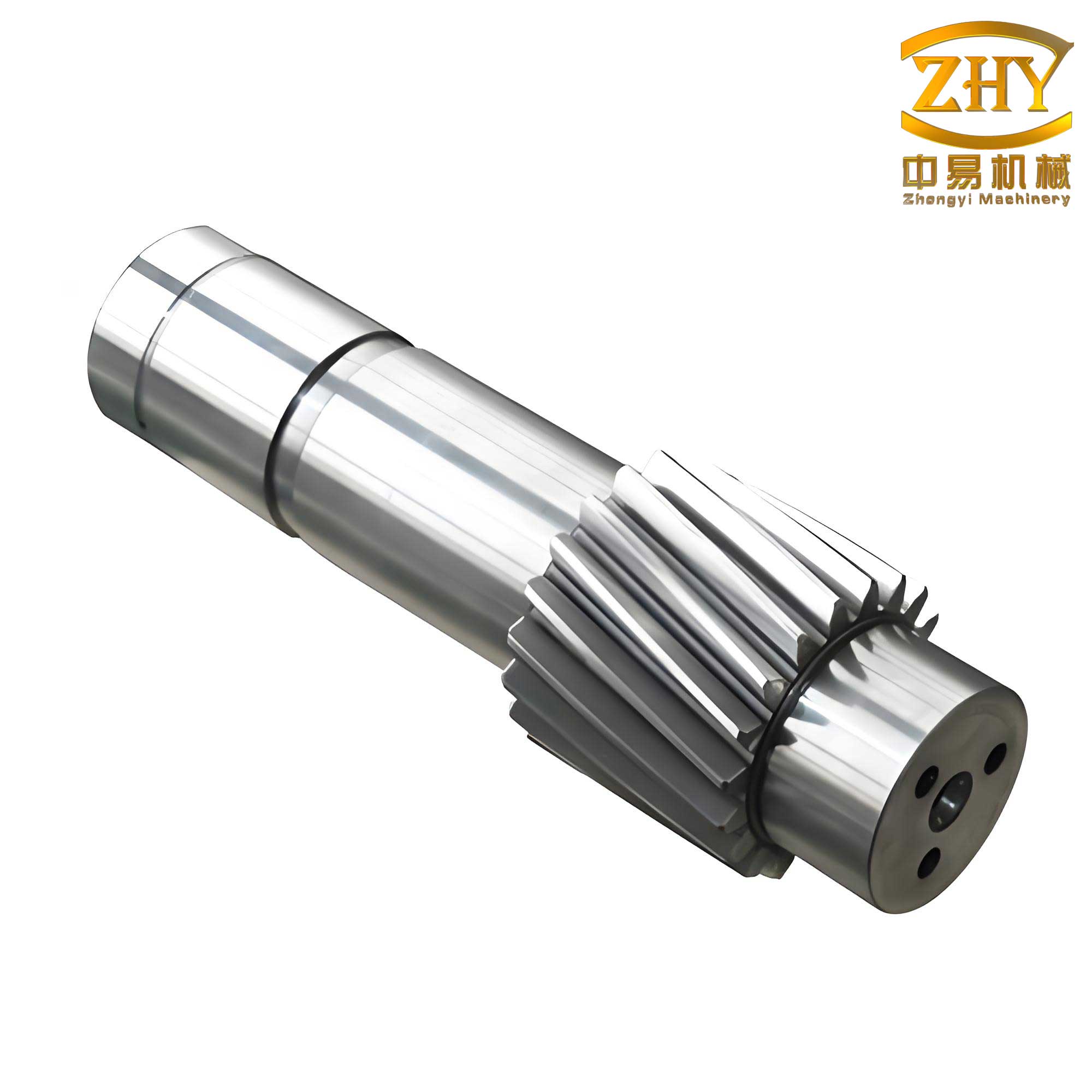
In my extensive experience maintaining heavy mineral processing equipment, few challenges are as urgent and technically demanding as the sudden failure of a critical drive component. I recall a particularly intense incident involving the gear shaft of a Φ5.5 × 8.5 m overflow ball mill at a copper slag concentrator. The sudden, violent failure of teeth on the pinion gear shaft brought the entire operation to an immediate halt. The characteristic loud report and subsequent vibration alarm signaled a catastrophic failure, later confirmed as the fracture and崩齿 (tooth breakage) of two adjacent teeth on the high-speed pinion gear shaft. This gear shaft, a vital link transferring torque from the motor to the massive mill shell, had suffered a classic fatigue failure under anomalous conditions. The immediate challenge was clear: without a replacement gear shaft—a procurement lead time of at least three months—production would be crippled. This narrative details the first-person investigative and remediation process, focusing on the root cause analysis of the gear shaft failure and the successful execution of an on-site repair using advanced pulsed-arc冷补焊 (cold repair welding) technology.
The failed component was the pinion gear shaft, manufactured from S17Cr2Ni2Mo (equivalent to 17CrNiMo4) carburizing steel. This material is chosen for gear shafts承受 heavy cyclic loads due to its ability to develop a hard, wear-resistant surface while maintaining a tough, ductile core. The specifications were rigorous: a surface hardness of 57–62 HRC from carburizing and quenching, a case depth of 3–5 mm, a gear module of 28, 21 teeth, a face width of 910 mm, and a precision grade of 6. Upon shutdown and inspection, the damage was localized but severe. Two teeth, labeled here as Tooth A and Tooth B for reference, exhibited complete fracture, with fragments roughly 150 mm in length, 80 mm in width, and varying in depth from 5 to 35 mm. The fracture surfaces were located near one end of the gear face width. A critical observation was the uneven wear pattern; the backlash on the left side of the gear mesh was 2–3 mm smaller than on the right side, indicating a pronounced unilateral bias in the load distribution along the gear shaft axis. This misalignment was the first clue pointing away from a simple overload and towards a systemic issue.
The forensic analysis of the fracture surfaces was revealing. Macroscopically, the fractures showed distinct zones: a smooth, fine-grained area indicative of the crack initiation site (fatigue origin), a progression zone with characteristic beach marks from cyclic crack growth, and a final, rougher instantaneous fracture zone. The origin zones on both teeth were located at the left-side end face of the gear teeth, precisely where the measured偏载 (biased load) was most severe. Crucially, there were no signs of impact from foreign objects, such as indentations or embedded material, on the mating surfaces adjacent to the fractures. This ruled out an instantaneous overload from a tramp metal event as the primary cause. The failure mechanism was clearly fatigue, initiated by a stress concentration. Further investigation pinpointed the root cause: the axial locating block for the gear shaft’s bearing had detached. This allowed the entire gear shaft assembly to shift axially under load, creating the observed unilateral contact and massive偏载. The local stress at the end of the contact line on the gear teeth would have soared far above the design limits.
To quantify the stress condition, we can consider the fundamental bending stress at the tooth root, the point of highest stress for a gear tooth. The Lewis formula provides a simplified model:
$$ \sigma_b = \frac{F_t}{b m_n Y} $$
Where \( \sigma_b \) is the bending stress, \( F_t \) is the tangential load at the pitch circle, \( b \) is the face width, \( m_n \) is the normal module, and \( Y \) is the Lewis form factor. Under偏载, the effective face width \( b_{eff} \) is drastically reduced. If the load is concentrated over only, say, 30% of the face width due to misalignment, the stress effectively triples: \( \sigma_{b,偏载} \approx \frac{F_t}{0.3b m_n Y} \). This elevated stress, coupled with the stress concentration factor \( K_t \) at the tooth fillet (which can be 1.5 to 2.5 for typical gear profiles), drives the maximum local stress well into the range where fatigue cracks can nucleate from microscopic imperfections. The fatigue crack growth rate can be described by the Paris-Erdoğan law for stable crack propagation:
$$ \frac{da}{dN} = C (\Delta K)^m $$
Here, \( da/dN \) is the crack growth per cycle, \( \Delta K \) is the stress intensity factor range, and \( C \) and \( m \) are material constants. The偏载 condition caused a high \( \Delta K \), accelerating crack growth from the initiation site at the left end face until the remaining ligament could no longer support the load, leading to final, catastrophic fracture of the gear shaft teeth. This analysis underscored that the integrity of the entire bearing and mounting system is paramount for the health of the gear shaft.
Before any repair could be contemplated, a thorough理化检验 (physical and chemical testing) of the failed gear shaft material was essential to inform the welding procedure. Samples were taken from the fracture region for spectroscopic analysis and hardness traversals. The results confirmed the gear shaft material was within specification.
| Element | C | Si | Mn | S | P | Cr | Mo | Ni |
|---|---|---|---|---|---|---|---|---|
| Standard Range (S17Cr2Ni2Mo) | 0.14–0.19 | 0.15–0.40 | 0.40–0.60 | ≤0.035 | ≤0.035 | 1.5–1.8 | 0.25–0.35 | 1.40–1.70 |
| Measured Value | 0.16 | 0.27 | 0.50 | 0.028 | 0.030 | 1.65 | 0.28 | 1.50 |
| Measurement Zone | Hardness Value | Notes |
|---|---|---|
| Tooth Surface | 60 HRC | Equivalent to ~697 HV |
| Case Depth | 3.5 mm | Depth at which hardness drops to ~550 HV |
| Core (below case) | 36.5 HRC | Equivalent to ~341 HV |
The data confirmed we were dealing with a correctly manufactured, high-hardness surface gear shaft. Any repair would need to restore geometry, bond metallurgically to this substrate, and approximate the original surface hardness to prevent rapid wear. Traditional arc welding methods were deemed too risky due to the high heat input, which could cause distortion, residual stresses, cracking in the heat-affected zone (HAZ), and severe softening of the hard carburized case. The transformation of martensite in the HAZ back to softer phases like ferrite and pearlite is a function of the thermal cycle’s peak temperature and cooling rate. The severity of softening can be conceptually related to the thermal experience, often encapsulated in parameters like the Rosenthal heat input for a moving source, but controlling this on a complex gear shaft geometry is exceedingly difficult.
After evaluating alternatives, we selected the电脉冲冷补焊工艺 (Electro-pulsing Cold Repair Welding). This process is fundamentally different from conventional welding. It uses short-duration, high-current electrical pulses to create a micro-weld pool that solidifies almost instantaneously. The total energy delivered per pulse is extremely low, minimizing heat diffusion into the parent gear shaft material. The principle can be likened to capacitor discharge welding. The energy per pulse \( E_p \) is given by:
$$ E_p = \frac{1}{2} C V^2 $$
where \( C \) is the capacitance and \( V \) is the charging voltage. With pulse durations \( t_p \) on the order of milliseconds, the average power \( P_{avg} \) during a pulse is high, but the total heat input \( Q_{total} \) into the workpiece over the entire repair session remains very small because the duty cycle is low:
$$ Q_{total} = \sum_{i=1}^{n} E_{p,i} \cdot \eta \approx n \cdot \frac{1}{2} C V^2 \cdot \eta $$
Here, \( n \) is the number of pulses and \( \eta \) is the thermal efficiency. This results in a negligible rise in bulk temperature of the gear shaft, keeping the HAZ confined to a few tens of micrometers. This was critical for preserving the core properties and avoiding distortion of the precision gear shaft.
The on-site repair protocol was meticulous. First, the fracture areas on the gear shaft were mechanically prepared. Using angle grinders and precision tools, all damaged material was removed until sound metal was reached. The cavities were shaped with smooth contours and generous radii to avoid new stress concentrators. Each prepared site was then subjected to liquid penetrant testing (PT) to ensure all micro-cracks from the fatigue event had been eliminated. The PT process, relying on capillary action, was repeated after each grinding stage until a clean surface was confirmed. The gear shaft was then positioned so that the repair areas were horizontal, facilitating deposition.
The welding sequence was designed to manage dilution, residual stress, and final hardness. We employed a multi-layer, multi-material strategy. The first layer, directly onto the gear shaft substrate, used a nickel-chromium alloy wire. This layer provides excellent crack resistance and bonds well to both the steel substrate and subsequent layers. Intermediate layers were deposited using AISI 304 stainless steel wire and a medium-carbon steel wire, applied in alternating sequence. This combination helps in stress redistribution and achieves a gradual transition in mechanical properties. The final capping layer used a high-hardness alloy wire capable of being work-hardened to接近 (approach) the original surface hardness. The welding parameters for the pulsed-arc machine were tightly controlled: pulse current between 90–120 A, rapid traversal speed, and no weaving motion to concentrate the heat. An essential step was peening each layer (except the first and last) with a pneumatic needle scaler or hammer. Peening induces beneficial compressive surface stresses, which counteract tensile welding stresses and improve fatigue resistance of the repaired gear shaft zone.
The integrity of the weld deposit on the gear shaft was paramount. We conducted a battery of adhesion and quality tests, adapting standard methods for the field environment:
| Test Method | Procedure | Acceptance Criterion |
|---|---|---|
| File Test | Filing the weld interface at a 45° angle from base metal towards weld. | No peeling or delamination of the weld layer. |
| Chisel/Scratch Grid Test | Creating a cross-hatched grid of cuts through the weld layer to the substrate. | No lifting or flaking of the squares within the grid. |
| Local Grind Test | Grinding away part of the weld layer to create a sharp step exposing the substrate. | No spalling or detachment at the step boundary. |
| Hammer Impact Test | Striking the weld deposit sharply with a ball-peen hammer. | No cracking, lifting, or crater formation around the impact. |
| Bend Test (on coupon) | Bending a welded sample plate 180° around a mandrel. | No separation of the weld layer from the base plate. |
All tests performed on sample coupons and on non-critical areas of the actual gear shaft repair passed satisfactorily, confirming a metallurgical bond stronger than the base material’s shear strength in many cases.
The final and most critical phase was the restoration of the precise gear tooth geometry on the gear shaft. Using the adjacent undamaged teeth as a master reference, we meticulously built up the weld metal to slightly above the final profile. The rough shape was achieved with grinding wheels. Finishing was done with finer abrasive stones, polishing tools, and constant checking against a master gear tooth template and precision measuring instruments like micrometers and dial indicators. The goal was to match the original involute profile, lead (helix angle), and pitch within the tight tolerances required for a Grade 6 gear. The final surface finish was critical to ensure proper oil film formation and avoid scuffing. After machining, the repaired teeth were again inspected with penetrant testing to confirm the absence of grinding cracks. The final hardness of the welded surfaces was measured using a portable Rockwell hardness tester and found to be in the range of 58-60 HRC, nearly identical to the original gear shaft surface.
The repaired gear shaft was reinstalled in the mill drive train. The root cause of the failure—the bearing定位 block—was redesigned and securely fastened. The gear alignment was carefully checked and adjusted to ensure even load distribution across the full face width of the gear shaft. The mill was started under no-load conditions for observation, followed by gradual ramping up to full operational load over 24 hours. Vibrational analysis was conducted throughout, showing levels well within acceptable limits and identical to pre-failure baseline readings. The gear mesh noise was smooth and uniform. The success of the repair was not short-lived; the ball mill, with its resurrected gear shaft, has now been in continuous operation for over six months without any issues related to the repair. Periodic inspections show no signs of wear, cracking, or deformation in the repaired sections of the gear shaft.
This project served as a powerful testament to the viability of advanced, low-heat-input welding techniques for the salvage of high-value, seemingly irreparable components like a large gear shaft. The key was a systematic approach: a rigorous root-cause analysis to prevent recurrence, comprehensive material characterization of the gear shaft, selection of a thermally gentle repair process, a scientifically designed welding procedure, and relentless quality control. The电脉冲冷补焊 process proved its worth by depositing material with minimal thermal distortion and excellent adhesion, enabling precise geometric restoration. For industries reliant on heavy machinery, where downtime costs are astronomical and replacement lead times are long, mastering such gear shaft repair methodologies is not just a cost-saving measure—it is a critical operational competency. The lessons learned, particularly around the sensitivity of gear shafts to偏载 from mounting failures, have been incorporated into preventive maintenance schedules across the facility, safeguarding other critical gear shafts from similar fates.