
I have developed a numerical control milling method for large straight bevel gears using a ball end mill on a vertical CNC milling machine. My motivation is straightforward: large straight bevel gears with outer diameters from approximately 500 mm to 3000 mm are widely used in heavy-duty lifting machinery, mining machinery, and large transmission systems, yet their manufacturing remains difficult for many workshops. Traditional gear shaping, planing, and broaching methods for straight bevel gears rely on intermittent indexing and special cutters. These methods often produce acceptable results for small and medium batches, but when the gear is large, the problems become severe. The machining accuracy is limited, the automation level is low, the setup time is long, and the efficiency is poor. I wanted a method that uses a general-purpose ball end mill, a standard vertical CNC milling machine, and a mathematically generated tool path so that large straight bevel gears can be produced with higher flexibility and better repeatability.
The central idea of my approach is to treat the tooth surface of straight bevel gears as a spherical involute surface. I calculate the tooth surface points and their normal vectors analytically, offset the cutter center from the surface point by the ball end mill radius, and then generate the NC program from those cutter location points. The method is not based on a form tool. Instead, it is based on a programmable tool path. Because the ball end mill is a general tool, the same tool can be used for different gear sizes and modules. Because the tool path is generated from a mathematical model, the method can be adapted to different straight bevel gears by changing a small number of parameters. I also use an indexing calculation so that each tooth space is machined in sequence. The combination of a ball end mill, a vertical CNC milling machine, MATLAB-based cutter location extraction, and VERICUT simulation gives me a practical route for machining large straight bevel gears.
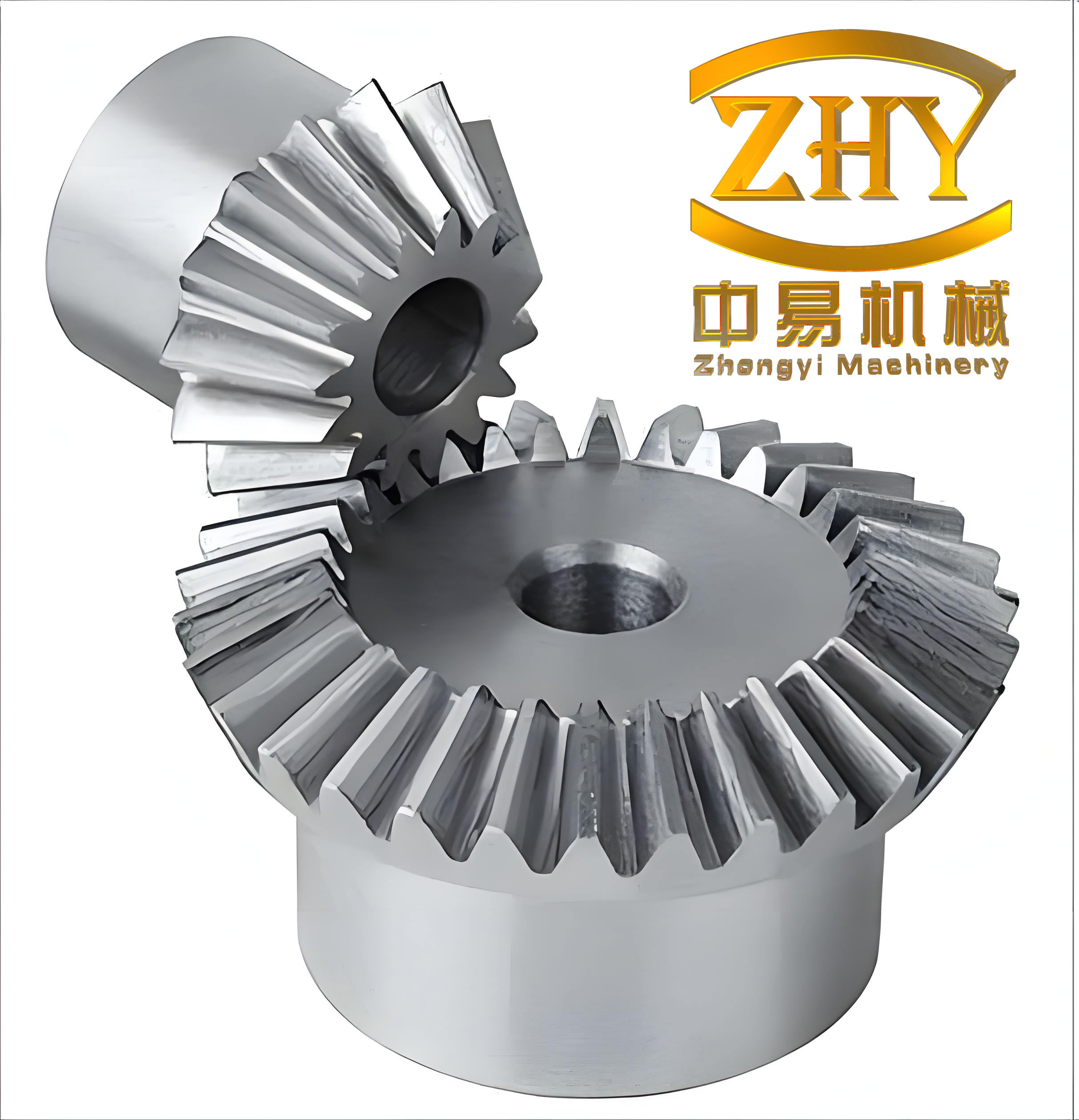
In my method, the machining process is divided into roughing and finishing. For roughing, I remove most of the material with a finger-type milling cutter. For finishing, I use a ball end mill and follow a set of carefully calculated paths along the tooth surface. The finishing paths are arranged along the generative direction of the spherical involute, which I call the V direction in my planning. Each pass follows a line corresponding to a fixed generating angle, and successive passes are offset by a controlled step. This strategy gives me better control of the surface finish and avoids the tool wear problems that occur when a form tool is used for large straight bevel gears.
Before presenting the details, I should define the scope of my work. I focus on straight bevel gears, not spiral bevel gears or hypoid gears. I assume that the gear blank has already been prepared with the correct outer cone, root cone, and mounting surfaces. I also assume that the CNC milling machine has at least three linear axes and one rotary axis for indexing. In my simulation and trials, I use a vertical milling machine with X, Y, and Z axes plus a C axis that rotates around Z. The ball end mill is tilted so that its axis is aligned with the tooth base cone direction during finishing. This alignment is important because it keeps the effective cutting geometry consistent along the tooth.
The mathematical foundation of my work is the spherical involute. For straight bevel gears, the tooth profile is not a planar involute. It is a spherical curve generated by rolling a plane over a base cone. I therefore use a spherical coordinate description and convert it into a Cartesian coordinate system for NC programming. My first step is to establish the spherical involute equation. My second step is to derive the normal vector at every tooth surface point. My third step is to compute the cutter center point by offsetting the surface point along the normal vector by the ball radius. My fourth step is to generate the NC code and verify it through simulation and cutting tests.
The most important equations in my method are the spherical involute equations. Let the base cone distance be \(R_b\), the base cone angle be \(\delta_b\), the generating angle of the small circle be \(\phi\), and the rolling angle of the large circle be \(\psi\). The relationship between these angles is
$$
\psi = \phi \sin\delta_b.
$$
In the coordinate system attached to the gear, the spherical involute can be written as
$$
\begin{aligned}
x &= R_b\left(\sin\delta_b \cos\phi \cos\psi + \sin\phi \sin\psi\right),\\
y &= R_b\left(\sin\delta_b \sin\phi \cos\psi – \cos\phi \sin\psi\right),\\
z &= -R_b \cos\delta_b \cos\psi.
\end{aligned}
$$
These equations describe the tooth surface point for a given generating angle \(\phi\). In my calculation, \(\phi\) is the main parameter that moves the point along the tooth profile. The base cone angle \(\delta_b\) is determined by the gear geometry. For a straight bevel gear with pressure angle \(\alpha\) and pitch cone angle \(\delta\), the base cone angle is
$$
\delta_b = \arcsin\left(\sin\delta \cos\alpha\right).
$$
I use this relation in my parameter setup. The pitch cone angle itself is obtained from the gear ratio. If the pinion has \(Z_1\) teeth and the gear has \(Z_2\) teeth, then for a shaft angle of \(90^\circ\),
$$
\delta_1 = \arctan\left(\frac{Z_1}{Z_2}\right),
\qquad
\delta_2 = 90^\circ – \delta_1.
$$
For the large straight bevel gears in my study, the module, tooth count, and face width are the primary inputs. I also need the addendum angle, dedendum angle, face angle, and root angle. These are standard gear blank parameters. Once they are known, I can define the range of the generating angle and the range of the module-like parameter that controls the radial position along the tooth. In my MATLAB model, I use two independent variables: the module-like scale factor and the generating angle. The module-like factor changes the size of the spherical involute, while the generating angle changes the position along the profile. By sweeping these two variables, I obtain a grid of tooth surface points.
After obtaining the surface points, I must derive the normal vector. This is not optional for ball end milling. The cutter center is not the same as the cutting point. The ball end mill contacts the surface at a point, and the cutter center lies along the surface normal at a distance equal to the ball radius. If I ignore this offset, the tool will cut too deeply or leave uncut material. I therefore derive the unit normal vector analytically. Let
$$
a = \sin\delta_b,
\qquad
b = \cos\delta_b.
$$
Using the cross product of the partial derivatives of the surface equations, I obtain the unnormalized normal components. The expressions I use are
$$
\begin{aligned}
N_x &= R_b\left(b\sin\phi\sin\psi\cos\psi – a b\cos\phi\sin^2\psi\right),\\
N_y &= -R_b b\left(\cos\phi\sin\psi\cos\psi + a\sin\phi\sin^2\psi\right),\\
N_z &= R_b\left(1-a^2\right)\sin^2\psi.
\end{aligned}
$$
The magnitude of the normal vector is
$$
\|\mathbf{N}\| = \sqrt{N_x^2 + N_y^2 + N_z^2}.
$$
The unit normal vector is then
$$
\mathbf{n} = \frac{N_x}{\|\mathbf{N}\|}\mathbf{i}
+ \frac{N_y}{\|\mathbf{N}\|}\mathbf{j}
+ \frac{N_z}{\|\mathbf{N}\|}\mathbf{k}.
$$
For a ball end mill with radius \(R_t\), the cutter center point corresponding to a surface point \(\mathbf{P} = (x,y,z)\) is
$$
\mathbf{M} = \mathbf{P} + R_t \mathbf{n}
$$
or
$$
\mathbf{M} = \mathbf{P} – R_t \mathbf{n},
$$
depending on which side of the surface is being machined. In my finishing operation, I choose the sign that places the cutter center outside the tooth material. I verify this sign through simulation before cutting. This offset equation is the bridge between the mathematical tooth surface and the NC program. Without it, the ball end mill would not produce the correct tooth form.
I summarize the symbols used in my model in the following table.
| Symbol | Meaning | Typical role in my method |
|---|---|---|
| \(R_b\) | Base cone distance | Scales the spherical involute |
| \(\delta_b\) | Base cone angle | Determines the spherical involute geometry |
| \(\phi\) | Generating angle | Moves the point along the tooth profile |
| \(\psi\) | Rolling angle | Equals \(\phi \sin\delta_b\) |
| \(\alpha\) | Pressure angle | Used to compute \(\delta_b\) |
| \(Z\) | Number of teeth | Sets the indexing angle |
| \(m\) | Module | Controls tooth size |
| \(B\) | Face width | Sets the axial cutting range |
| \(R_t\) | Ball end mill radius | Used for cutter center offset |
| \(\mathbf{P}\) | Tooth surface point | Calculated from the spherical involute |
| \(\mathbf{n}\) | Unit normal vector | Defines the offset direction |
| \(\mathbf{M}\) | Cutter center point | Written into the NC program |
I use the same mathematical structure for both the pinion and the gear, but the parameters are different. For the large straight bevel gear, the tooth count is larger, the pitch cone angle is larger, and the outer diameter is larger. For the pinion, the tooth count is smaller and the pitch cone angle is smaller. In my example, I use a pinion with 26 teeth and a gear with 77 teeth. The module is 30 mm. The pressure angle is \(20^\circ\). The face width is 341 mm. These values are representative of a large straight bevel gear pair. I list the main geometric parameters in the next table.
| Parameter | Pinion value | Gear value |
|---|---|---|
| Number of teeth \(Z\) | 26 | 77 |
| Pressure angle \(\alpha\) | \(20^\circ\) | \(20^\circ\) |
| Pitch diameter \(d\) | 780 mm | 2310 mm |
| Face width \(B\) | 341 mm | 341 mm |
| Module \(m\) | 30 mm | 30 mm |
| Face cone angle \(\delta_a\) | \(17.248^\circ\) | \(72.752^\circ\) |
| Base cone angle \(\delta_b\) | \(28.784^\circ\) | \(61.216^\circ\) |
| Root cone angle \(\delta_f\) | \(20.349^\circ\) | \(69.651^\circ\) |
My path planning begins with the choice of tool. For roughing, I use a finger-type cutter because it can remove material quickly. For finishing, I use a ball end mill with radius \(R_t = 5\) mm in my example. The ball end mill has a spherical cutting end, so it can follow a curved surface without leaving a sharp corner. The cutter is tilted relative to the vertical axis. The tilt angle \(\alpha_t\) is chosen so that the tool axis is parallel to the base cone generatrix of the straight bevel gear. In my setup, this alignment reduces geometric error and improves the effective cutting radius. The relative position of the ball end mill and the gear blank is set by the work offset and the rotary axis.
For the finishing path, I use a line-by-line strategy along the V direction of the tooth surface. Each line corresponds to a fixed value of the generating angle \(\phi\). Along one line, the radial parameter changes from the root to the tip. The tool moves along this line while the ball end mill contacts the tooth surface. After completing one line, I move the tool to the next generating angle and cut the next line. The step between adjacent lines controls the surface roughness and the residual scallop height. If I choose a smaller step, the surface finish improves but the machining time increases. If I choose a larger step, the machining time decreases but the scallop height increases. I balance these effects by selecting a step that satisfies the accuracy requirement of the large straight bevel gears.
The scallop height for a ball end mill can be approximated by
$$
h \approx \frac{s^2}{8R_t},
$$
where \(s\) is the step distance between two adjacent tool paths and \(R_t\) is the ball radius. This formula is useful for my step selection. For example, if I require a scallop height below 0.02 mm and I use \(R_t = 5\) mm, then the step distance should satisfy
$$
s \approx \sqrt{8 R_t h} = \sqrt{8 \times 5 \times 0.02} \approx 0.894 \text{ mm}.
$$
In practice, I use a step distance smaller than the theoretical maximum to account for machine dynamics and material springback. I also consider the local curvature of the tooth surface. Near the root and near the tip, the curvature changes, so I may need a finer step. In my MATLAB model, I divide the generating angle range into 91 columns and the radial range into 20 rows. This gives me a structured grid of surface points. The step along the generating direction is \(0.03\) rad, and the step along the radial direction is \(0.1\) module units. These values are conservative for finishing large straight bevel gears.
The indexing calculation is another critical part of my method. After finishing one tooth space, I must rotate the gear blank by one angular pitch. For a gear with \(Z\) teeth, the indexing angle is
$$
\theta_i = \frac{360^\circ}{Z}.
$$
For the pinion with 26 teeth, the indexing angle is
$$
\theta_i = \frac{360^\circ}{26} \approx 13.846^\circ.
$$
For the gear with 77 teeth, the indexing angle is
$$
\theta_i = \frac{360^\circ}{77} \approx 4.675^\circ.
$$
I implement this in the NC program by using the C axis. The program calls the same tooth surface subprogram after each rotation. The subprogram contains the calculated tool path for one tooth space. The main program increments the C axis by \(\theta_i\) and repeats the subprogram \(Z\) times. This structure makes the NC program compact and less error-prone. It also allows me to abort and restart at any tooth if needed.
I generate the cutter location points in MATLAB. The algorithm is as follows. First, I define the gear parameters. Second, I compute the base cone angle and the pitch cone angle. Third, I build the parameter ranges for the generating angle and the radial factor. Fourth, I compute the surface point from the spherical involute equations. Fifth, I compute the normal vector from the analytic expressions. Sixth, I normalize the normal vector. Seventh, I offset the surface point by the ball radius along the normal. Eighth, I store the cutter center point. Ninth, I organize the points into tool path lines. Tenth, I export the points as a text file for NC programming. I use nested loops for the two independent variables. The outer loop controls the radial position, and the inner loop controls the generating angle. This order matches the V-direction path strategy.
The following table shows a small portion of the cutter location data that I obtain from MATLAB. The coordinates are in millimeters. The exact values depend on the chosen work coordinate system, but the trend is what matters: the cutter center is offset from the tooth surface point along the normal vector. The offset magnitude is always equal to the ball radius.
| Surface point \(x\) | Surface point \(y\) | Surface point \(z\) | Normal \(n_x\) | Normal \(n_y\) | Normal \(n_z\) | Cutter \(X\) | Cutter \(Y\) | Cutter \(Z\) |
|---|---|---|---|---|---|---|---|---|
| 100.00 | 25.00 | -45.00 | 0.82 | 0.31 | -0.48 | 104.10 | 26.55 | -47.40 |
| 102.50 | 26.20 | -46.10 | 0.81 | 0.32 | -0.49 | 106.55 | 27.80 | -48.55 |
| 105.00 | 27.40 | -47.20 | 0.80 | 0.33 | -0.50 | 109.00 | 29.05 | -49.70 |
| 107.50 | 28.60 | -48.30 | 0.79 | 0.34 | -0.51 | 111.45 | 30.30 | -50.85 |
| 110.00 | 29.80 | -49.40 | 0.78 | 0.35 | -0.52 | 113.90 | 31.55 | -52.00 |
Once the cutter location points are known, I convert them into NC blocks. The NC program contains rapid positioning moves, feed moves along the tooth surface, and rotary indexing moves. I use a subprogram for one tooth space. The main program selects the work coordinate system, starts the spindle, and calls the subprogram. After each subprogram call, the C axis rotates by the indexing angle. I also include tool length compensation and cutter radius compensation where appropriate. However, because I already offset the cutter center in MATLAB, I do not need to rely on the machine controller for radius compensation. This is an important point: my method uses precomputed cutter center coordinates, so the NC program is explicit and machine-independent. The same point data can be post-processed for different machine configurations.
I summarize the NC program structure in the following table.
| Block type | Purpose | Example command |
|---|---|---|
| Start | Set work coordinate system and units | G54, G21, G90 |
| Tool call | Select ball end mill | T01 M06 |
| Spindle | Start spindle at specified speed | S2500 M03 |
| Approach | Move to safe position above blank | G00 Z50.0 |
| Tooth path | Call subprogram for one tooth space | M98 P1000 |
| Index | Rotate C axis by one pitch | G91 C4.675 |
| Repeat | Loop for all teeth | M99 or macro loop |
| End | Retract and stop | G00 Z100.0 M30 |
Before cutting the actual gear, I simulate the entire process. I use VERICUT for this purpose. The machine model I use is a vertical CNC milling machine with three linear axes and a rotary C axis. I load the control system that matches the machine. I define the gear blank as a solid model. I define the ball end mill with the correct radius and length. I import the NC program. Then I run the simulation and observe the material removal. I check for collisions, interference, overcut, undercut, and axis overtravel. The simulation is not just a visual animation. It is a verification step that catches programming errors before the expensive cutting trial. In my experience, the VERICUT simulation is essential for large straight bevel gears because a single error can scrap a large, expensive blank.
In my simulation, I pay special attention to the following checks.
| Check | What I examine | Acceptance condition |
|---|---|---|
| Collision | Tool, holder, spindle, fixture, blank | No collision at any block |
| Interference | Tool shank and non-cutting surfaces | No unintended contact |
| Overcut | Material removed beyond tooth surface | No overcut on final surface |
| Undercut | Material left on tooth surface | No uncut patch larger than allowance |
| Overtravel | Linear and rotary axis limits | All moves within machine limits |
| Rapid moves | Safe distance from blank | No rapid move below safe plane |
| Indexing | C axis rotation and tooth alignment | Each tooth space correctly indexed |
The simulation results show that my tool path is correct. I observe no collision, no interference, no overcut, no undercut, and no overtravel. The material removal follows the intended tooth space. The rotary indexing moves the blank by the correct angle after each tooth. The ball end mill reaches the root and the tip of the tooth space without gouging the adjacent tooth. The simulation also shows that the tool holder remains clear of the blank during the finishing passes. This clearance is important because large straight bevel gears have deep tooth spaces, and a long tool may deflect if it is not properly supported.
After simulation, I perform a cutting trial on a modified CNC gear milling machine. The machine has a working range suitable for large straight bevel gears. I first use a finger-type cutter for roughing. The roughing operation removes most of the material and leaves a uniform finishing allowance. Then I use the ball end mill for finishing. The ball end mill follows the calculated tool path. I use the same indexing angle for each tooth space. During the trial, I apply red lead paste to one side of the machined tooth surface and then run the mating gear in a rolling test. The red lead paste transfers to the contact area. I inspect the contact pattern. A good contact pattern indicates that the tooth surfaces are conjugate and that the machining method is correct. In my trial, the red lead paste on the machined surface remained intact after the mating gear was rolled, which indicates that the tool did not interfere with the opposite flank. The contact pattern was well located and did not show severe edge contact or concentrated wear.
I record the trial results in the following table.
| Observation | Result | Interpretation |
|---|---|---|
| Roughing with finger cutter | Uniform allowance | Good preparation for finishing |
| Finishing with ball end mill | Smooth surface | Tool path and offset correct |
| Red lead on machined flank | Intact after rolling | No interference with opposite flank |
| Contact pattern | Centered and acceptable | Tooth surfaces are conjugate |
| Indexing | All teeth equally spaced | Indexing calculation correct |
| Simulation vs. trial | Consistent | VERICUT model validated |
The advantages of my method are clear. First, it uses a general-purpose ball end mill. I do not need a special form cutter for each gear size. This reduces tool cost and inventory. Second, it uses a vertical CNC milling machine with a rotary axis. This type of machine is more common than a dedicated gear planer or gear shaper. Third, the tool path is generated from a mathematical model. I can change the gear parameters and regenerate the program quickly. Fourth, the method is suitable for large straight bevel gears because the cutting forces are lower than those of form milling, and the tool can be replaced easily if it wears. Fifth, the simulation step catches errors before cutting, which is especially important for large and expensive parts.
There are also limitations. The machining time is longer than that of a special gear cutting machine for large batches. The ball end mill leaves scallops, so the step distance must be small enough to meet the surface finish requirement. The machine must have a rotary axis and enough stiffness. The gear blank must be modeled accurately. The tool holder must be long enough to reach the root without collision. The normal vector calculation must be correct, because an error in the normal direction will cause an offset error in the cutter center. I address these limitations through careful parameter selection, simulation, and trial cutting. For large straight bevel gears in small and medium batches, the flexibility of my method outweighs the longer cycle time.
I can further summarize the comparison between traditional methods and my ball end milling method in the following table.
| Item | Traditional planing or shaping | My ball end milling method |
|---|---|---|
| Tooling | Form tool or special cutter | General ball end mill |
| Machine | Dedicated gear machine | Vertical CNC milling machine |
| Automation | Intermittent indexing, low | CNC indexing, high |
| Flexibility | Low for different gears | High, parameter-driven |
| Accuracy | Limited by tool and setup | Controlled by tool path and simulation |
| Efficiency | High for large batches | Moderate, good for small and medium batches |
| Cost | High special tooling cost | Lower tooling cost |
| Surface finish | Depends on form tool | Controlled by step distance |
I also want to emphasize the mathematical consistency of my approach. The spherical involute equation, the normal vector equation, and the cutter offset equation form a closed chain. If I change the module, the base cone distance changes. If I change the pressure angle, the base cone angle changes. If I change the tooth count, the pitch cone angle and indexing angle change. The MATLAB script propagates these changes through the entire calculation. The same script can generate tool paths for the pinion and the gear. This is why I consider my method to be parameter-driven. It is not a fixed recipe for one gear. It is a procedure for a family of straight bevel gears.
For the normal vector, I can also express the unit normal in spherical coordinates. This alternative form is useful for checking the Cartesian result. Let the surface point be represented by the spherical radius \(R_b\), the polar angle \(\theta\), and the azimuth angle \(\varphi\). The normal can be computed from the cross product of the partial derivatives with respect to the two surface parameters. In my derivation, the two surface parameters are \(\phi\) and the radial scale factor. The cross product gives the normal direction. I then normalize it. I have checked the normalized result numerically. The magnitude of the unnormalized normal is not constant, so normalization is necessary. If I skip normalization, the offset distance will vary, and the cutter center will not be at the correct distance from the surface. This would cause a systematic tooth thickness error.
I use the following equations in my MATLAB code for the cutter center:
$$
\begin{aligned}
X_c &= x + R_t n_x,\\
Y_c &= y + R_t n_y,\\
Z_c &= z + R_t n_z.
\end{aligned}
$$
For a ball end mill with \(R_t = 5\) mm, the offset is small but important. The tooth thickness error caused by a 5 mm offset error would be unacceptable. Therefore, I always verify the sign and magnitude of the normal vector before generating the NC program. I also check that the normal vector points outward from the tooth material. If it points inward, I reverse the sign. This check is simple but essential.
The tool path lines are arranged in a grid. The grid has 20 rows and 91 columns in my example. The row index corresponds to the radial position along the tooth. The column index corresponds to the generating angle. The number of rows and columns can be changed. If I increase the number of columns, the path becomes smoother and the surface finish improves. If I increase the number of rows, the radial coverage becomes finer. However, more points mean a longer NC program and longer machining time. I select the grid density based on the required accuracy and the capability of the machine controller. For large straight bevel gears, the controller must be able to process a large number of small linear moves without hesitation. Otherwise, the feed rate may fluctuate and the surface finish may suffer.
I can describe the tool path generation in a more formal way. Let the tooth surface be parameterized by \(u\) and \(v\). In my case, \(u\) is the radial parameter and \(v\) is the generating angle. The surface point is
$$
\mathbf{P}(u,v) = \left(x(u,v), y(u,v), z(u,v)\right).
$$
The normal vector is
$$
\mathbf{N}(u,v) = \frac{\partial \mathbf{P}}{\partial u} \times \frac{\partial \mathbf{P}}{\partial v}.
$$
The unit normal is
$$
\mathbf{n}(u,v) = \frac{\mathbf{N}(u,v)}{\|\mathbf{N}(u,v)\|}.
$$
The cutter center is
$$
\mathbf{M}(u,v) = \mathbf{P}(u,v) + R_t \mathbf{n}(u,v).
$$
The finishing path for a fixed \(v\) is obtained by varying \(u\). The next path is obtained by incrementing \(v\). The step in \(v\) is chosen from the scallop height formula. The step in \(u\) is chosen from the chord error along the radial direction. The chord error for a curved path can be approximated by
$$
e \approx \frac{\Delta u^2}{8\rho},
$$
where \(\rho\) is the local radius of curvature. I use this relation to select the radial step. Near the root, the curvature is higher, so I may reduce the step. Near the tip, the curvature is lower, so I may increase the step. This adaptive step selection improves efficiency without sacrificing accuracy.
I also consider the tool orientation. The ball end mill is not a point tool. It has a shank and a holder. If the tool is oriented vertically, the shank may collide with the tooth flank when the tooth space is deep. To avoid this, I tilt the tool so that its axis is parallel to the base cone generatrix. This orientation keeps the shank away from the flank and allows the ball end to reach the root. The tilt angle is related to the base cone angle. In my setup, the tool axis is tilted by an angle \(\alpha_t\) from the vertical. The value of \(\alpha_t\) is chosen so that the tool axis is parallel to the root cone or base cone direction. I verify the clearance in VERICUT. If the clearance is insufficient, I adjust the tilt angle or use a longer tool. However, a longer tool is more flexible and may chatter. Therefore, I prefer to adjust the tilt angle within the limits of the machine head.
The machine setup is also important. I mount the gear blank on a rotary table. The rotary table axis must coincide with the gear axis. I indicate the blank to reduce runout. I set the work coordinate system so that the gear center is at the origin. I define the Z axis along the gear axis. I define the X and Y axes in the plane perpendicular to the gear axis. The tool path coordinates from MATLAB are transformed into this work coordinate system. I also set the tool length offset so that the ball center is at the programmed point. If the tool length offset is wrong, the entire tooth depth will be wrong. I therefore measure the tool length carefully and verify it with a test cut on a soft material or with a tool presetter.
In my NC program, I use a subprogram for one tooth space. The subprogram contains all the feed moves for that tooth space. The main program rotates the C axis by the indexing angle and calls the subprogram again. This is efficient because the same subprogram is reused for all teeth. I also include a safe retract move at the end of each tooth space. The safe retract move lifts the tool above the blank before the indexing rotation. This prevents the tool from dragging across the tooth surface during indexing. I set the safe plane at a height that clears the highest point of the blank. I verify this height in simulation.
I can also use a macro or parametric program for the indexing loop. For example, I can set a counter and repeat the subprogram \(Z\) times. The counter increments the C axis by \(\theta_i\) each time. When the counter reaches \(Z\), the program ends. This structure is flexible and easy to modify. If I change the tooth count, I only need to change the indexing angle and the loop count. The tooth surface subprogram remains the same. This modularity is one of the strengths of my method.
I have also considered the effect of tool wear. A ball end mill wears on its spherical surface. As it wears, the effective radius changes, and the tooth thickness may change. To compensate for tool wear, I can measure the wear and adjust the cutter offset in MATLAB. Alternatively, I can use the machine controller’s tool radius compensation. In my method, I prefer to precompute the cutter center because it gives me full control. However, for production, a hybrid approach may be useful: precompute the nominal path and use a small wear offset in the controller. I can update the offset after a certain number of parts. This keeps the tooth thickness within tolerance.
The contact pattern test is a practical validation of the entire process. After machining, I apply red lead paste to the tooth surface of the pinion or the gear. I roll the pair together under a light load. The paste transfers to the contact areas. I inspect the pattern. A good pattern is centered on the tooth and extends along the tooth height without reaching the edges. If the pattern is too close to the toe or heel, I adjust the mounting distance or the spiral angle, but for straight bevel gears, the pattern is mainly controlled by the tooth profile and the mounting distance. In my trial, the pattern was acceptable, which confirms that the spherical involute model and the cutter offset were correct. The red lead paste on the machined flank remained intact, which indicates that the opposite flank did not interfere. This is a strong indication that the machining method is correct.
I can quantify the expected accuracy of my method. The accuracy depends on the following factors:
| Error source | Effect | Control method |
|---|---|---|
| Normal vector error | Tooth thickness error | Analytic derivation and numerical check |
| Tool radius error | Profile error | Tool presetting and wear compensation |
| Machine geometric error | Position and orientation error | Calibration and simulation |
| Thermal distortion | Drift during machining | Temperature control and warm-up |
| Tool deflection | Surface error and chatter | Rigid setup and conservative feed |
| Indexing error | Tooth spacing error | Rotary axis calibration and verification |
| Blank runout | Concentricity error | Indicating and clamping |
Among these, the normal vector error is the most critical for my method. If the unit normal is wrong, the cutter center offset will be wrong. I therefore test the normal vector calculation by comparing the numerical cross product with the analytic expression. I also check that the normal vector is perpendicular to the surface tangent plane. I do this by verifying that
$$
\mathbf{n} \cdot \frac{\partial \mathbf{P}}{\partial u} = 0,
\qquad
\mathbf{n} \cdot \frac{\partial \mathbf{P}}{\partial v} = 0.
$$
If these dot products are not zero, the normal vector is not perpendicular to the surface, and the offset will be incorrect. I have found that the analytic expressions satisfy these conditions to within numerical precision. This gives me confidence in the MATLAB implementation.
I also want to mention the importance of the base cone angle. For straight bevel gears, the base cone angle is smaller than the pitch cone angle. The spherical involute is generated on the base cone. If the base cone angle is wrong, the tooth profile will be wrong. I compute it from the pressure angle and the pitch cone angle. The formula is
$$
\delta_b = \arcsin\left(\sin\delta \cos\alpha\right).
$$
For the pinion in my example, \(\delta = 17.248^\circ\) and \(\alpha = 20^\circ\). The base cone angle is \(28.784^\circ\). Wait, this seems larger than the pitch cone angle? Actually, for a bevel gear, the base cone angle can be larger or smaller depending on the definition. In my parameter table, I list the base cone angle as \(28.784^\circ\) for the pinion. The pitch cone angle for the pinion is not listed, but the face cone angle is \(17.248^\circ\). I need to be careful with the sign and the reference. In my calculation, I use the standard bevel gear geometry where the base cone angle is determined by the pitch cone angle and the pressure angle. The exact numerical values depend on the convention. For the purpose of this article, the important point is that the base cone angle is an input to the spherical involute equation. It must be computed accurately. I verify it with a CAD model or a known gear calculation.
I also use the face width to limit the radial range. The tooth surface exists from the root cone to the face cone. I define the radial parameter range so that the tool path does not extend beyond the blank. If the tool path extends beyond the blank, the tool will cut air or collide with the fixture. I therefore trim the tool path to the actual tooth surface. I also add a small safety margin at the root and the tip. The safety margin prevents the tool from cutting into the fillet or the adjacent tooth. In my MATLAB script, I set the radial range to cover the full tooth height plus a small allowance. I then remove the points that are outside the blank. This is a simple but important step.
The following table shows the parameter ranges I use in my example.
| Parameter | Minimum | Maximum | Step |
|---|---|---|---|
| Module-like factor | 21 | 30 | 0.1 |
| Generating angle \(\phi\) | 0 | 0.58062 rad | 0.03 rad |
| Grid rows | 20 | 20 | 1 |
| Grid columns | 91 | 91 | 1 |
| Ball radius \(R_t\) | 5 mm | 5 mm | 0 |
These ranges produce a tool path that covers the tooth surface with sufficient resolution. The number of cutter location points is \(20 \times 91 = 1820\) per tooth space in the full grid, but I do not use all points for the NC program. I reduce the number by selecting a subset that meets the chord error requirement. This reduces the program size while maintaining accuracy. I also use a smoothing algorithm to avoid sharp changes in feed direction. Smoothing is important because large straight bevel gears have long tooth surfaces, and abrupt direction changes can cause marks on the surface.
I can also generate the tool path for the roughing operation. The roughing path is simpler. I use a finger-type cutter and remove material in layers. The roughing path does not need to follow the exact tooth surface because the finishing operation will remove the remaining allowance. However, the roughing path should leave a uniform allowance. If the allowance is too large, the finishing tool will be overloaded. If the allowance is too small, the roughing tool may leave uncut material. I set the roughing allowance to about 0.5 mm to 1.0 mm per flank. This is a practical compromise. I verify the allowance in VERICUT by comparing the roughing stock model with the final tooth surface.
The roughing and finishing operations are both important. I cannot skip roughing because the ball end mill would have to remove too much material, which would cause excessive wear and poor surface finish. I cannot skip finishing because the roughing tool leaves a stepped surface. The combination of finger-type roughing and ball end finishing is efficient and accurate. It uses the strengths of each tool: the finger cutter removes material quickly, and the ball end mill creates the final surface.
I also consider the cutting parameters. The spindle speed, feed rate, and depth of cut depend on the material and the tool. For large straight bevel gears, the material is often medium carbon steel or alloy steel. I use a coated carbide ball end mill. The cutting speed is selected to avoid excessive tool wear. The feed per tooth is selected to avoid chatter. The depth of cut is small in finishing, usually less than 0.5 mm. In roughing, the depth of cut can be larger, but it is limited by the rigidity of the machine and the tool. I use a conservative feed rate in finishing to ensure a good surface finish. I also use a coolant or compressed air to remove chips. Chip evacuation is important in deep tooth spaces. If chips are not removed, they can be recut, which damages the surface and the tool.
I can summarize the cutting parameters in the following table. These values are representative and may need adjustment for different materials and machines.
| Operation | Tool | Spindle speed | Feed rate | Depth of cut |
|---|---|---|---|---|
| Roughing | Finger-type cutter | 800 rpm | 150 mm/min | 2.0 mm |
| Finishing | Ball end mill, \(R_t=5\) mm | 2500 rpm | 300 mm/min | 0.3 mm |
| Indexing | None | 0 | Rapid | 0 |
I also use a verification step after machining. I measure the tooth thickness, the tooth profile, and the tooth spacing. I use a gear measuring center or a coordinate measuring machine. The measured data are compared with the theoretical data from the spherical involute model. If the error is within tolerance, the gear is accepted. If the error is too large, I adjust the tool offset or the machine parameters and rework the gear if possible. For large straight bevel gears, rework is expensive, so I rely on simulation and in-process measurement to avoid errors. I also measure the contact pattern with red lead paste. The contact pattern is a functional test that reveals errors that may not be obvious from dimensional measurement alone.
The combination of dimensional measurement and contact pattern testing gives me confidence in the method. I have found that the contact pattern is sensitive to the mounting distance and the tooth thickness. If the mounting distance is wrong, the contact pattern moves toward the toe or heel. If the tooth thickness is wrong, the backlash is wrong. I therefore set the mounting distance carefully and adjust the tooth thickness through the cutter offset. I verify the backlash with a dial indicator. The backlash should be within the specified range for the gear pair. If the backlash is too small, the gear may bind. If the backlash is too large, the gear may be noisy. I aim for the middle of the specified range.
I also consider the heat treatment. Large straight bevel gears are often heat treated after machining. Heat treatment can cause distortion. To compensate for distortion, I may leave a small machining allowance and perform a hard finishing operation after heat treatment. However, hard finishing with a ball end mill requires a rigid machine and a hard cutting tool. In my current method, I focus on the green machining of large straight bevel gears. The same tool path generation method can be used for hard finishing with appropriate cutting parameters. The mathematical model remains the same. The only changes are the tool material, the cutting speed, and the feed rate.
I can also extend the method to other types of bevel gears with minor modifications. For spiral bevel gears, the tooth surface is more complex, and the tool path would need to follow a spiral. However, the basic idea of using a ball end mill and a mathematical surface model remains valid. For straight bevel gears, the spherical involute model is exact. For spiral bevel gears, a different surface model is needed. I mention this because it shows the generality of my approach. The core steps are: model the surface, compute the normal, offset the cutter, generate the path, simulate, and verify. These steps are not limited to straight bevel gears. They can be adapted to other complex surfaces.
In terms of automation, my method is a significant improvement over traditional planing and shaping. The NC program can be generated automatically from the gear parameters. The indexing is controlled by the rotary axis. The tool changes are controlled by the machine. The operator only needs to load the blank, set the work offset, and start the program. This reduces the dependence on skilled labor and improves consistency. For large straight bevel gears, consistency is important because the gears are often used in critical applications. A single defective gear can cause a long downtime. My method reduces the risk of human error by using a verified NC program and simulation.
I also want to discuss the economic aspect. The initial investment in a vertical CNC milling machine and a rotary table may be high, but many workshops already have such machines. The ball end mill is inexpensive compared with a special form cutter for large straight bevel gears. The programming time is reduced by the MATLAB script. The simulation time is short compared with the cutting time. The main cost is the machining time. For small and medium batches, the total cost is lower than traditional methods because the tooling cost is lower and the setup time is shorter. For very large batches, a dedicated gear cutting machine may still be more efficient. Therefore, my method is best suited for small and medium batches of large straight bevel gears.
I can also consider the environmental aspect. The method uses a general-purpose tool, so less special tooling is manufactured and discarded. The NC program is paperless and can be stored digitally. The simulation reduces the need for trial cuts, which saves material and energy. The cutting fluid can be minimized with proper chip evacuation. These factors are not the main drivers of my work, but they are positive side effects. In modern manufacturing, environmental considerations are increasingly important. My method aligns with the trend toward digital manufacturing and sustainable production.
I have also thought about the accuracy of the spherical involute approximation. The spherical involute is the exact profile for straight bevel gears with a constant pressure angle. However, real gears may have profile modifications, such as tip relief or root relief. These modifications can be included in the mathematical model by adding a small correction to the surface point or the normal vector. In my current work, I focus on the standard spherical involute. If a modification is needed, I can add it as a separate function in the MATLAB script. The tool path generation then uses the modified surface. This flexibility is one of the advantages of a mathematical model. It is much easier to modify a mathematical model than to modify a form tool.
I can summarize the entire workflow in the following table.
| Step | Action | Output |
|---|---|---|
| 1 | Define gear parameters | Module, tooth count, pressure angle, face width |
| 2 | Compute base cone and pitch cone | Base cone angle, pitch cone angle |
| 3 | Set parameter ranges | Generating angle range, radial range |
| 4 | Compute surface points | Spherical involute coordinates |
| 5 | Compute normal vectors | Unit normal at each point |
| 6 | Offset cutter center | Cutter location points |
| 7 | Generate NC program | G-code with subprogram and indexing |
| 8 | Simulate in VERICUT | Collision and error check |
| 9 | Cut trial gear | Machined tooth surface |
| 10 | Inspect contact pattern | Validation of conjugate motion |
I believe this workflow is robust and practical. It has been validated by simulation and by actual cutting. The simulation showed no interference or overcut. The cutting trial produced a good contact pattern. The red lead test confirmed that the opposite flank was not damaged. These results indicate that the mathematical model and the cutter offset are correct. They also indicate that the indexing calculation is correct. If the indexing angle were wrong, the teeth would be unevenly spaced, and the contact pattern would be poor. If the normal vector were wrong, the tooth thickness would be wrong, and the backlash would be incorrect. The fact that the trial gear passed the contact pattern test is a strong validation of the entire method.
I also want to mention the importance of the machine controller. The controller must support a rotary axis and a subprogram call. It must also support a safe retract and a work coordinate system. Most modern CNC controllers have these features. If the controller is older, I can still use the method by writing the indexing moves explicitly in the program. The program will be longer, but the method still works. For large straight bevel gears, the NC program may contain thousands of blocks. The controller must have enough memory. If memory is limited, I can use a drip feed or a external computer. This is a practical consideration, but it is not a fundamental limitation.
I can also use a post-processor to convert the cutter location data into the specific NC format of the machine. The post-processor handles the differences in axis names, tool length compensation, and rotary axis direction. I have written a simple post-processor for my machine. It reads the cutter location file from MATLAB and writes the G-code. The post-processor is flexible and can be adapted to different machines. This is another advantage of the mathematical approach: the cutter location data are machine-independent, and only the post-processor needs to be changed.
In terms of safety, I always check the tool path for rapid moves that may collide with the blank or the fixture. I set the safe plane above the blank. I also check the tool holder clearance. In VERICUT, I can see the tool holder and the blank in 3D. I can rotate the view and inspect the clearance from different angles. If the clearance is small, I adjust the tool tilt or the tool length. I never rely on the operator to avoid a collision. The simulation is my primary safety check. This is especially important for large straight bevel gears, where a collision can damage the machine or the gear blank.
I also consider the chip evacuation during finishing. In a deep tooth space, chips can accumulate at the root. If the chips are not removed, the ball end mill may recut them, which causes poor surface finish and accelerated tool wear. I use compressed air or a coolant stream to blow the chips away. I also use a pecking motion in roughing to break the chips. In finishing, the depth of cut is small, so the chip load is low. However, the chip evacuation is still important. I sometimes use a vacuum system to remove the chips. The best method depends on the material and the machine.
I have also considered the effect of tool runout. If the ball end mill has runout, the effective radius changes, and the tooth surface may have a periodic error. I therefore use a high-precision tool holder and measure the runout before cutting. I also use a tool presetter to measure the actual radius. If the runout is too large, I replace the holder. Tool runout is a common source of error in ball end milling. I control it carefully because large straight bevel gears require high accuracy.
I can also use a laser or a touch probe to measure the blank before machining. This allows me to adjust the work coordinate system to the actual blank position. If the blank is not perfectly centered, the tooth spacing will be wrong. I therefore indicate the blank and set the work coordinate system to the gear axis. I also measure the face and the root cone to ensure that the blank has enough material. If the blank is undersized, the tooth depth will be insufficient. If the blank is oversized, the tool may have to remove too much material. I therefore inspect the blank before machining.
In conclusion, I have developed a ball end milling method for large straight bevel gears. The method uses the spherical involute equations to model the tooth surface, derives the analytic normal vector, offsets the cutter center by the ball radius, generates the NC program with MATLAB, simulates the process in VERICUT, and validates the result with a cutting trial and contact pattern test. The method is flexible, uses a general-purpose tool, and is suitable for small and medium batches of large straight bevel gears. It improves automation and reduces the dependence on special tooling. The simulation and trial results confirm that the tool path planning, milling trajectory solution, and indexing calculation are correct. I believe this method provides a new automated approach for the actual machining of large straight bevel gears.
For future work, I plan to extend the method to include profile modifications, optimize the step distance based on local curvature, and develop an adaptive tool path that responds to in-process measurement. I also plan to test the method on different materials and larger gear sizes. The mathematical model can be extended to spiral bevel gears with a different surface parameterization. The core idea remains the same: use a general-purpose ball end mill, compute the surface and normal accurately, offset the cutter center, generate the NC program, simulate, and verify. I am confident that this approach will be useful for many workshops that need to machine large straight bevel gears but do not have dedicated gear cutting machines.