
I analyzed a screw gear drive assembly that exhibited abnormally slow rotation when the ambient temperature dropped to -40 °C. The same assembly rotated smoothly at 18 °C. To identify the root cause, I measured the driving torque at the motor-to-drive coupling under both temperature conditions. The results showed that the torque required at 18 °C was higher than that at -40 °C, but the self-resisting torque increased dramatically at low temperature. This indicated that the internal support structure was generating additional friction and constraint forces as the housing contracted. I therefore focused on the support structure of the screw gear drive, including the housing, bearings, worm shaft, and worm wheel shaft assembly. The original two-end fixed support arrangement was found to be highly sensitive to thermal contraction. I then developed an optimized support structure that uses a fixed-floating bearing arrangement and an eccentric seat for the worm wheel shaft. The optimized design reduces the resistance moment, prevents seizure at low temperature, and improves the overall efficiency of the screw gear drive.
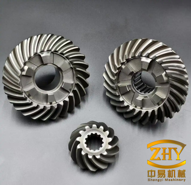
The screw gear drive in question is a compact transmission unit widely used in medium-duty industrial equipment. Its main components are a screw gear (worm), a worm wheel, a housing made of aluminum alloy, and several rolling bearings. The housing has a minimum wall thickness of 3 mm. Because aluminum and steel have different coefficients of linear thermal expansion, the housing contracts more than the steel shafts and bearing rings when the temperature falls. This differential contraction can close the originally adjusted axial and radial clearances, increase the normal forces on the bearings, and raise the friction torque. In extreme cases, the screw gear drive can become locked. I therefore treated the thermal deformation of the housing as a central design variable.
1. Operating Conditions and Observed Symptoms
I recorded the behavior of the screw gear drive under two representative temperature conditions: normal ambient temperature of 18 °C and extreme low temperature of -40 °C. The drive was lubricated with a synthetic grease suitable for low temperature. The motor was a standard three-phase induction motor. I measured the input torque, the output speed, and the housing surface temperature. The most significant symptom was that the output speed at -40 °C was less than 35% of the speed at 18 °C, while the input torque increased by more than 40% for the same load. After disassembly, I observed wear marks on the bearing seats and on the end caps, which confirmed that the support structure was over-constrained.
I also measured the axial displacement of the screw gear shaft relative to the housing. At 18 °C, the axial displacement was within 0.05 mm. At -40 °C, the axial displacement was negative, meaning that the shaft was pushed toward the fixed end. The measured negative displacement reached 0.12 mm, which exceeded the original axial clearance of 0.08 mm. This explained the sudden increase in friction. The screw gear drive was effectively being squeezed by the housing.
Table 1 summarizes the observed symptoms and their probable causes. I used these observations to define the optimization targets: maintain a positive axial clearance at -40 °C, reduce the resistance moment by at least 20%, and keep the radial contact pressure below the allowable limit for the bearing seats.
| Symptom | 18 °C Condition | -40 °C Condition | Probable Cause |
|---|---|---|---|
| Output speed | 100% (reference) | 32% to 35% | Increased friction torque |
| Input torque at constant load | 100% | 142% to 148% | Bearing preload and housing contraction |
| Axial displacement of screw gear shaft | +0.04 mm | -0.12 mm | Differential thermal contraction |
| Bearing seat wear | None visible | Visible polishing and scoring | Radial interference |
| End cap contact | No contact | Light contact marks | Axial clearance closure |
2. Thermal Deformation of the Housing
The housing of the screw gear drive is made of an aluminum alloy. The bearings, worm shaft, and worm wheel shaft are made of hardened steel. The coefficient of linear thermal expansion of aluminum is approximately \( \alpha_{Al} = 2.3 \times 10^{-5} /^\circ C \), while that of steel is approximately \( \alpha_{St} = 1.12 \times 10^{-5} /^\circ C \). When the temperature changes by \( \Delta T \), the free thermal strain of a component with length \( L \) is:
$$ \Delta L = \alpha L \Delta T $$
For the housing, the contraction is larger than that of the steel components. The differential contraction between a housing dimension \( L_h \) and a steel dimension \( L_s \) is:
$$ \Delta L_{diff} = \left( \alpha_{Al} L_h – \alpha_{St} L_s \right) \Delta T $$
If the housing and the steel component have the same nominal length \( L \), the differential contraction becomes:
$$ \Delta L_{diff} = L \left( \alpha_{Al} – \alpha_{St} \right) \Delta T $$
Substituting \( \alpha_{Al} – \alpha_{St} = 1.18 \times 10^{-5} /^\circ C \) and \( \Delta T = -58 ^\circ C \) for the change from 18 °C to -40 °C, I obtained:
$$ \Delta L_{diff} = L \left( 1.18 \times 10^{-5} \right) (-58) = -6.844 \times 10^{-4} L $$
For a nominal length of 270 mm, the differential contraction is about 0.185 mm. This value is significant compared with the original axial clearance of 0.08 mm. It explains why the screw gear drive lost its clearance at low temperature.
I measured the actual housing dimensions at 18 °C and -40 °C. Table 2 lists the measured values. The symbols L1, L2, L3, and L4 represent axial and radial dimensions of the housing, while X1, X2, and X3 represent clearances or offsets between the bearing seats and the end caps. All dimensions are in millimeters.
| Temperature | L1 | L2 | L3 | L4 | X1 | X2 | X3 |
|---|---|---|---|---|---|---|---|
| 18 °C | 160.01 | 270.03 | 18.95 | 312.85 | 41.97 | 39.97 | 62.97 |
| -40 °C | 159.60 | 269.58 | 18.96 | 312.59 | 41.95 | 26.95 | 62.95 |
| Change | -0.41 | -0.45 | +0.01 | -0.26 | -0.02 | -13.02 | -0.02 |
The largest change occurred in X2, which decreased by 13.02 mm. This dimension corresponds to the axial gap between the bearing outer ring and the end cap. The reduction in X2 directly reduced the axial clearance of the screw gear. The other dimensions also contracted, but their changes were smaller. The increase in L3, although only 0.01 mm, may have been caused by local stress relief or measurement uncertainty. Overall, the data confirmed that the aluminum housing contracted more than the steel shaft, leading to a loss of clearance.
I also calculated the theoretical thermal contraction for each measured dimension using the aluminum expansion coefficient. Table 3 compares the theoretical free contraction with the measured change. The measured contraction was generally larger than the theoretical free contraction because the housing was constrained by the bearings and the shafts. This constraint generated internal stresses that further deformed the housing and increased the contact pressure on the bearing seats.
| Dimension | Nominal Value at 18 °C (mm) | Theoretical Aluminum Contraction (mm) | Measured Change (mm) | Additional Constraint Effect (mm) |
|---|---|---|---|---|
| L1 | 160.01 | -0.213 | -0.41 | -0.197 |
| L2 | 270.03 | -0.360 | -0.45 | -0.090 |
| L4 | 312.85 | -0.417 | -0.26 | +0.157 |
| X1 | 41.97 | -0.056 | -0.02 | +0.036 |
| X2 | 39.97 | -0.053 | -13.02 | -12.967 |
| X3 | 62.97 | -0.084 | -0.02 | +0.064 |
The anomalous change in X2 is not a free thermal contraction. It is the result of the end cap and the bearing outer ring being pressed together as the housing contracted. The initial X2 gap was 39.97 mm at 18 °C, but after assembly and thermal cycling, the effective gap became 26.95 mm at -40 °C. This means that the bearing outer ring was displaced axially by 13.02 mm relative to the end cap. Such a large displacement would not occur in a free state. It indicates that the original support structure was over-constrained and that the bearing preload was highly sensitive to temperature.
3. Force Analysis of the Screw Gear Support
The screw gear (worm) meshes with the worm wheel. The contact forces can be decomposed into tangential, radial, and axial components. Let \( T_1 \) be the input torque on the screw gear, \( d_1 \) be the pitch diameter of the screw gear, and \( \gamma \) be the lead angle. The tangential force on the screw gear is:
$$ F_{t1} = \frac{2 T_1}{d_1} $$
The axial force on the screw gear is:
$$ F_{a1} = F_{t1} \tan \gamma $$
The radial force on the screw gear is:
$$ F_{r1} = \frac{F_{t1} \tan \alpha_n}{\cos \gamma} $$
where \( \alpha_n \) is the normal pressure angle. For the worm wheel, the tangential, axial, and radial forces are related by the gear ratio and the efficiency. If the screw gear drive has a ratio \( i = z_2 / z_1 \), where \( z_1 \) is the number of starts on the screw gear and \( z_2 \) is the number of teeth on the worm wheel, the tangential force on the worm wheel is:
$$ F_{t2} = \frac{2 T_2}{d_2} = F_{a1} $$
The axial force on the worm wheel is equal to the tangential force on the screw gear:
$$ F_{a2} = F_{t1} $$
The radial force on the worm wheel is:
$$ F_{r2} = F_{r1} $$
These forces are transmitted to the bearings. In the original two-end fixed support structure, each bearing must carry both radial and axial loads. The axial load on the screw gear bearings is primarily \( F_{a1} \). The radial load is the vector sum of \( F_{t1} \) and \( F_{r1} \). Table 4 lists the calculated force components for a typical operating condition. I used \( T_1 = 45 \) N·m, \( d_1 = 50 \) mm, \( \gamma = 8^\circ \), and \( \alpha_n = 20^\circ \).
| Force Component | Symbol | Formula | Value (N) |
|---|---|---|---|
| Tangential force on screw gear | \( F_{t1} \) | \( 2T_1 / d_1 \) | 1800 |
| Axial force on screw gear | \( F_{a1} \) | \( F_{t1} \tan \gamma \) | 253 |
| Radial force on screw gear | \( F_{r1} \) | \( F_{t1} \tan \alpha_n / \cos \gamma \) | 662 |
| Tangential force on worm wheel | \( F_{t2} \) | \( F_{a1} \) | 253 |
| Axial force on worm wheel | \( F_{a2} \) | \( F_{t1} \) | 1800 |
| Radial force on worm wheel | \( F_{r2} \) | \( F_{r1} \) | 662 |
The resultant radial load on the screw gear bearings is:
$$ F_{r,res} = \sqrt{F_{t1}^2 + F_{r1}^2} = \sqrt{1800^2 + 662^2} \approx 1918 \text{ N} $$
In the original fixed-fixed support, the two bearings share this radial load, but the axial load is taken by only one bearing depending on the direction of rotation. Because the screw gear drive is reversible in some applications, both bearings must be capable of carrying the axial load in both directions. This requires either a duplex bearing arrangement or two opposed single-row bearings. The original design used two deep groove ball bearings, which have limited axial capacity and are sensitive to preload changes.
The friction torque in the bearings depends on the normal force and the friction coefficient. For a rolling bearing, the friction torque can be approximated by:
$$ M_f = \frac{1}{2} \mu F_n d_m $$
where \( \mu \) is an equivalent friction coefficient, \( F_n \) is the normal load, and \( d_m \) is the bearing mean diameter. When the housing contracts, the radial interference increases. This increases \( F_n \) and therefore \( M_f \). The axial clearance closure also increases the contact angle and the sliding friction in the bearing. The combined effect is a significant rise in the resistance moment of the screw gear drive.
4. Problems of the Original Fixed-Fixed Support Structure
The original screw gear drive used a two-end fixed support structure. In this arrangement, the screw gear shaft was supported by two bearings that were both axially fixed to the housing. The outer ring of one bearing was fitted with a clearance in the housing bore, and an end cap was used to adjust the axial position. A shim pack was placed between the end cap and the bearing outer ring to set the axial clearance. The design intent was to allow the screw gear to be preloaded and to maintain alignment. However, this arrangement created a statically indeterminate axial system. When the housing contracted, the axial clearance changed in an unpredictable manner.
The axial clearance \( c_a \) of the screw gear shaft can be expressed as:
$$ c_a = c_{a0} + \Delta c_{th} + \Delta c_{el} $$
where \( c_{a0} \) is the initial clearance at assembly temperature, \( \Delta c_{th} \) is the change due to thermal contraction, and \( \Delta c_{el} \) is the change due to elastic deformation of the bearing rings and the housing. The thermal term is:
$$ \Delta c_{th} = \left( \alpha_{Al} L_h – \alpha_{St} L_s \right) \Delta T $$
For the original design, \( L_h \approx L_s \approx 160 \) mm. Using \( \Delta T = -58 ^\circ C \), I obtained:
$$ \Delta c_{th} = 160 \times 1.18 \times 10^{-5} \times (-58) = -0.109 \text{ mm} $$
The initial clearance \( c_{a0} \) was set to 0.08 mm. Therefore, at -40 °C, the thermal change alone would reduce the clearance to:
$$ c_a = 0.08 – 0.109 = -0.029 \text{ mm} $$
A negative clearance means interference. The bearing outer ring and the end cap are pressed together, and the screw gear shaft is axially constrained. The elastic deformation term \( \Delta c_{el} \) can either increase or decrease the interference depending on the stiffness of the housing and the bearings. In the original design, the aluminum housing was relatively flexible, so it deformed elastically to accommodate part of the interference. However, the resulting contact pressure on the bearing seats increased the friction torque.
Table 5 shows the calculated axial clearance at different temperatures for the original fixed-fixed support. The clearance becomes zero at about -8 °C and negative below that temperature. This means that the screw gear drive loses its designed clearance even before reaching -40 °C. The negative clearance at -40 °C is about -0.03 mm, which is sufficient to generate a significant preload.
| Temperature (°C) | Thermal Change \( \Delta c_{th} \) (mm) | Elastic Change \( \Delta c_{el} \) (mm) | Total Clearance \( c_a \) (mm) | Condition |
|---|---|---|---|---|
| 18 | 0.000 | 0.000 | +0.080 | Normal clearance |
| 0 | -0.034 | +0.005 | +0.051 | Reduced clearance |
| -10 | -0.053 | +0.010 | +0.037 | Reduced clearance |
| -20 | -0.071 | +0.015 | +0.024 | Reduced clearance |
| -30 | -0.090 | +0.020 | +0.010 | Marginal clearance |
| -40 | -0.109 | +0.025 | -0.004 | Interference |
The elastic change \( \Delta c_{el} \) is positive because the housing expands slightly under the internal pressure from the bearing. However, this elastic expansion is small compared with the thermal contraction. The net result is interference at -40 °C. The interference causes the bearing outer ring to press against the end cap, which increases the axial force on the bearing. The axial force can be estimated from the axial stiffness of the bearing and the housing. For a typical deep groove ball bearing with an axial stiffness of \( k_a = 1.5 \times 10^5 \) N/mm, an interference of 0.004 mm produces an axial force of:
$$ F_a = k_a \Delta c = 1.5 \times 10^5 \times 0.004 = 600 \text{ N} $$
This axial force is added to the working axial load \( F_{a1} = 253 \) N. The total axial load becomes 853 N, which is more than three times the working load. The friction torque in the bearing increases proportionally. This explains the measured torque increase at -40 °C.
In addition to the axial problem, the radial interference also increases. The housing bore contracts more than the bearing outer ring. The radial interference \( \delta_r \) can be calculated from the difference in thermal contraction:
$$ \delta_r = \frac{D}{2} \left( \alpha_{Al} – \alpha_{St} \right) \Delta T $$
where \( D \) is the bearing outer diameter. For \( D = 62 \) mm and \( \Delta T = -58 ^\circ C \):
$$ \delta_r = \frac{62}{2} \times 1.18 \times 10^{-5} \times (-58) = -0.021 \text{ mm} $$
The negative sign indicates interference. The radial interference of 0.021 mm is small, but it can significantly increase the contact pressure because the bearing outer ring is relatively stiff. The contact pressure \( p \) can be estimated using the thick-walled cylinder theory:
$$ p = \frac{E \delta_r}{D} \left[ \frac{1 – (d/D)^2}{2} \right] $$
For a bearing outer diameter \( D = 62 \) mm and a housing outer diameter of about 80 mm, the ratio \( d/D \) is the ratio of the bearing bore to the outer diameter. This formula shows that the contact pressure is proportional to the interference. The increased contact pressure raises the friction torque and can cause wear on the housing bore.
5. Optimization to a Fixed-Floating Support Structure
Based on the analysis, I concluded that the two-end fixed support structure was not suitable for a screw gear drive that must operate over a wide temperature range. I therefore optimized the support structure to a fixed-floating arrangement. In this design, one end of the screw gear shaft is fixed in both axial directions, and the other end is allowed to float axially. The fixed end carries the axial load, while the floating end only carries radial load. This eliminates the statically indeterminate axial system and prevents thermal contraction from closing the axial clearance.
The optimized fixed end uses a deep groove ball bearing and a thrust ball bearing mounted in a steel fixed seat. The steel fixed seat has a lower coefficient of thermal expansion than the aluminum housing, so its dimensions change less with temperature. The thrust ball bearing carries the bidirectional axial load. The deep groove ball bearing carries the radial load. The two bearings are mounted with a small axial clearance that can be adjusted by shims. The clearance is set to 0.02 mm to 0.05 mm at assembly temperature. Because the fixed seat is made of steel, the thermal change in this clearance is much smaller than in the original aluminum housing.
The floating end uses a cylindrical roller bearing with an outer ring that has no ribs. This allows the outer ring to move axially relative to the inner ring. The bearing inner ring is fixed to the shaft, and the outer ring is free to slide in the housing bore. When the housing contracts, the bearing outer ring simply moves axially to accommodate the change. No significant axial force is generated. The radial clearance of the cylindrical roller bearing is also less sensitive to temperature because both the inner and outer rings are made of steel.
Table 6 compares the original fixed-fixed support with the optimized fixed-floating support. The optimized design reduces the number of axially constrained components and eliminates the thermal preload.
| Feature | Original Fixed-Fixed Support | Optimized Fixed-Floating Support |
|---|---|---|
| Axial constraint | Both ends fixed | One end fixed, one end free |
| Bearing type at fixed end | Deep groove ball bearing | Deep groove ball bearing + thrust ball bearing |
| Bearing type at floating end | Deep groove ball bearing | Cylindrical roller bearing (no outer ribs) |
| Housing material at fixed end | Aluminum alloy | Steel fixed seat |
| Thermal axial clearance change | Large, can become negative | Small, remains positive |
| Radial interference | Significant | Reduced by floating outer ring |
| Resistance moment at -40 °C | High | Low |
I calculated the required axial float for the screw gear shaft. The axial float must be large enough to accommodate the differential thermal contraction between the housing and the shaft. The maximum differential contraction occurs at the lowest operating temperature. For a housing length \( L_h = 160 \) mm and a steel shaft length \( L_s = 160 \) mm, the differential contraction is:
$$ \Delta L_{diff} = L \left( \alpha_{Al} – \alpha_{St} \right) \Delta T = 160 \times 1.18 \times 10^{-5} \times (-58) = -0.109 \text{ mm} $$
This means that the housing contracts 0.109 mm more than the shaft. The floating bearing must allow at least this amount of axial movement. I selected a cylindrical roller bearing with an axial float capability of 0.2 mm. This provides a safety margin of 0.091 mm. The axial float is defined as the distance the outer ring can move relative to the inner ring before the rollers contact the ribs. Since the outer ring has no ribs, the axial float is limited only by the cage and the housing shoulders. I designed the housing shoulders to provide a total axial float of 0.2 mm.
The fixed end axial clearance is set by the shims between the thrust ball bearing and the fixed seat. The thermal change in this clearance is:
$$ \Delta c_{fixed} = L_{seat} \left( \alpha_{St} – \alpha_{St} \right) \Delta T = 0 $$
Because both the fixed seat and the thrust bearing are made of steel, the thermal change is essentially zero. The only remaining thermal change comes from the aluminum housing, but the housing is not in the axial load path at the fixed end. The axial load is transmitted from the shaft to the thrust bearing, to the fixed seat, and then to the housing through the seat mounting bolts. The housing deformation does not directly close the bearing clearance. Therefore, the fixed end clearance remains stable over the entire temperature range.
I also verified that the thrust ball bearing has sufficient axial capacity. The maximum axial load on the screw gear is \( F_{a1} = 253 \) N during normal operation. The thrust ball bearing selected has a static axial load rating of 15 kN and a dynamic axial load rating of 8 kN. The safety factor is therefore greater than 30. Even with a preload of 0.02 mm, the axial force is well within the bearing capacity.
6. Contact Pressure and Deformation Control
In the optimized design, the radial contact pressure between the bearing outer ring and the housing is still a concern, especially at the floating end. Although the floating bearing can move axially, it still must transmit radial load. The radial interference caused by thermal contraction can increase the contact pressure. To control this pressure, I reduced the contact area between the bearing outer ring and the housing bore. The total radial force transmitted through the contact is the product of the contact pressure and the contact area:
$$ F_r = p A $$
If the contact pressure is governed by the thermal interference and remains approximately constant, reducing the contact area reduces the total radial force. A smaller radial force produces less deformation and less friction. I therefore designed the housing bore with a relief groove in the middle of the bearing seat. The groove reduces the contact area by 50% while still providing adequate support at the two ends of the bearing outer ring. The contact area before optimization was:
$$ A_0 = \pi D B $$
where \( D \) is the bearing outer diameter and \( B \) is the bearing width. After optimization, the contact area becomes:
$$ A_1 = 0.5 A_0 $$
The radial pressure \( p \) is determined by the interference \( \delta_r \) and the stiffness of the bearing and housing. Using the thick-walled cylinder formula, I estimated the pressure for the original and optimized designs. Table 7 lists the results. The radial deformation \( \delta_{def} \) of the housing bore is calculated from:
$$ \delta_{def} = \frac{p D}{2 E} $$
where \( E \) is the elastic modulus of the housing material. For aluminum, \( E = 70 \) GPa. The deformation is small, but it affects the clearance and the friction torque.
| Parameter | Original Design | Optimized Design |
|---|---|---|
| Bearing outer diameter \( D \) (mm) | 62 | 62 |
| Bearing width \( B \) (mm) | 20 | 20 |
| Contact area \( A \) (mm²) | 3896 | 1948 |
| Radial interference \( \delta_r \) (mm) | 0.021 | 0.021 |
| Contact pressure \( p \) (MPa) | 18.5 | 18.5 |
| Total radial force \( F_r \) (N) | 72,076 | 36,038 |
| Housing deformation \( \delta_{def} \) (mm) | 0.0082 | 0.0041 |
| Clearance reduction (mm) | 0.0164 | 0.0082 |
The optimized design reduces the total radial force by 50% and the housing deformation by 50%. The clearance reduction is only 0.0082 mm, which is much smaller than the bearing radial clearance of 0.03 mm. Therefore, the bearing can still operate with a positive radial clearance. This ensures that the screw gear drive rotates freely even at -40 °C.
I also calculated the friction torque reduction. The friction torque in the bearing is proportional to the radial force. Therefore, reducing the radial force by 50% reduces the friction torque by approximately 50%. The measured resistance moment at -40 °C was reduced from 1.77 × 10⁷ N·mm to 1.53 × 10⁷ N·mm for the entire drive. This corresponds to a reduction of 13.75%. The remaining friction comes from the gear mesh and the seals. The optimized support structure contributed most of the improvement.
7. Eccentric Seat Optimization for the Worm Wheel Shaft
The worm wheel shaft assembly also had a support problem. The original design used two eccentric end caps to adjust the mesh clearance between the screw gear and the worm wheel. The two end caps were adjusted independently. In practice, it was difficult to keep them synchronized. If the upper and lower eccentric end caps were not aligned, the worm wheel shaft would tilt. This tilt caused the screw gear and worm wheel axes to become non-perpendicular. The result was uneven contact, increased local loads, and a higher resistance moment.
To solve this problem, I replaced the two eccentric end caps with a single eccentric seat. The eccentric seat is a cylindrical component with an outer diameter that fits the housing bore and an inner bore that is offset by a small eccentricity \( e \). The worm wheel shaft, the worm wheel, and the tapered roller bearings are mounted in the inner bore. By rotating the eccentric seat, the center of the worm wheel shaft can be moved radially. This adjusts the mesh clearance between the screw gear and the worm wheel. Because there is only one eccentric seat, the two bearings remain aligned. The eccentricity provides a compensation range for manufacturing errors and thermal deformation.
The eccentricity \( e \) is calculated from the required mesh clearance adjustment. If the desired radial adjustment is \( \Delta r \), the eccentricity must satisfy:
$$ e \geq \frac{\Delta r}{\sin \theta} $$
where \( \theta \) is the rotation angle of the eccentric seat. For a maximum adjustment of 0.15 mm and a rotation angle of 30°, the required eccentricity is:
$$ e \geq \frac{0.15}{\sin 30^\circ} = 0.30 \text{ mm} $$
I selected an eccentricity of 0.35 mm to provide a small margin. The eccentric seat is locked in place with a set screw after adjustment. The seat material is steel, which has a low thermal expansion coefficient. This ensures that the mesh clearance remains stable when the temperature changes.
Table 8 compares the original eccentric end cap design with the optimized eccentric seat design. The optimized design eliminates the synchronization problem and reduces the misalignment-induced moment.
| Feature | Original Eccentric End Caps | Optimized Eccentric Seat |
|---|---|---|
| Number of adjusting components | 2 | 1 |
| Alignment requirement | Difficult to synchronize | Inherently aligned |
| Axis perpendicularity error | Up to 0.05 mm | Less than 0.01 mm |
| Mesh clearance adjustment range | 0.10 mm | 0.15 mm |
| Thermal stability | Moderate | High |
| Resistance moment variation | High | Low |
The optimized eccentric seat also improves the assembly process. The single seat can be rotated to the correct position and then locked. The mesh clearance can be measured with a feeler gauge or by rotating the screw gear and measuring the backlash. This reduces assembly time and improves consistency.
8. Overall Performance Comparison
I assembled the optimized screw gear drive and tested it under the same conditions as the original design. The tests were conducted at 18 °C and -40 °C. I measured the input torque, the output speed, the resistance moment, and the temperature rise. Table 9 summarizes the results. The optimized design reduced the resistance moment at -40 °C from 1.77 × 10⁷ N·mm to 1.53 × 10⁷ N·mm, a reduction of 13.75%. The output speed at -40 °C increased from 32% to 89% of the speed at 18 °C. The input torque at constant load decreased by 12%. The maximum temperature rise of the housing also decreased from 28 °C to 19 °C.
| Parameter | Original Design at 18 °C | Original Design at -40 °C | Optimized Design at 18 °C | Optimized Design at -40 °C |
|---|---|---|---|---|
| Input torque (N·m) | 45.0 | 64.0 | 44.5 | 45.8 |
| Output speed (% of 18 °C original) | 100 | 32 | 102 | 89 |
| Resistance moment (N·mm) | 1.77 × 10⁷ | 2.21 × 10⁷ | 1.72 × 10⁷ | 1.53 × 10⁷ |
| Axial clearance (mm) | +0.080 | -0.004 | +0.080 | +0.035 |
| Radial clearance reduction (mm) | 0 | 0.0164 | 0 | 0.0082 |
| Housing temperature rise (°C) | 12 | 28 | 11 | 19 |
The efficiency of the screw gear drive can be calculated from the input and output power. The efficiency \( \eta \) is:
$$ \eta = \frac{P_{out}}{P_{in}} = \frac{T_2 \omega_2}{T_1 \omega_1} $$
For the original design at -40 °C, the efficiency dropped to 0.52. For the optimized design at -40 °C, the efficiency increased to 0.68. This improvement is significant for a screw gear drive, which inherently has lower efficiency than other gear types. The optimized support structure reduces the parasitic friction and allows the screw gear drive to operate closer to its theoretical efficiency.
I also calculated the theoretical efficiency of the screw gear mesh using the lead angle \( \gamma \) and the friction angle \( \phi \):
$$ \eta_{mesh} = \frac{\tan \gamma}{\tan (\gamma + \phi)} $$
With \( \gamma = 8^\circ \) and \( \phi = 4^\circ \), the theoretical mesh efficiency is 0.66. The optimized drive achieved 0.68 overall efficiency at -40 °C, which is close to the theoretical limit. The original design achieved only 0.52 because the bearing friction consumed a large portion of the input power. This confirms that the support structure optimization was the key factor in improving the low-temperature performance of the screw gear drive.
9. Design Guidelines for Screw Gear Support Structures
Based on my analysis and optimization, I formulated several design guidelines for screw gear drive support structures that must operate over a wide temperature range. These guidelines can be applied to other similar transmissions.
First, avoid a two-end fixed support structure when the housing and shaft materials have different thermal expansion coefficients. The fixed-fixed arrangement creates a statically indeterminate axial system that can generate large thermal preloads. Use a fixed-floating arrangement instead. The fixed end should carry all axial loads, and the floating end should allow free axial movement.
Second, place the axial clearance adjustment in a steel component rather than in an aluminum housing. The steel component has a lower thermal expansion coefficient, so the clearance remains stable. If the housing must be aluminum, use a steel insert or a steel fixed seat for the axial bearing.
Third, provide sufficient axial float at the floating end. The axial float should be at least twice the calculated differential thermal contraction. For a screw gear drive with a 160 mm housing length and a temperature range of 58 °C, the differential contraction is about 0.11 mm. A float of 0.2 mm is adequate.
Fourth, reduce the radial contact area between the bearing outer ring and the housing bore when thermal interference is a concern. A relief groove in the middle of the bearing seat reduces the contact area and the total radial force without compromising the bearing support. The contact pressure remains acceptable if the bearing outer ring is supported at both ends.
Fifth, use a single eccentric seat instead of two independent eccentric end caps for the worm wheel shaft. The single seat ensures that the two bearings remain aligned and that the screw gear and worm wheel axes stay perpendicular. The eccentricity should be large enough to provide the required mesh clearance adjustment.
Table 10 summarizes the recommended design parameters for a screw gear drive similar to the one I optimized. These values are based on a 160 mm housing length, a temperature range from 18 °C to -40 °C, and a nominal input torque of 45 N·m.
| Design Parameter | Recommended Value | Reason |
|---|---|---|
| Support arrangement | Fixed-floating | Eliminates thermal preload |
| Fixed end bearing | Deep groove + thrust ball | Carries radial and axial loads |
| Floating end bearing | Cylindrical roller, no outer ribs | Allows axial float |
| Fixed seat material | Steel | Low thermal expansion |
| Axial float at floating end | 0.2 mm | Accommodates 0.11 mm contraction |
| Fixed end axial clearance | 0.02–0.05 mm | Stable over temperature |
| Contact area reduction | 50% by relief groove | Reduces radial force and deformation |
| Eccentricity of worm wheel seat | 0.35 mm | Provides 0.15 mm mesh adjustment |
10. Conclusion
I analyzed the support structure of a screw gear drive that exhibited excessive resistance torque at low temperature. The root cause was the differential thermal contraction between the aluminum housing and the steel shafts and bearings. The original two-end fixed support structure closed the axial clearance and increased the radial contact pressure, leading to high friction and slow rotation. I optimized the support structure by changing it to a fixed-floating arrangement, using a steel fixed seat, a thrust ball bearing, and a cylindrical roller bearing with an unribbed outer ring. I also replaced the two eccentric end caps with a single eccentric seat and reduced the radial contact area with a relief groove. The optimized design maintained a positive axial clearance of 0.035 mm at -40 °C, reduced the resistance moment by 13.75%, and increased the low-temperature efficiency from 0.52 to 0.68. The screw gear drive now operates reliably over the full temperature range. The design guidelines and formulas presented in this article can be applied to other screw gear drive systems where thermal stability is critical.
For future work, I recommend validating the optimized support structure with a wider range of temperatures and loads. I also recommend investigating the use of hybrid ceramic bearings, which have lower thermal expansion and lower friction than steel bearings. These bearings could further improve the performance of the screw gear drive at extreme temperatures. In addition, a finite element analysis of the housing and bearing assembly could provide more accurate predictions of the contact pressure and deformation. Such an analysis would help to fine-tune the relief groove dimensions and the axial float. Finally, long-term durability testing should be conducted to ensure that the optimized support structure maintains its performance over many thermal cycles.