
I investigate the transmission efficiency of a lockable screw gear limited-slip differential. The screw gears in this differential provide smooth transmission, favorable meshing characteristics, and high friction. My goal is to elevate the transmission efficiency by analyzing the basic structure and functions of the differential, calculating the power losses from sliding and rolling friction for a single pair of externally meshed screw gears, and then determining the overall efficiency. I compare my computed results with two other methods from the literature to prove correctness. I then include the effects of bearing efficiency and oil stirring efficiency to obtain a theoretical value for the overall differential efficiency. Finally, I use ADAMS software to simulate the differential efficiency and validate the theoretical value.
Keywords: differential; screw gears; transmission efficiency
1. Introduction
The differential is one of the most important components in an automobile, and its performance directly determines the off-road passability of the vehicle. A conventional differential allows different speeds between the left and right wheels but often suffers from the problem that it cannot distribute torque effectively when one wheel loses traction. To overcome this limitation, a lockable screw gear limited-slip differential has been designed and developed. This differential uses screw gears, which have the advantages of stable transmission, good meshing behavior, and large friction forces. It can automatically lock and unlock under various driving conditions, including straight driving, cornering, muddy and slippery roads, and off-road operation. The lockable screw gear differential solves the awkward situation of ordinary differentials that can differentiate speed but not torque. To further improve the off-road performance of this differential, I focus on improving its transmission efficiency.
In this work, I analyze the structure and working principle of the differential, calculate the meshing efficiency of the screw gears, and then compute the overall transmission efficiency. I validate my calculation method by comparing it with two other methods from the literature. I also build a virtual prototype in ADAMS and simulate the transmission efficiency to provide comparative data and a reference for future experimental analysis on a test bench.
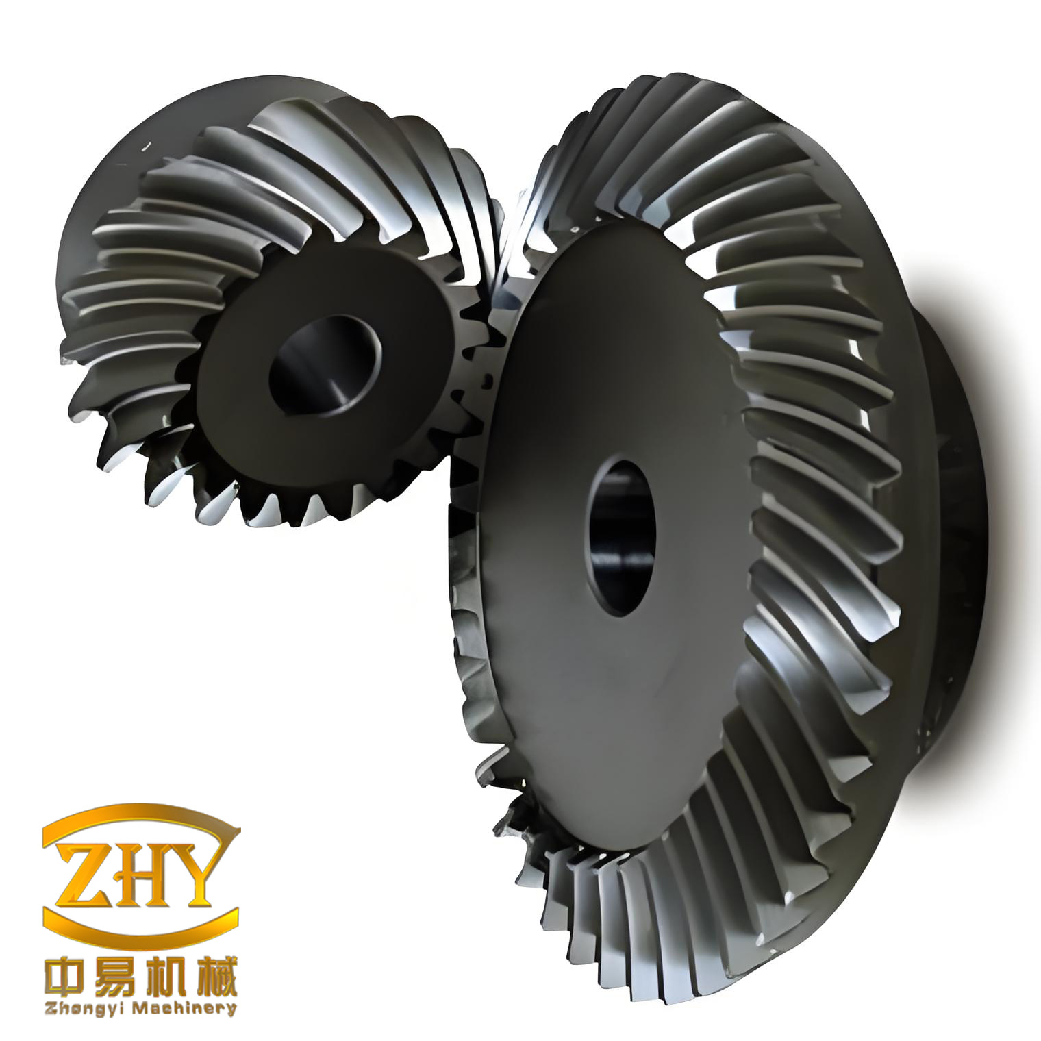
2. Basic Composition and Working Principle
The lockable screw gear limited-slip differential can achieve automatic locking and unlocking, and its structure is not complex, resulting in relatively low maintenance costs. Unlike traditional limited-slip differentials, this differential can distribute torque to the normal wheel through pairs of screw gears installed inside the housing. This changes the passive transfer of a small amount of torque in traditional limited-slip differentials and achieves a significant leap from simply limiting slip to actively transferring power.
2.1 Basic Structure
The lockable screw gear limited-slip differential mainly consists of the differential housing, planetary gears, side gears, inner and outer cams, centrifugal blocks, centrifugal gear shafts, release flyweights, release flyweight shaft friction plates, end covers, and other components. Three pairs of planetary gears are symmetrically arranged on the left and right half shafts and mesh with the side gears. The locking device and the locking release device use centrifugal force through a series of actions of the centrifugal gear shaft, centrifugal block, inner and outer cams, and release flyweights to achieve automatic locking and unlocking of the vehicle. The main components are summarized in Table 1.
| Component | Function |
|---|---|
| Differential housing | Encloses the internal parts and transmits torque |
| Planetary screw gears | Mesh with side gears and distribute torque |
| Side gears | Connected to half shafts and transmit torque to wheels |
| Inner and outer cams | Engage during locking to restrict relative motion |
| Centrifugal blocks | Move outward under centrifugal force to initiate locking |
| Centrifugal gear shafts | Transmit motion from side gears to centrifugal blocks |
| Release flyweights | Disengage locking when vehicle speed increases |
| Friction plates | Provide frictional torque during locking |
| End covers | Support shafts and close the housing |
2.2 Working Principle of the Differential
When the vehicle is driving straight, the left and right planetary screw gears and side gears rotate together with the housing, and the torque is equally distributed to the left and right half shafts. When the vehicle turns, for example to the right, the left side gear speed increases, driving the meshing planetary screw gears to rotate in reverse. This causes the right planetary screw gears to rotate forward and drive the right side gear in reverse, thereby achieving differential speed between the left and right wheels and completing the turn.
When one side of the vehicle slips, the speed of the slipping side gear increases. Because the helix angle of the screw gears is large, a large internal friction force is generated during meshing, which hinders the increase in wheel speed. In addition, the meshing screw gears generate a large axial force toward the end cover and a radial force pointing to the outer wall of the planetary gear hole. These three resistance forces jointly limit the increase in wheel speed and achieve limited slip.
When one wheel of the vehicle, for example the right wheel, spins freely, the side gear drives the cam and the centrifugal shaft to rotate at high speed. The centrifugal block overcomes the force of the compression spring and swings outward to engage with the release flyweight. At this moment, the centrifugal shaft and the outer cam no longer rotate at high speed. However, because the side gear and the inner cam are still moving at high speed, the inner cam drives the outer cam to move toward the end cover. Under the squeezing action of the friction plate group and the end cover, the outer cam drives the inner cam and thus the right half shaft stops moving and returns to the same speed as the differential housing, achieving locking. When the vehicle escapes from the difficult situation and the vehicle speed increases to a certain level, the release flyweight overcomes the engagement with the centrifugal shaft and centrifugal block under the action of centrifugal force, and the vehicle returns to the initial state.
3. Transmission Efficiency Analysis of the Differential
I take the first pair of externally meshed screw gears in the differential as an example to calculate the meshing efficiency of the gear pair. I then combine the oil stirring efficiency and bearing efficiency to obtain the theoretical transmission efficiency of the differential.
3.1 Calculation of the Meshing Efficiency of Externally Meshed Screw Gears
The study of meshing efficiency mainly involves the calculation of power losses from sliding friction and rolling friction. Some literature only analyzes the meshing efficiency of spur gears, and some calculation methods only consider sliding friction power loss. I borrow the calculation method for internal meshing efficiency from the literature and derive the calculation formula for the external meshing efficiency of screw gears. I also consider the rolling friction power loss, which makes the final result closer to actual experimental results.
Externally meshed screw gears differ from spur gears. During transmission, they do not mesh along the entire tooth width at the same time. Instead, they gradually enter and leave meshing along the tooth width direction. A standard externally meshed screw gear transmission has a meshing surface with tooth width \(B\). The gear starts meshing from the front end face and begins to separate at the rear end face at point \(E’\). This is equivalent to the screw gear having an additional meshing length \(\Delta L\) during the meshing process.
3.1.1 Calculation of Sliding Friction Power Loss
I first analyze the end face of the gear. A screw gear can be regarded as many thin-walled spur gears rotated by a helix angle and superimposed. By integrating the sliding friction work loss expression of the end face spur gear, I derive the sliding friction work loss expression for externally meshed screw gears based on the geometric relationship between screw gears and spur gears.
Because the meshing point changes instantaneously, the meshing efficiency also changes continuously. I adopt the method of first calculating the instantaneous efficiency and then integrating along the meshing line to obtain the sliding friction work loss. The instantaneous efficiency at the meshing point of the gear is
$$ \eta_s = \frac{P_d}{P_f} = \begin{cases} \frac{1 – f \tan \alpha_2}{1 – f \tan \alpha_1}, & \alpha_1 > \alpha_2, \\ \frac{1 + f \tan \alpha_2}{1 + f \tan \alpha_1}, & \alpha_1 < \alpha_2, \end{cases} $$
where \(f\) is the friction coefficient, \(f = \tan \varphi\), and \(\alpha_1\), \(\alpha_2\) are the angles between the instantaneous velocity and the meshing line.
The friction coefficient \(f\) can be selected according to simplified methods in gear handbooks, but this is not accurate enough. To make the final efficiency closer to the actual value, I use the calculation method for the friction coefficient of externally meshed screw gears from tribology principles.
In calculating the total meshing process, I divide it into two parts, \(PB_1\) and \(PB_2\), and integrate separately. Similar to the literature, I set the distance from point \(P\) to the meshing point as \(x\). From the relationship between the external meshing point and the pressure angle, at meshing point \(k\):
$$ \tan \alpha_1 = \frac{r_{b1} \tan \alpha – x}{r_{b1}}, \quad \tan \alpha_2 = \frac{r_{b2} \tan \alpha + x}{r_{b2}}, \quad PB_2 = r_{b1} (\tan \alpha – \tan \alpha_{a1}). $$
At meshing point \(k’\):
$$ \tan \alpha_1 = \frac{r_{b1} \tan \alpha + x}{r_{b1}}, \quad \tan \alpha_2 = \frac{r_{b2} \tan \alpha – x}{r_{b2}}, \quad PB_1 = r_{b2} (\tan \alpha – \tan \alpha_{a2}). $$
Here, \(r_{b1}\) and \(r_{b2}\) are the base circle radii of the driving and driven gears, and \(\alpha_{a1}\) and \(\alpha_{a2}\) are the angles formed by the base circle, the addendum circle radius, and the meshing line.
The meshing efficiency of the gear along the meshing line \(PB_1\) is
$$ S_1 = \int_{0}^{PB_1} \eta_s \, dx = \int_{0}^{r_{b2} (\tan \alpha – \tan \alpha_{a2})} \frac{1 – f \frac{r_{b2} \tan \alpha – x}{r_{b2}}}{1 – f \frac{r_{b1} \tan \alpha + x}{r_{b1}}} \, dx. $$
The meshing efficiency of the gear along the meshing line \(PB_2\) is
$$ S_2 = \int_{0}^{PB_2} \eta_s \, dx = \int_{0}^{r_{b1} (\tan \alpha – \tan \alpha_{a1})} \frac{1 + f \frac{r_{b2} \tan \alpha + x}{r_{b2}}}{1 + f \frac{r_{b1} \tan \alpha – x}{r_{b1}}} \, dx. $$
where \(B_1 B_2 = PB_1 + PB_2\), and \(PB_1\), \(PB_2\) are given above.
Combining with the geometric relationships of involute gears:
$$ i_{21} = \frac{r_{b1}}{r_{b2}}, \quad r_{b1} = \frac{m z_1 \cos \alpha}{2}, \quad \alpha_{a1} = \arccos \frac{r_{b1}}{r_{a1}} = \arccos \frac{z_1 \cos \alpha}{z_1 + 2 h_a^*}, \quad \alpha_{a2} = \arccos \frac{r_{b2}}{r_{a2}} = \arccos \frac{z_2 \cos \alpha}{z_2 – 2 h_a^*}, $$
where \(h_a^*\) is the addendum height coefficient.
For externally meshed screw gear transmission, I correct the calculation according to the geometric relationship between spur gears and screw gears: \(m_n = m_t \cos \beta\). Substituting this into the meshing efficiency calculation formula, the relevant parameter values are given in Table 2.
| Parameter | Planetary gear | Side gear |
|---|---|---|
| Number of teeth, \(z\) | 6 | 18 |
| Addendum height coefficient, \(h_a^*\) | 1 | 1 |
| Helix angle, \(\beta\) (deg) | 45 | 45 |
| Transverse module, \(m_t\) (mm) | 3.75 | 3.75 |
| Transverse pressure angle, \(\alpha_t\) (deg) | 20 | 20 |
| Tooth width, \(B\) (mm) | 5.21 | 2.89 |
I calculate the meshing efficiency of the externally meshed screw gears considering only sliding friction power loss:
$$ \eta_{\text{sliding}} = \frac{S_1 + S_2}{B_1 B_2} = 98.15\%. $$
3.1.2 Calculation of Rolling Friction Power Loss
In the actual meshing transmission of gears, the gears are lubricated by oil, so an oil film forms between the tooth profiles, causing relative rolling during gear meshing. Although the rolling friction power loss is relatively small compared with the sliding friction power loss, it still needs to be considered in accurate calculations. The specific calculation formula is
$$ P_R = \frac{9 h V_{Tm} b \times 10^{-2}}{\cos \beta}, $$
where \(h\) is the oil film thickness,
$$ h = \frac{3.07 \xi^{0.57} R^{0.4} (\rho V_{Tm})^{0.71}}{E’^{0.03} \phi^{0.11}}, $$
\(E’\) is the composite elastic modulus, which I take as \(2.1 \times 10^{11}\) Pa; \(\xi\) is the pressure-viscosity coefficient, taken as \(2.2 \times 10^{-8}\) m\(^2\)/N; \(\phi\) is the load coefficient, taken as \(0.4 \times 10^6\) N/m; \(V_{Tm}\) is the average rolling speed during gear meshing:
$$ V_{Tm} = 1.05 \times 10^{-4} n_1 \left[ d_1 \sin \alpha + \frac{1.57 m_n (1 – 1/i_{12}^2) (\varepsilon_1^2 + \varepsilon_2^2)}{\varepsilon_1 + \varepsilon_2} \right], $$
where \(\varepsilon_1\) and \(\varepsilon_2\) are the contact ratios at the beginning and end of meshing. Their values can be obtained from the definition of the contact ratio of externally meshed screw gears in the literature.
The driving work of the screw gear meshing transmission is
$$ P = \int F v \, dt = \int F r_{b1} \omega_1 \, dt = \pi m_t \cos \alpha_t F. $$
Therefore, the influence of rolling friction power loss on the meshing efficiency is
$$ \eta_G = \frac{P_R}{P} = 0.23\%. $$
Finally, the sliding friction efficiency is calculated as \(97.92\%\).
3.2 Comparative Analysis of Meshing Efficiency
To verify the accuracy of my calculation results, I use the methods from two other literature sources to validate the above calculation. One method calculates the sliding friction power loss at the meshing point and integrates along the meshing line to obtain the screw gear meshing efficiency. After calculation, the efficiency is \(98.36\%\). The other method calculates the meshing efficiency of externally meshed screw gears by piecewise integration in the actual meshing interval, and the calculated efficiency is \(98.32\%\). The results of the three methods are shown in Table 3.
| Calculation method | Literature method 1 | Literature method 2 | This work |
|---|---|---|---|
| Meshing efficiency (%) | 98.36 | 98.32 | 97.92 |
From the analysis, it can be seen that the theoretical values calculated by the three methods are not much different, which proves the correctness of my method. In addition, the fact that my method considers rolling friction power loss, making the efficiency slightly lower than the two literature methods, is consistent with actual conditions. In the next step, I need to conduct transmission efficiency experiments on a differential test bench to further verify with actual data.
3.3 Calculation of the Total Transmission Efficiency of the Differential
Because the internal side gears and planetary screw gears of the lockable screw gear limited-slip differential mesh with each other, the gears form a series-connected unit. The total transmission efficiency of a series-connected unit is equal to the product of the transmission efficiencies of the individual components. Therefore, the efficiency of the differential is the product of the transmission efficiencies of each gear pair.
In Section 3.1, I already calculated the meshing efficiency of the first pair of externally meshed screw gears. I only need to consider the oil stirring efficiency and bearing efficiency. In the actual operation of the differential, the power losses from oil stirring efficiency and bearing efficiency are not large. The former is related to the oil immersion depth, speed, oil viscosity, and other factors during gear meshing transmission. In most cases, it is taken as \(0.99\). For bearing efficiency, the transmission mode of the bearing needs to be considered. The efficiency of rolling bearings is generally \(0.99\); the efficiency of sliding bearings is generally \(0.98\) to \(0.99\). The differential bearings used in this work are rolling bearings, so the bearing efficiency is taken as \(0.99\).
I obtain
$$ \eta_1 = \eta_{\text{mesh}} \eta_{\text{oil}} \eta_{\text{bearing}} = 0.9792 \times 0.99 \times 0.99 = 0.9597. $$
Similarly, using my method, I calculate the second and third pairs of screw gears and obtain \(\eta_2 = 98.74\%\) and \(\eta_3 = 96.49\%\). The total transmission efficiency of the differential is
$$ \eta = \eta_1 \eta_2 \eta_3 = 0.9597 \times 0.9874 \times 0.9649 = 0.9144. $$
Thus, the theoretical total transmission efficiency of the differential is \(91.44\%\). The efficiency contributions are summarized in Table 4.
| Pair | Meshing efficiency (%) | Oil stirring efficiency (%) | Bearing efficiency (%) | Combined efficiency (%) |
|---|---|---|---|---|
| First pair | 97.92 | 99 | 99 | 95.97 |
| Second pair | — | — | — | 98.74 |
| Third pair | — | — | — | 96.49 |
| Overall | — | — | — | 91.44 |
4. Simulation Verification of Differential Transmission Efficiency
4.1 Model Import and Parameter Settings
The interface module MECHANISM/Pro can directly open ADAMS/Solver to complete virtual prototype simulation. I use this module to realize the import and data exchange between ADAMS and Pro/ENGINEER. After the model is imported, I add relevant material properties and solid features, and set the parameters. The meshing motion time is set to \(1\) s, the step size is \(1 \times 10^{-4}\), the input shaft driving speed is \(1000\) deg/s, and a load torque of \(615000\) N·mm is added. After specifying the load torque, I further measure the input torque and speed, and use the ratio of output power to input power as the efficiency calculation formula to complete the efficiency calculation.
| Parameter | Value |
|---|---|
| Simulation time | 1 s |
| Step size | \(1 \times 10^{-4}\) |
| Input shaft driving speed | 1000 deg/s |
| Load torque | 615000 N·mm |
| Input shaft | Right half shaft |
4.2 Analysis of Simulation Results
I set the right half shaft as the input shaft. After completing the relevant parameter settings in ADAMS, I obtain the speed and torque diagrams of the input and output components in the ADAMS/PostProcessor module. From the diagrams, it can be seen that the driving speed and rotational speed of the input shaft are fixed at the set values. The rotational speed and torque of the output shaft fluctuate around an average value and tend to be stable.
The differential transmission efficiency curve shows that within the simulation time of 0 to 1 s, the minimum efficiency value reaches about \(84\%\), and the maximum reaches \(98\%\) to \(99\%\). However, overall, the average efficiency fluctuates around \(93\%\). Compared with the calculated result of \(91.44\%\), the error is about \(1.56\%\). This indicates that the simulation results of the software are consistent with the theoretical calculation results, verifying the correctness of the calculation results.
| Source | Efficiency (%) |
|---|---|
| Theoretical calculation | 91.44 |
| ADAMS simulation average | 93.00 |
| Difference | 1.56 |
5. Sensitivity and Discussion
The transmission efficiency of the lockable screw gear limited-slip differential is influenced by many design parameters. The helix angle of the screw gears, the number of teeth, the module, the pressure angle, the tooth width, and the friction coefficient all affect the sliding and rolling friction power losses. In my analysis, I used a helix angle of \(45^\circ\), a transverse module of \(3.75\) mm, and a transverse pressure angle of \(20^\circ\). These values were chosen based on the original design of the differential, but they may not be optimal for maximum efficiency.
For screw gears, a larger helix angle generally increases the axial force and the sliding velocity, which can increase the sliding friction power loss. However, a larger helix angle also increases the contact ratio and can improve the smoothness of transmission. There is a trade-off between efficiency and load-carrying capacity. In future work, I could perform a parametric study to determine the optimal helix angle for this differential application. Table 7 shows a qualitative summary of how key parameters affect efficiency.
| Parameter | Increase in parameter | Effect on sliding loss | Effect on rolling loss | Overall efficiency trend |
|---|---|---|---|---|
| Helix angle, \(\beta\) | Increase | Increase | Increase | Decrease |
| Number of teeth, \(z\) | Increase | Slight increase | Slight decrease | Almost constant |
| Module, \(m_t\) | Increase | Decrease | Increase | Slight increase |
| Pressure angle, \(\alpha_t\) | Increase | Increase | Decrease | Slight decrease |
| Tooth width, \(B\) | Increase | Decrease | Increase | Slight increase |
| Friction coefficient, \(f\) | Increase | Increase | No direct effect | Decrease |
Another important factor is the lubrication condition. The oil film thickness \(h\) depends on the pressure-viscosity coefficient, the composite elastic modulus, the load coefficient, and the average rolling speed. A thicker oil film reduces direct metal-to-metal contact and lowers the friction coefficient, but it also increases the rolling friction power loss because the oil film must be sheared. In my calculation, the rolling friction power loss was only \(0.23\%\) of the driving work, which is relatively small. However, under high-speed or high-load conditions, this loss could become more significant.
The bearing efficiency and oil stirring efficiency also depend on the operating conditions. At high speeds, the oil stirring loss increases because the gears and bearings must churn more oil. The rolling bearing efficiency of \(0.99\) is a typical value for well-lubricated bearings under normal load. If the bearings are preloaded or operate at very high speed, the efficiency could be lower. Similarly, the oil stirring efficiency of \(0.99\) assumes a moderate oil level. If the differential is overfilled with oil, the stirring loss could increase substantially.
My calculation of the total differential efficiency used the product of the efficiencies of the three screw gear pairs. This assumes that the power flows through all three pairs in series. In the actual differential, the power split between the left and right half shafts depends on the driving condition. During straight driving, the planetary screw gears may not rotate relative to the housing, so the meshing losses might be different from those during cornering or slipping. My calculation represents a worst-case or average scenario where all gear pairs are actively meshing. For more accurate prediction, a full system-level simulation that includes the kinematics of the differential under various driving cycles would be necessary.
6. Conclusion
I have analyzed the transmission efficiency of a lockable screw gear limited-slip differential. The main findings are as follows.
1) Taking the first pair of meshing screw gears as an example, I considered both sliding friction and rolling friction power losses and calculated the meshing efficiency of the externally meshed screw gears relatively accurately. The calculated meshing efficiency was \(97.92\%\). I compared this result with two other calculation methods from the literature, and the comparison proved the correctness of my calculation.
2) I imported the three-dimensional model into ADAMS and simulated the differential efficiency using the software. From the efficiency curve after simulation, the average efficiency was about \(93\%\), which shows that the simulation results are consistent with the calculation results. The error compared with the theoretical value remained within \(3\%\).
3) Considering that the selection of differential design parameters can have a certain influence on the final differential efficiency, in future work I can conduct in-depth research on the relevant parameters to provide a reference for improving differential performance. The screw gears are the key components, and optimizing their geometry and lubrication will be essential for further efficiency gains.
Overall, the lockable screw gear limited-slip differential achieves a theoretical transmission efficiency of \(91.44\%\), and the ADAMS simulation average of \(93\%\) supports this value. The small difference is attributed to the simplifying assumptions in the analytical model, such as constant friction coefficient and ideal oil film conditions. Experimental validation on a test bench will be the next step to confirm these findings and to refine the efficiency model. The results provide a useful basis for improving the off-road performance of vehicles equipped with this type of differential.
Nomenclature
| Symbol | Description | Unit |
|---|---|---|
| \(\eta_s\) | Instantaneous meshing efficiency | — |
| \(f\) | Friction coefficient | — |
| \(\alpha_1, \alpha_2\) | Angles between velocity and meshing line | rad |
| \(r_{b1}, r_{b2}\) | Base circle radii | mm |
| \(\alpha\) | Pressure angle | rad |
| \(\alpha_{a1}, \alpha_{a2}\) | Addendum circle angles | rad |
| \(z_1, z_2\) | Number of teeth | — |
| \(h_a^*\) | Addendum height coefficient | — |
| \(m_t\) | Transverse module | mm |
| \(m_n\) | Normal module | mm |
| \(\beta\) | Helix angle | rad |
| \(B\) | Tooth width | mm |
| \(P_R\) | Rolling friction power loss | W |
| \(h\) | Oil film thickness | m |
| \(V_{Tm}\) | Average rolling speed | m/s |
| \(E’\) | Composite elastic modulus | Pa |
| \(\xi\) | Pressure-viscosity coefficient | m\(^2\)/N |
| \(\phi\) | Load coefficient | N/m |
| \(\eta_G\) | Rolling friction efficiency loss | — |
| \(\eta_1, \eta_2, \eta_3\) | Combined efficiencies of gear pairs | — |
| \(\eta\) | Total differential efficiency | — |
The analysis and simulation I have presented demonstrate that the lockable screw gear limited-slip differential can achieve a high transmission efficiency while providing the desired limited-slip and locking functions. The screw gears are central to this performance, and their careful design and lubrication are critical. By continuing to optimize the screw gear parameters and validating the results experimentally, it will be possible to further improve the efficiency and off-road capability of vehicles using this differential technology.