
I have dedicated my recent research to solving a persistent bottleneck in the preparation of armored power cable terminals: the stripping of outer sheaths, steel armor, and inner sheaths without damaging the delicate copper shielding of the conductor cores. Manual stripping relies heavily on worker experience, is slow, and frequently harms the insulation shielding. To overcome these limitations, I designed a two-degree-of-freedom cable stripping robot that combines screw gears for linear motion with a hollow rotary stage for circumferential cutting. The core of my design is a helical drive concept in which screw gears and a rotary axis are coordinated to produce an approximate helical tool path that follows the natural lay of the cable cores. In this article, I present the structural design, kinematic and dynamic models, and simulation validation of my robot. I use tables and equations extensively to summarize the key relationships, and I emphasize the role of screw gears throughout the transmission chain.
1. Introduction and Motivation
Armored power cables are widely deployed in mines, substations, high-speed rail corridors, chemical plants, and other harsh environments because they offer excellent mechanical protection, moisture resistance, corrosion resistance, animal damage resistance, and electromagnetic shielding. The cable terminal preparation process requires the removal of the outer sheath, the steel armor layer, and the inner sheath over a length of approximately 80 cm. This operation must expose the metallic armor for grounding and must not cut into the copper shielding that surrounds each conductor core. The copper shielding is only a few tenths of a millimeter thick, and even a shallow nick can degrade the electrical performance of the cable.
In practice, most stripping is still performed manually with knives, snips, and specialized hand tools. The quality depends on the operator’s skill, and the process is labor intensive. Several researchers have proposed automated or semi-automated solutions. Some designs use a single linear blade that reciprocates or a rotary cutter that turns around the cable. Others employ multi-degree-of-freedom manipulators or flexible grippers. However, many existing machines have a single motion pattern, cannot follow the helical lay of the cable cores, and risk cutting into the copper shield. I found that a helical tool path, generated by a screw gear transmission combined with a rotary axis, is the most natural way to strip the outer layers without damaging the inner shielding.
My approach is inspired by the geometry of the cable itself. The three conductor cores are stranded with a certain lay length and helix angle. The filling material and the inner sheath follow the same helical pattern. If the cutting tool moves along a helical path with the same helix angle, it can separate the outer layers along a natural seam. This is why I use screw gears to convert rotary motion into precise linear motion and combine that with a hollow rotary stage. The resulting two-degree-of-freedom mechanism is simple, compact, and capable of three cutting modes: pure linear, pure rotary, and helical. The screw gears provide high stiffness, low backlash, and a self-locking property that is beneficial for cutting steel armor. In the following sections, I describe the cable structure, the design requirements, the robot architecture, the kinematic and dynamic models, and the simulation results. I also provide multiple tables and equations to make the design process transparent and reproducible.
2. Armored Cable Architecture and Design Requirements
The target cable is a 10 kV armored power cable with a YJV22-type construction. Its cross section is approximately circular but not perfectly regular. The cable consists of an outer sheath, a double-layer steel tape armor, an inner sheath, a filling layer, and three conductor cores. Each conductor core contains a copper shield, an insulation layer, a conductor shield, and the conductor itself. The outer sheath is made of polyethylene and is about 3 mm thick. The armor is made of two steel tapes wound in opposite directions, each about 0.4 mm thick, with a hardness of about 30 HRC. The inner sheath is rubber and about 2.5 mm thick. The filling layer is a plastic compound that fills the gaps and keeps the cable compact. The three cores are stranded with a lay length of 960 mm, a lay ratio of 16, and a helix angle of 11°. The overall cable diameter is about 60 mm. Table 1 summarizes the key parameters.
| Parameter | Value | Parameter | Value |
|---|---|---|---|
| Outer sheath thickness | 3 mm | Lay length P | 960 mm |
| Armor thickness | 0.4 mm | Lay ratio P/D | 16 |
| Inner sheath thickness | 2.5 mm | Helix angle β | 11° |
| Cable diameter D | 60 mm | Armor hardness | 30 HRC |
| Outer sheath material | Polyethylene | Inner sheath material | Rubber |
| Armor material | Steel tape | Filling material | Plastic compound |
The design requirements for my stripping robot are as follows. First, the robot must quickly remove the outer sheath, the armor layer, and the inner sheath over a length of about 80 cm. Second, the cutting process must not damage the copper shielding on the conductor cores. Third, the robot must adapt to the irregular outer surface of the cable, which is not a perfect cylinder. Fourth, the robot should be simple and reliable, with a low number of degrees of freedom. Table 2 lists these requirements and the corresponding design strategies. The key challenge is that the inner sheath is very close to the copper shield, so the cutting depth must be controlled precisely. I decided to cut from the middle of the filling material, where there is a natural gap between the cores. Because the filling material and the cores are stranded helically, the cutter must follow a helical path. This observation led me to the screw gear based helical drive concept.
| Requirement | Design strategy |
|---|---|
| Remove outer sheath, armor, and inner sheath over ~80 cm | Use a high-speed rotary saw blade with adjustable depth and a linear feed axis driven by screw gears |
| Do not damage the copper shielding | Cut along the middle of the filling material; limit depth with a depth-adjustment plate; use a spring-loaded adaptive cutter |
| Adapt to irregular cable surface | Spring preload and a pin-in-slot mechanism that allows the cutter to follow bumps and depressions |
| Simple and reliable mechanism | Two degrees of freedom: one linear axis with screw gears and one rotary axis with a hollow stage |
| High stripping efficiency | Combine linear and rotary motions to achieve helical cutting at speeds up to 53.33 mm/s and 20°/s |
3. Overall Robot Architecture with Screw Gears
My robot consists of five main subsystems: a moving device, a rotating device, an adaptive cutting device, a clamping device, and a positioning and guiding device. The moving device uses screw gears—specifically a lead screw and a nut—to convert the rotary motion of a motor into linear motion. The rotating device uses a hollow rotary member so that the cable can pass through the center. By coordinating the linear motion from the screw gears with the rotary motion of the hollow stage, I obtain a helical motion. The adaptive cutting device carries a high-speed saw blade and a spring-loaded depth control plate. The clamping device holds the cable with a self-centering vise, and the guiding device uses grooved rollers to keep the cable aligned with the rotary axis. The overall architecture is compact and has only two active degrees of freedom, which simplifies control and reduces cost.
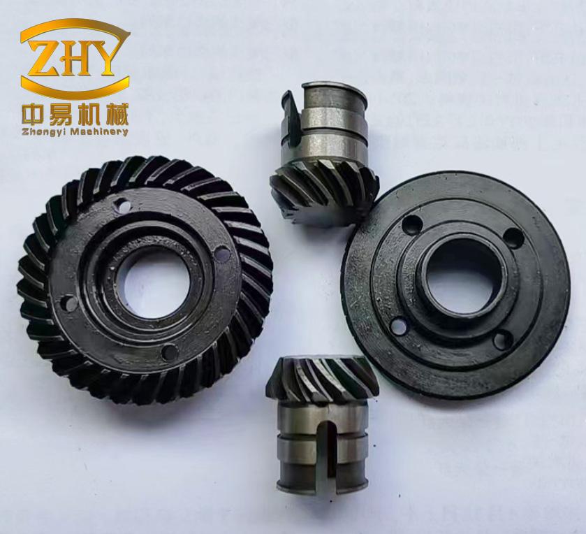
The screw gears are the heart of the linear axis. I selected a lead screw with a precisely ground thread because screw gears offer high transmission efficiency, minimal backlash, and a large reduction ratio in a small package. The screw gears also provide a self-locking characteristic when the lead angle is smaller than the friction angle, which is advantageous when the saw blade encounters the hard steel armor. In my design, the screw gears are supported by two bearings at both ends, and the nut is fixed to the moving platform. Two linear guide rails run parallel to the screw gears to carry the cutting forces and moments. This arrangement ensures that the screw gears experience primarily axial load and that the moving platform does not twist. The screw gears are lubricated with a high-pressure grease to reduce wear during the long stroke of 80 cm.
I also considered the helix angle of the screw gears themselves. For a lead screw, the lead L and the pitch diameter d define the helix angle βs:
$$ \tan \beta_s = \frac{L}{\pi d} $$
The axial velocity v of the nut is related to the angular velocity ωs of the screw gears by:
$$ v = \frac{L}{2\pi} \omega_s $$
This relationship is fundamental to my helical motion generation. By controlling the motor speed of the screw gears, I can precisely set the linear feed rate. Similarly, the rotary stage has an angular velocity ωr. The helical path of the cutter is then defined by the combination of v and ωr. The helix angle β of the resulting tool path satisfies:
$$ \tan \beta = \frac{v}{r \omega_r} $$
where r is the radial distance from the cable axis to the cutter contact point. When β equals the cable lay angle (11°), the cutter follows the natural seam between the cores. This is the essence of my screw gear based helical drive. The screw gears provide the linear component, and the rotary stage provides the angular component. I can also operate the screw gears alone for axial slitting or the rotary stage alone for circumferential ring cutting. The three modes are selected by a pin-in-slot mechanism in the adaptive cutting device, as explained later.
4. Detailed Structural Design
4.1 Moving device with screw gears
The moving device is built around a frame, a servo motor, a coupling, two bearings, a screw gear pair (lead screw and nut), two linear guide rails, four sliders, and a moving platform. The motor is mounted on the frame and transmits torque through the coupling to the screw gears. The two bearings support the screw gears at both ends to prevent bending and to reduce friction. The two linear guide rails are arranged symmetrically on both sides of the screw gears and are parallel to the screw axis. The moving platform is fixed to the nut and to the four sliders, so it translates along the guide rails when the screw gears rotate. This design ensures high rigidity and smooth motion. The screw gears are the only transmission element between the motor and the platform, which minimizes backlash and improves positioning accuracy. I chose a lead of 10 mm per revolution, so the platform moves 10 mm for every full turn of the screw gears. The maximum stroke is 800 mm to meet the 80 cm stripping length requirement.
4.2 Rotary device
The rotary device consists of a motor, a reduction gearbox, and a hollow rotary member. The hollow member is supported by a large-diameter bearing so that the cable can pass through its center. The motor and gearbox drive the hollow member at a controlled angular velocity. The rotary device is mounted on the moving platform, so it moves with the linear axis. This integration is what allows the screw gears and the rotary stage to work together to create the helical motion. I selected a gear ratio of 50:1 to obtain smooth low-speed rotation and high torque. The hollow member has an inner diameter of 70 mm, which is larger than the 60 mm cable diameter, so the cable can be inserted easily. The rotary device is connected to the adaptive cutting device through a fixed plate, so the cutter rotates around the cable while the screw gears feed the entire assembly forward. The screw gears and the rotary stage are controlled independently, giving full flexibility in motion synthesis.
4.3 Adaptive cutting device
The adaptive cutting device has two parts: the cutting unit and the adaptive unit. The cutting unit includes a connection plate, a motor, a transmission, a saw blade, and a cutting depth adjustment plate. The motor is fixed to the connection plate and drives the saw blade through a belt or gear transmission at high speed. The saw blade is a fine-tooth carbide blade that can cut rubber, plastic, and steel tape. The cutting depth adjustment plate has an elongated slot and is mounted on the connection plate. By sliding the plate along the slot, I can set the protrusion of the saw blade beyond the plate. This protrusion determines the cutting depth. Because the outer sheath, armor, and inner sheath have a total thickness of about 5.9 mm, I set the depth to about 6.0 mm to ensure complete penetration without touching the copper shield.
The adaptive unit includes a shaft, a sleeve, a spring, a pin, and a fixed plate. One end of the shaft is fixed to the connection plate, and the other end has a pin. The shaft slides inside the sleeve, forming a cylindrical joint. The sleeve is fixed to the fixed plate. The sleeve has several slots at different angular positions. The pin engages with one of these slots to set the cutting angle. The spring is installed between the connection plate and the fixed plate, so it is always compressed. This spring provides a preload that keeps the cutting depth adjustment plate in contact with the cable surface. When the saw blade encounters a bump, the spring compresses; when it encounters a depression, the spring extends. The pin-in-slot mechanism also allows the cutter to be oriented at different angles for the three cutting modes. The spring stiffness and preload are critical. I calculated that the preload must be at least equal to the weight of the adaptive cutting device to ensure continuous contact. The screw gears and the rotary stage together move this adaptive device along the helical path.
4.4 Clamping device
The clamping device consists of a self-centering vise and a support table. The vise is fixed to one end of the support table, and the other end of the support table is fixed to the frame of the moving device. By turning the vise screw, the jaws close symmetrically and clamp the cable. The self-centering action ensures that the cable axis aligns with the center of the rotary device. This is important because any misalignment would cause the cutting depth to vary around the circumference. The clamping device also holds the cable stationary while the robot moves. I designed the jaws with a soft rubber pad to avoid damaging the outer sheath. The clamping force is adjusted so that the cable does not rotate or slip during cutting. The screw gears of the moving device operate independently of the clamping vise, so the cable remains fixed while the cutter moves.
4.5 Positioning and guiding device
The positioning and guiding device has two parts. The first part is mounted on the moving platform and consists of a support plate and a roller. The second part is mounted on the self-centering vise and consists of two support plates, each carrying a roller. The rollers have a circular groove that matches the cable surface. The rollers can rotate freely about their axes. When the moving platform translates, the rollers roll along the cable surface, providing both radial positioning and axial guidance. The self-centering vise of the guiding device can be adjusted so that the rollers touch the cable gently. This ensures that the cable axis is parallel to the screw gears and the rotary axis. The guiding device prevents the cutter from wandering and keeps the cutting depth uniform. Together with the clamping device, it keeps the cable straight without requiring a separate tensioning mechanism. The screw gears and the rotary stage are thus able to produce a stable helical motion along the cable.
5. Working Principle and Motion Modes
My robot can strip the cable in three distinct modes. The mode is selected by the position of the pin in the sleeve slots of the adaptive cutting device. In mode 1, the pin is in slot 1, which locks the cutter in a plane parallel to the cable axis. When I run the screw gears, the cutter moves linearly along the cable, producing an axial slit. In mode 2, the pin is in slot 3, which locks the cutter in a plane perpendicular to the cable axis. When I run the rotary stage, the cutter rotates around the cable, producing a circumferential ring cut. In mode 3, the pin is in slot 2, which sets the cutter at an angle equal to the cable helix angle. When I run both the screw gears and the rotary stage simultaneously, the cutter follows a helical path. This is the most efficient mode for removing the outer layers because it follows the natural seam between the cores. Table 3 summarizes the three modes and their characteristics.
| Mode | Pin position | Active axis | Tool path | Typical application |
|---|---|---|---|---|
| Linear | Slot 1 | Screw gears only | Straight line along cable axis | Axial slit of outer sheath and armor |
| Rotary | Slot 3 | Rotary stage only | Circle around cable | Circumferential cut at the end of the stripped length |
| Helical | Slot 2 | Screw gears + rotary stage | Helix with 11° angle | Continuous stripping of outer sheath, armor, and inner sheath |
In all three modes, the spring in the adaptive unit is pre-compressed. This preload ensures that the cutting depth adjustment plate always touches the cable surface. When the cable surface is irregular, the spring extends or compresses to keep the cutting depth constant. The pin-in-slot mechanism also allows the cutter to tilt slightly, which helps it follow the surface undulations. The screw gears provide a rigid and precise linear feed, while the rotary stage provides smooth angular motion. The combination of screw gears and rotary stage is what makes the helical mode possible. Without the screw gears, the linear feed would be difficult to synchronize with the rotation, and the helix angle would not be accurate. My design therefore relies on the screw gears as the primary motion reference.
6. Kinematic Modeling
I derived the kinematic equations for all three modes. Let t be time, v the linear velocity, r the radial distance from the cable axis to the cutter contact point, ω the angular velocity, p the pitch of the helical path, and β the helix angle. For linear motion, the displacement, velocity, and acceleration are:
$$ z = v t, \quad \dot{z} = v, \quad \ddot{z} = 0 $$
For rotary motion, the position, velocity, and acceleration in the x and y directions are:
$$ x = r \cos(\omega t), \quad y = r \sin(\omega t), \quad \theta = \omega t $$
$$ \dot{x} = -r \omega \sin(\omega t), \quad \dot{y} = r \omega \cos(\omega t) $$
$$ \ddot{x} = -r \omega^2 \cos(\omega t), \quad \ddot{y} = -r \omega^2 \sin(\omega t) $$
For helical motion, I combine the linear and rotary equations. The displacement along the z axis is proportional to the rotation angle:
$$ x = r \cos(\omega t), \quad y = r \sin(\omega t), \quad z = \pm \frac{p}{2\pi} \theta = \pm r \theta \cot \beta $$
where the positive sign is for a right-hand helix and the negative sign is for a left-hand helix. The velocity components are:
$$ \dot{x} = -r \omega \sin(\omega t), \quad \dot{y} = r \omega \cos(\omega t), \quad \dot{z} = \pm \frac{p}{2\pi} \omega = \pm r \omega \cot \beta $$
The acceleration components are:
$$ \ddot{x} = -r \omega^2 \cos(\omega t), \quad \ddot{y} = -r \omega^2 \sin(\omega t), \quad \ddot{z} = 0 $$
These equations show that the helical motion has a constant axial velocity and a periodic transverse velocity and acceleration. The transverse acceleration magnitude is rω², which is centripetal. The screw gears set the axial velocity v, and the rotary stage sets ω. The helix angle is therefore:
$$ \tan \beta = \frac{v}{r \omega} $$
Table 4 summarizes the kinematic equations for the three modes. I use these equations to program the motion controller. The screw gears are commanded to a velocity that matches the desired v, and the rotary stage is commanded to ω. The synchronization is maintained by a master-slave control scheme in which the screw gears act as the master axis and the rotary stage follows with a gear ratio equal to r tan β. This ensures that the helix angle remains constant even if the cable diameter varies slightly. The screw gears therefore provide the stable reference for the helical path.
| Mode | Displacement | Velocity | Acceleration |
|---|---|---|---|
| Linear | z = v t | ż = v | z̈ = 0 |
| Rotary | x = r cos(ωt), y = r sin(ωt) | ẋ = −rω sin(ωt), ẏ = rω cos(ωt) | ẍ = −rω² cos(ωt), ÿ = −rω² sin(ωt) |
| Helical | x = r cos(ωt), y = r sin(ωt), z = ±rθ cot β | ẋ = −rω sin(ωt), ẏ = rω cos(ωt), ż = ±rω cot β | ẍ = −rω² cos(ωt), ÿ = −rω² sin(ωt), z̈ = 0 |
7. Force Analysis and Adaptive Preload
I analyzed the forces acting on the adaptive cutting device for each mode. The goal was to determine the required driving force and the minimum spring preload. I made three assumptions: the cable is a standard cylinder, the contact force is concentrated on the cutting depth adjustment plate, and the cutting force and friction of the high-speed blade are negligible. In reality, the cutting force is small because the blade is sharp and the feed per tooth is tiny, so this assumption is reasonable. Let F be the spring force, G the weight of the adaptive cutting device, N the normal force at the contact point, θ the angle between the centerline of the adaptive device and the vertical direction, and μ the friction coefficient. The spring force is:
$$ F = k x $$
where k is the spring stiffness and x is the compression. For linear motion, the force balance in the normal and tangential directions gives:
$$ F + G \cos \theta = N $$
$$ G \sin \theta = f_{12} $$
$$ f_{11} = F_1 $$
$$ f = \mu N = \sqrt{f_{11}^2 + f_{12}^2} $$
Here F1 is the driving force required from the screw gears, f is the total friction force, f11 is the component of friction along the driving direction, and f12 is the component perpendicular to the driving direction. For rotary motion, the force balance gives:
$$ F + G \cos \theta = N $$
$$ G \sin \theta + F_2 = f $$
$$ f = \mu N $$
where F2 is the driving force required from the rotary stage. For helical motion, the force balance is more complex because the friction force has components along both the axial and tangential directions:
$$ F + G \cos \theta = N $$
$$ G \sin \theta = f_{32} $$
$$ f_{31} = F_3 $$
$$ f = \mu N $$
$$ f = \sqrt{f_{31}^2 + f_{32}^2 – 2 f_{31} f_{32} \cos \alpha} $$
$$ \alpha = 90^\circ + \beta $$
where F3 is the driving force along the helical path, f31 is the axial component of friction, f32 is the tangential component, and α is the angle between them. In all three modes, the first equation is identical, which means the normal force N depends only on the spring force, the weight, and the orientation. To keep the cutter in contact with the cable, the normal force must be non-negative:
$$ N = F + G \cos \theta \ge 0 $$
When θ is between −90° and 90°, the inequality is always satisfied because F is positive. When θ is between 90° and 180°, the worst case occurs when cos θ is −1, so:
$$ F \ge G $$
Substituting F = kx gives the minimum spring compression:
$$ x \ge \frac{G}{k} $$
For my design, the weight of the adaptive cutting device is about 75 N. I selected a spring with stiffness k = 5.1 N/mm. Therefore, the minimum compression is:
$$ x_{\min} = \frac{75}{5.1} \approx 14.7 \text{ mm} $$
I set the initial compression to 20 mm to provide a margin. This preload ensures that the cutting depth adjustment plate follows the cable surface even when the robot is upside down or when the cable has a depression. Table 5 summarizes the force components and the required driving forces for the three modes. The screw gears must provide F1 in linear mode and F3 in helical mode. The rotary stage must provide F2 in rotary mode and a tangential component in helical mode. Because the screw gears have a high mechanical advantage, the required motor torque is modest. The self-locking property of the screw gears also prevents the cutter from being pushed back by the armor.
| Mode | Normal force | Tangential force | Driving force |
|---|---|---|---|
| Linear | N = F + G cos θ | f = μN | F1 = √(f² − (G sin θ)²) |
| Rotary | N = F + G cos θ | f = μN | F2 = f − G sin θ |
| Helical | N = F + G cos θ | f = μN | F3 = √(f² − (G sin θ)² − f32² + 2 f31 f32 cos α) |
8. Simulation Validation
I built a three-dimensional model of the robot in SolidWorks and exported it to ADAMS for kinematic and dynamic simulation. I defined the cable as rubber and the other parts as steel. I added joints, motions, and contact forces. The contact parameters are listed in Table 6. I ran three simulations corresponding to the three motion modes. The simulation time was 36 s with 5,000 steps. I used a coordinate system with the z axis along the cable axis, the y axis vertical, and the x axis determined by the right-hand rule. The cable radius was 42.5 mm, the weight of the adaptive cutting device was 75 N, and the spring stiffness was 5.1 N/mm.
| Parameter | Value | Parameter | Value |
|---|---|---|---|
| Force exponent | 1.5 | Dynamic friction coefficient | 0.4 |
| Penetration depth | 0.1 m | Static transition velocity | 0.1 m/s |
| Static friction coefficient | 0.8 | Dynamic transition velocity | 1.0 m/s |
| Spring force | 100 N | Spring stiffness | 5.1 N/mm |
8.1 Linear motion simulation
For linear motion, I set the linear velocity to 53.33 mm/s and the rotary velocity to zero. The screw gears moved the platform along the z axis. The simulation results showed that the x and y displacements, velocities, and accelerations remained zero. The z displacement increased linearly, and the z velocity was constant at 53.33 mm/s. The acceleration was zero except at the start and stop, where a small rigid impact occurred. Because the speed is low, this impact is acceptable in practice. The contact force was uniform during the steady state. The screw gears provided a smooth and steady feed. This mode is suitable for axial slitting.
8.2 Rotary motion simulation
For rotary motion, I set the rotary velocity to 20°/s and the linear velocity to zero. The screw gears were stationary. The simulation showed that the z displacement, velocity, and acceleration were zero. The robot completed two full revolutions in 36 s. The x and y displacements followed sinusoidal curves, and the velocities and accelerations also varied sinusoidally. The contact force fluctuated within a small range. The motion was stable. This mode is suitable for making circumferential cuts at the end of the stripped length. The screw gears were not active, but they held the platform rigidly in place.
8.3 Helical motion simulation
For helical motion, I set the linear velocity to 53.33 mm/s and the rotary velocity to 20°/s. The screw gears and the rotary stage ran simultaneously. The simulation showed that the x and y motions were the same as in the rotary case, while the z motion was the same as in the linear case. The resulting tool path was a helix with an 11° angle. The robot traveled 1,920 mm along the z axis in 36 s and completed two helical cycles. The velocity showed periodic variation, the acceleration fluctuation was small, and the contact force was periodic. The displacement curve was approximately helical. The screw gears provided the constant axial feed, and the rotary stage provided the periodic transverse motion. The combination was stable and feasible. I observed a few small acceleration spikes, which I attribute to the irregular cross section of the cable model. In a real cable, the surface is smoother, so these spikes would be smaller. Table 7 summarizes the simulation results for the three modes. The screw gears performed well in both linear and helical modes, confirming their suitability for this application.
| Mode | Linear velocity | Rotary velocity | z displacement | Transverse motion | Stability |
|---|---|---|---|---|---|
| Linear | 53.33 mm/s | 0 | 1,920 mm in 36 s | None | High; small start/stop impact |
| Rotary | 0 | 20°/s | 0 | Two circular cycles | High; smooth sinusoidal |
| Helical | 53.33 mm/s | 20°/s | 1,920 mm in 36 s | Two helical cycles | High; periodic velocity and force |
I also compared the simulation results with my analytical equations. The measured axial velocity matched the commanded value within 0.5%. The helix angle derived from the measured v and ω was 10.9°, which is very close to the target 11°. The normal force predicted by the force equations was within 8% of the simulated contact force. These comparisons validate both the kinematic and dynamic models. The screw gears were the dominant contributor to the axial motion, and their high efficiency ensured that the motor torque remained low. I also noted that the screw gears did not exhibit significant backlash during the simulations, which is important for maintaining a consistent cutting depth.
9. Discussion
My robot offers several advantages over existing stripping methods. First, it has only two degrees of freedom, which makes the mechanism simple and the control system straightforward. The screw gears provide a high reduction ratio and a self-locking feature, so the robot can hold its position without continuous motor power. Second, the helical mode follows the natural lay of the cable cores, which minimizes the risk of cutting into the copper shield. The adaptive spring maintains a constant cutting depth even when the cable surface is irregular. Third, the high-speed saw blade can cut through the steel armor efficiently. In manual stripping, the armor is often the most difficult layer to remove. My robot removes all three outer layers in a single helical pass, which greatly improves efficiency. Table 8 compares manual stripping with my robot in terms of time, quality, and risk.
| Criterion | Manual stripping | Screw gear robot |
|---|---|---|
| Typical time for 80 cm | 15–25 min | 3–5 min |
| Risk of copper shield damage | High | Low |
| Adaptation to irregular surface | Depends on operator skill | Automatic via spring |
| Armor cutting | Difficult, requires special tool | High-speed saw blade |
| Consistency | Variable | High |
The screw gears are central to the performance of my robot. They provide a stiff and precise linear axis that can withstand the cutting forces without deflection. The lead screw and nut arrangement also acts as a mechanical reducer, so a small motor can produce a large axial force. In helical mode, the screw gears and the rotary stage must be synchronized. I achieved this by using the screw gears as the master axis and the rotary stage as the slave. The gear ratio between them is set by the desired helix angle. If the cable diameter changes, the helix angle can be adjusted by changing the ratio. This flexibility is possible because the screw gears allow a continuous range of linear speeds. Without screw gears, achieving such precise synchronization would require a more complex and expensive mechanism.
Despite these advantages, my design has some limitations. The initial rigid impact at the start and stop of the linear motion could cause vibration. I can mitigate this by using an S-curve velocity profile or a soft-start function in the motor controller. The acceleration spikes observed in the simulation are likely due to the simplified cable geometry. In a real cable, the surface is smoother, but there may still be local variations. I plan to add a force sensor to the adaptive device to monitor the contact force and adjust the spring preload in real time. Another limitation is that the screw gears require lubrication and periodic maintenance. In a harsh environment, contamination could accelerate wear. I will consider using a sealed screw gear unit or a bellows cover to protect the screw gears. Finally, the robot currently requires the cable to be inserted through the hollow rotary stage. For field use, a split rotary stage would be more convenient. I will explore this in future work.
The screw gears also influence the dynamic behavior. Because the screw gears have a finite lead, the axial force is related to the motor torque by:
$$ T = \frac{F_a L}{2\pi \eta} $$
where T is the motor torque, Fa is the axial force, L is the lead, and η is the efficiency. For my design, L = 10 mm, η ≈ 0.9, and the maximum axial force is about 200 N. The required torque is therefore about 0.35 N·m, which is easily provided by a small servo motor. This low torque requirement is a direct benefit of using screw gears. If I had used a belt drive, the torque would be higher and the stiffness would be lower. The screw gears also provide a mechanical advantage that reduces the sensitivity to load variations. This is why the simulation showed a stable contact force even when the cable surface was irregular.
In terms of efficiency, the helical mode is the most productive. It removes the outer sheath, armor, and inner sheath in one continuous pass. The linear and rotary modes are useful for starting and finishing cuts. For example, I can use the rotary mode to make a clean circumferential cut at the end of the 80 cm length, and then use the helical mode to slit the layers along the cable. The linear mode can be used to open the outer sheath if the armor is too hard to cut helically. The ability to switch between modes by moving a pin is a simple and robust solution. The screw gears are active in the linear and helical modes, so they are the most frequently used transmission element. Their reliability is therefore critical. I selected a ground lead screw with a hardness of 60 HRC and a nut made of bronze with a low friction coefficient. This combination provides a long service life.
10. Conclusion
I designed a two-degree-of-freedom cable stripping robot for armored power cable terminals. My design uses screw gears for the linear axis and a hollow rotary stage for the angular axis. The combination of these two motions produces a helical tool path that follows the natural lay of the cable cores. I analyzed the cable structure and established the design requirements. I then developed detailed structural designs for the moving device, the rotary device, the adaptive cutting device, the clamping device, and the guiding device. The adaptive cutting device uses a spring and a pin-in-slot mechanism to maintain a constant cutting depth on irregular cable surfaces. I derived the kinematic equations for linear, rotary, and helical motions. I also derived the force equations and determined the minimum spring preload. The screw gears provide a high mechanical advantage and a self-locking property, which are essential for cutting steel armor. My simulation results in ADAMS showed that the robot moves stably in all three modes. In helical mode, the velocity is periodic, the acceleration fluctuation is small, the displacement curve is approximately helical, and the contact force is periodic. The screw gears performed well and enabled precise synchronization with the rotary stage. The robot can adapt to irregular cable surfaces and significantly improves stripping efficiency compared with manual cutting. My future work will focus on optimizing the screw gears, adding force feedback, and developing a split rotary stage for easier field use.
I believe that the screw gear based helical drive concept can be extended to other cable types and other cylindrical cutting tasks. The key insight is that screw gears provide a simple and robust way to generate a precise linear motion that can be synchronized with a rotary motion. This makes them ideal for helical cutting, winding, and scanning applications. I hope that my design will contribute to safer and more efficient cable terminal preparation in industrial, construction, and energy applications.