
I treat the ZN-type worm and worm wheel in my new-energy vehicle transmission as precision screw gears. These screw gears transmit motion between two crossed axes, normally at 90°, and they let me achieve a large reduction ratio in a small package. The screw gears in the selection, shift, and clutch-control circuits must be quiet, compact, and repeatable because each function depends on controlled speed reduction and torque amplification.
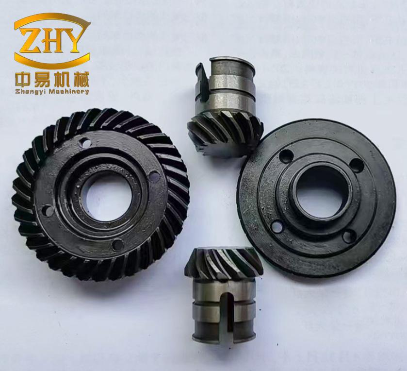
Because the screw gears are crossed-axis components, the tooth surface is a helical ruled surface. In the ZN form, the normal section of the thread groove is straight, while the axial section is slightly convex and the end section is an extended involute. This geometry makes the screw gears manufacturable by turning and grinding, but it also means that tool alignment, wheel dressing, and inspection must be handled with great care. My process plan therefore combines conventional turning, special tool preparation, heat treatment, precision grinding, hobbing, and metrology into one controlled chain.
Functional Role in the Transmission
In my application, the screw gears are not merely reducers. They are part of an electromechanical motion system. A selection motor drives a screw gear reducer, and the reduced output is converted from rotary motion into linear motion through a rack-and-pinion system. The linear motion pulls the shift control shaft and completes the selection action. A shift motor also drives a screw gear reducer, and the output passes through a single-stage gear set before reaching the shift shaft. The clutch-control motor uses another screw gear reducer with a self-locking function so that the clutch can remain disengaged for a long period without continuous motor torque.
The screw gears have a large number of meshing teeth in contact at the same time. This increases overlap, improves motion smoothness, and reduces noise. It also raises the load capacity for a given envelope. However, the same property makes the screw gears sensitive to pitch error, lead error, profile deviation, and center-distance error. When I design the process, I therefore treat the screw gears as a matched pair rather than as two independent parts.
| Function | Motion Path | Key Requirement | Manufacturing Implication |
|---|---|---|---|
| Selection | Motor to screw gears to rack and pinion to shift shaft | Low backlash, smooth motion, compact size | Tight lead and profile control on screw gears |
| Shift | Motor to screw gears to gear stage to shift shaft | High torque density, fast response | Strong tooth flanks, controlled contact pattern |
| Clutch control | Motor to screw gears to self-locking reducer | Self-locking, stable separation state | Lead angle and friction condition must be controlled |
| General transmission | Crossed-axis power transfer | Quiet operation, high ratio, long life | Matched hobbing and grinding of screw gears |
The self-locking behavior of the screw gears can be described by the relationship between lead angle and friction angle. For a first estimate, I use the following condition:
$$\gamma \lt \phi = \arctan \mu$$
With the design lead angle of the screw gears being about 11.3°, the equivalent friction coefficient must be sufficiently high in the selected lubrication and surface condition. This is why the final surface texture, heat treatment, and running-in behavior of the screw gears cannot be separated from the geometric process.
ZN Geometry and Design Parameters
The ZN screw gears have a straight-sided normal profile. I define the basic worm data first, then derive the axial pitch, lead, normal module, and normal pitch. The worm is right-hand and has two starts. The worm wheel is also right-hand and has a modification coefficient that shifts the center distance and contact behavior.
$$m = 1.25 \text{ mm}$$
$$z_1 = 2$$
$$\alpha_n = 20^\circ$$
$$q = 10$$
$$\gamma = 11.3^\circ$$
$$d_1 = q m = 12.5 \text{ mm}$$
$$P_x = \pi m = 3.927 \text{ mm}$$
$$P_z = P_x z_1 = 7.854 \text{ mm}$$
$$\tan \gamma = \frac{P_z}{\pi d_1} = \frac{z_1}{q} = 0.2$$
$$\gamma = \arctan(0.2) = 11.31^\circ$$
$$m_n = m \cos \gamma = 1.226 \text{ mm}$$
$$P_n = \pi m_n = 3.851 \text{ mm}$$
$$s_x = e_x = \frac{P_x}{2} = 1.9635 \text{ mm}$$
$$s_n = e_n = \frac{P_n}{2} = 1.9255 \text{ mm}$$
For the worm wheel, the main parameters are listed below. The wheel indexing diameter is 75 mm, the number of teeth is 60, and the modification coefficient is 0.2. The transmission ratio between the screw gears is therefore 30:1, which is one of the reasons this screw gear pair is attractive for a compact actuator.
$$z_2 = 60$$
$$d_2 = 75 \text{ mm}$$
$$x_2 = 0.2$$
$$i = \frac{n_1}{n_2} = \frac{z_2}{z_1} = 30$$
$$a = \frac{d_1 + d_2}{2} + x_2 m = 44.0 \text{ mm}$$
$$d_{a2} = d_2 + 2m(h_a^* + x_2) = 78.0 \text{ mm}$$
$$d_{a1} = d_1 + 2h_a^* m = 15.0 \text{ mm}$$
| Parameter | Symbol | Value | Remark |
|---|---|---|---|
| Module | m | 1.25 mm | Basic module for the screw gears |
| Worm starts | z1 | 2 | Two-start ZN worm |
| Normal pressure angle | αn | 20° | Straight normal profile |
| Diameter quotient | q | 10 | Controls worm indexing diameter |
| Lead angle | γ | 11.3° | Right-hand screw gears |
| Addendum coefficient | ha* | 1 | Standard value |
| Worm indexing diameter | d1 | 12.5 mm | d1 = q m |
| Axial pitch | Px | 3.927 mm | Px = π m |
| Lead | Pz | 7.854 mm | Pz = Px z1 |
| Normal module | mn | 1.226 mm | mn = m cos γ |
| Normal pitch | Pn | 3.851 mm | Pn = π mn |
| Parameter | Symbol | Value | Remark |
|---|---|---|---|
| Wheel teeth | z2 | 60 | Matched to the ZN worm |
| Wheel indexing diameter | d2 | 75 mm | Nominal value |
| Modification coefficient | x2 | 0.2 | Adjusts center distance and contact |
| Normal pressure angle | αn | 20° | Same as worm |
| Helix direction | — | Right hand | Matched screw gears |
| Transmission ratio | i | 30 | i = z2 / z1 |
| Center distance | a | 44.0 mm | With x2 = 0.2 |
| Wheel addendum diameter | da2 | 78.0 mm | Calculated value |
Process Strategy for the Screw Gears
I separate the process into a worm route and a worm wheel route. The worm is a shaft-like component with a strong heat-treatment and grinding sequence. The worm wheel is a bronze component with turning, drilling, milling, and hobbing operations. The two routes meet only at final inspection and contact-pattern checking. In my experience, the most important decision is not the individual machine but the sequence: every datum must be established before the thread or tooth geometry is generated, and every heat-treatment distortion must be corrected before final metrology.
| Component | Process Route |
|---|---|
| Worm | Material selection → blank turning → center holes → rough turning → finish turning → thread turning → milling → heat treatment → outside-diameter grinding → thread grinding → inspection |
| Worm wheel | Material selection → rough turning → finish turning → drilling → outside-diameter turning → slot milling → hobbing → milling of excess material → inspection |
| Step | Operation | Purpose | Key Control |
|---|---|---|---|
| 1 | Material selection | Provide hard, tough worm body | Alloy steel with suitable hardenability |
| 2 | Blank turning | Create initial cylindrical form | Allowance for heat treatment and grinding |
| 3 | Center holes | Establish axial datum | Runout and center-hole quality |
| 4 | Rough turning | Remove major stock | Uniform allowance, low residual stress |
| 5 | Finish turning | Prepare journals and shoulders | Diameter, shoulder squareness, surface finish |
| 6 | Thread turning | Generate ZN screw gear thread | Normal straight profile, lead, pitch |
| 7 | Milling | Form flats and drive features | Symmetry and angular position |
| 8 | Heat treatment | Harden tooth flanks | Hardness, case depth, distortion |
| 9 | Outside-diameter grinding | Restore bearing journals | Roundness, taper, surface roughness |
| 10 | Thread grinding | Finish screw gear flanks | Profile, lead, pressure angle, surface integrity |
| 11 | Inspection | Verify final screw gears | All drawing requirements |
| Step | Operation | Purpose | Key Control |
|---|---|---|---|
| 1 | Material selection | Provide conformable bronze wheel | Uniform tin-bronze structure |
| 2 | Rough turning | Create end faces and bore | Stock distribution for finishing |
| 3 | Finish turning | Establish bore and face datum | Perpendicularity and concentricity |
| 4 | Drilling | Produce mounting holes | Position, diameter, deburring |
| 5 | Outside-diameter turning | Prepare wheel body for hobbing | Diameter, runout, clamping stability |
| 6 | Slot milling | Create keyway or slot | Width, symmetry, edge quality |
| 7 | Hobbing | Generate worm wheel teeth | Center distance, hob alignment, radial feed |
| 8 | Milling of excess material | Remove hobbing burrs and excess zones | No damage to tooth flanks |
| 9 | Inspection | Verify screw gear pair | Pitch, runout, profile, lead, contact |
Worm Machining Method
The worm is the driving member of the screw gears in my process. I select a hardenable alloy steel and plan for a final hardness of 45–55 HRC on the tooth flanks. The material must be clean, dimensionally stable, and capable of holding a ground profile after heat treatment. The turning operation is not just roughing; it is the first geometric generation of the screw gears. If the thread turning is poor, the grinding wheel will have to remove an uneven layer, and the final lead and profile will suffer.
For thread turning, I modify a standard insert so that the cutting edge produces the required normal straight profile. The tool is set in the normal plane of the thread groove. At the pitch line, the tooth thickness and the groove width are equal in the axial section, so the nominal half-pitch value is the key setting reference.
$$s_x = e_x = \frac{P_x}{2} = 1.9635 \text{ mm}$$
$$s_n = e_n = \frac{P_n}{2} = 1.9255 \text{ mm}$$
| Tool Feature | Value or Setting | Reason |
|---|---|---|
| Normal pressure angle | 20° | Matches ZN screw gears |
| Included angle | 40° | Two times the normal pressure angle |
| Tool placement | Normal to groove centerline | Creates straight normal profile |
| Axial half-pitch reference | 1.9635 mm | Equal tooth and gap at pitch line |
| Normal half-pitch reference | 1.9255 mm | Normal section control |
| Lead angle | 11.31° | Right-hand screw gears |
| Roughing allowance | 0.15–0.25 mm | Leaves stable stock for grinding |
I cut one helix first and leave a controlled allowance. Then I approach the opposite flank and cut the second helix. This alternating strategy reduces cutting pressure and helps me maintain the normal profile. After thread turning, I check the lead, axial pitch, and flank straightness before heat treatment. Any correction is easier before hardening than after hardening.
Heat treatment introduces distortion. I control the furnace cycle, support the worm vertically when possible, and use a fixture if the geometry requires it. After heat treatment, I grind the bearing journals first because they are the datums for thread grinding. The outside-diameter grinding restores concentricity, roundness, and surface finish. Only then do I grind the screw gear flanks.
Thread grinding is the most sensitive operation for the ZN screw gears. The grinding wheel must be dressed to an approximate ZN profile, and the wheel axis must be tilted to the lead angle. I use a diamond dresser and move it along the axial direction to generate the required wheel form. The workpiece is held between two centers, and I indicate the journals to ensure that the screw gear axis is correct. The grinding cycle is divided into roughing, finishing, and spark-out passes.
$$v_s = \frac{\pi D_s n_s}{1000}$$
$$v_w = \frac{\pi d_w n_w}{1000}$$
| Grinding Stage | Infeed per Pass | Purpose |
|---|---|---|
| Roughing | 0.020–0.030 mm | Remove heat-treatment distortion |
| Finishing | 0.005–0.010 mm | Establish final profile and lead |
| Spark-out | 2–3 passes | Improve surface finish and reduce elastic recovery |
| Cooling | Flood coolant | Prevent burn and thermal growth |
Worm Wheel Machining Method
The worm wheel is made from tin bronze because it can run in with the hardened steel worm and form a favorable contact pattern. The bronze wheel is softer than the worm, so it accommodates small alignment errors and distributes load over several teeth. In my process, the wheel bore and face are the primary datums. I finish them before hobbing and then use a dedicated hobbing fixture to preserve concentricity.
The hobbing operation uses a special hob that matches the ZN worm. The hob must have the same module, normal pressure angle, lead angle, and hand as the worm. Before cutting, I align the hob axis and set the center distance. The radial feed is controlled from the tooth tip to the full depth. A typical radial feed range is:
$$f_r = 0.03 \text{ to } 0.05 \text{ mm/r}$$
The kinematic relationship between the hob and the worm wheel is:
$$n_w = \frac{n_h z_h}{z_2}$$
If the hob has two starts, then the wheel rotates at one-thirtieth of the hob speed. This matches the transmission ratio of the final screw gears. The center distance for hobbing is based on the theoretical mounting distance and the modification coefficient:
$$a = \frac{d_h + d_2}{2} + x_2 m$$
With the hob pitch diameter matching the worm indexing diameter, the center distance is 44.0 mm. I verify the actual center distance after the first cut and adjust the contact pattern by controlled changes in center distance or by selecting a suitable modification. After hobbing, I remove burrs carefully. Any heavy deburring can change the effective tooth thickness and damage the screw gears.
| Hobbing Parameter | Value | Control Method |
|---|---|---|
| Hob type | ZN-matched special hob | Same normal profile as worm |
| Hob starts | Matched to worm starts | Preserves ratio and lead |
| Center distance | 44.0 mm nominal | Calculated and verified by contact pattern |
| Radial feed | 0.03–0.05 mm/r | Programmed and monitored |
| Cutting direction | Climb or conventional as validated | Depends on fixture rigidity |
| Cooling | Flood or high-pressure coolant | Controls bronze chip evacuation and temperature |
| Runout after hobbing | As low as possible | Indicate bore and fixture before cutting |
Tooling and Fixtures
I design the tooling around the datums that influence the screw gears. For the worm, the critical fixture is the set of centers and the driving dog. For thread grinding, the centers must be clean, lubricated, and free from damage. For the wheel, the hobbing fixture must center the bore and clamp the face without distorting the bronze body. If the fixture is weak, the wheel will spring during cutting, and the final tooth thickness will vary around the circumference.
| Operation | Fixture or Tooling | Critical Design Point |
|---|---|---|
| Worm turning | Self-centering chuck, spring collet, live center | Rigid support and axial alignment |
| Worm thread turning | Modified insert and normal-plane tool holder | Correct normal profile and tool height |
| Worm thread grinding | Two centers, face driver, dressed wheel | Concentricity and lead-angle tilt |
| Wheel turning | Soft jaws or precision chuck | Bore and face perpendicularity |
| Wheel hobbing | Centering mandrel, axial clamp, anti-rotation pin | No radial play and no axial lift |
| Wheel milling | Locating pin and strap clamp | No deformation of the bronze rim |
Quality Control and Inspection
Inspection of the screw gears must cover both individual geometry and pair behavior. I inspect the worm and wheel separately for dimensions and form, then assemble them in a test fixture for contact pattern and backlash. The most important characteristics are axial pitch, lead, normal profile, helix direction, runout, adjacent pitch, cumulative pitch, tooth thickness, hardness, and surface roughness. I also check the wheel bore and worm journals because these datums directly affect the screw gear mesh.
$$\Delta P_x = P_{x,\text{measured}} – P_{x,\text{nominal}}$$
$$\Delta \gamma = \gamma_{\text{measured}} – 11.31^\circ$$
$$F_p = \max(p_i) – \min(p_i)$$
$$F_r = \max(r_i) – \min(r_i)$$
| Inspection Item | Method | Target | Reason for Control |
|---|---|---|---|
| Axial pitch | Gear measuring center or CMM | 3.927 mm nominal | Controls tooth spacing |
| Lead | Lead tester | 7.854 mm nominal | Controls mesh timing |
| Lead angle | Calculated from lead | 11.31° | Controls contact and self-locking tendency |
| Normal profile | Profile tester | Straight within tolerance | Defines ZN screw gears |
| Pressure angle | Profile evaluation | 20° nominal | Controls load distribution |
| Runout | Indicator or gear tester | Low as possible | Prevents transmission error |
| Adjacent pitch | Gear tester | Within drawing limit | Reduces noise and vibration |
| Cumulative pitch | Gear tester | Within drawing limit | Maintains index accuracy |
| Tooth contact | Blueing or dye check | Broad central pattern | Confirms conjugate action |
| Hardness | Hardness tester | 45–55 HRC for worm | Wear resistance and strength |
| Surface roughness | Profilometer | 0.8 µm or better | Efficiency, noise, and running-in |
For contact pattern, I use two simple acceptance ratios. The contact should extend over a sufficient portion of the face and profile, but it should not concentrate at the edges. Edge contact on the screw gears leads to rapid wear, high noise, and early failure.
$$C_f \ge 60\%$$
$$C_p \ge 45\%$$
Process Control and Optimization
I have found that the screw gears are most sensitive to thermal drift, tool wear, and fixture runout. When the worm thread is turned, a small change in tool height changes the normal profile. When the worm thread is ground, a small change in wheel dressing changes the lead and profile together. When the wheel is hobbed, a small change in center distance changes the contact pattern. I therefore use warm-up cycles, in-process gauging, and periodic contact checks.
| Issue | Likely Cause | Countermeasure |
|---|---|---|
| Normal profile deviation on worm | Tool not set in normal plane | Optical alignment and sample cut |
| Lead error on worm | Thermal growth or machine compensation error | Warm-up, temperature control, lead compensation |
| Grinding burn on screw gears | Excessive infeed or poor coolant | Softer wheel, reduced depth, high-pressure coolant |
| Wheel runout after hobbing | Fixture eccentricity or weak clamping | Indicate bore, improve mandrel, reduce overhang |
| Poor contact pattern | Incorrect center distance or hob mismatch | Verify hob, adjust center distance, check modification |
| High noise in assembly | Pitch or profile error in screw gears | Sort by measured size and pair matched components |
| Tooth thickness variation | Bronze wheel springing during hobbing | Increase fixture rigidity and reduce radial feed |
| Operation | Recommended Cutting or Grinding Condition | Quality Focus |
|---|---|---|
| Worm rough turning | Moderate speed, 0.2 mm/rev feed, 1.5 mm depth | Uniform stock removal |
| Worm finish turning | Higher speed, 0.08 mm/rev feed, 0.2 mm depth | Dimensional stability |
| Worm thread turning | 80–120 m/min, 0.05–0.10 mm/rev feed | Normal profile and lead |
| Worm thread grinding | Wheel speed 35–45 m/s, low workpiece speed | Profile, lead, burn-free surface |
| Wheel turning | 150–250 m/min, 0.10–0.20 mm/rev feed | Bore and face datum quality |
| Wheel hobbing | 25–40 m/min cutting speed, 0.03–0.05 mm/r radial feed | Contact pattern and pitch |
| Deburring | Manual or controlled mechanical method | No flank damage |
Verification Results and Practical Experience
After implementing the process, I verified the screw gears on a gear measuring center, a profile and lead tester, and a coordinate measuring machine. The measurements included adjacent pitch, cumulative pitch, runout, left and right profile, left and right lead, and three-dimensional scanning of the tooth surface. The results confirmed that the screw gears met the drawing requirements. The contact pattern was central, the lead error was stable, and the surface finish was suitable for the intended efficiency and noise level.
| Characteristic | Requirement | Observed Result |
|---|---|---|
| Axial pitch | 3.927 mm nominal | Within tolerance |
| Lead | 7.854 mm nominal | Within tolerance |
| Lead angle | 11.3° nominal | 11.31° |
| Normal pressure angle | 20° nominal | Within tolerance |
| Runout | Drawing limit | Low and stable |
| Profile error | Drawing limit | Within limit |
| Lead error | Drawing limit | Within limit |
| Contact pattern | Broad and central | Acceptable |
| Worm hardness | 45–55 HRC | Within range |
| Surface roughness | 0.8 µm or better | Within limit |
From my practical experience, the following points are decisive for ZN screw gears. First, the normal-plane tool setting must be verified before any thread turning. Second, the heat-treatment distortion must be predicted and corrected by leaving sufficient grinding allowance. Third, the thread grinding wheel must be dressed frequently because the ZN profile is sensitive to wheel wear. Fourth, the wheel hobbing fixture must be rigid and concentric. Fifth, the contact pattern must be checked after assembly, not only after individual part inspection.
I also recommend that the screw gears be paired by measured size when the production volume allows it. A worm with a slightly thicker tooth can be matched to a wheel with a slightly thinner tooth to achieve the desired backlash. This pairing strategy reduces scrap and improves the consistency of the final actuator. For the screw gears used in selection, shift, and clutch control, consistent backlash is more important than an extremely small backlash alone, because the actuator must remain reliable over many cycles.
Summary of Key Formulas
| Quantity | Formula | Value for This Screw Gear Pair |
|---|---|---|
| Worm indexing diameter | d1 = q m | 12.5 mm |
| Axial pitch | Px = π m | 3.927 mm |
| Lead | Pz = Px z1 | 7.854 mm |
| Lead angle | tan γ = z1 / q | γ = 11.31° |
| Normal module | mn = m cos γ | 1.226 mm |
| Normal pitch | Pn = π mn | 3.851 mm |
| Transmission ratio | i = z2 / z1 | 30 |
| Center distance | a = (d1 + d2) / 2 + x2 m | 44.0 mm |
| Wheel addendum diameter | da2 = d2 + 2m(ha* + x2) | 78.0 mm |
| Worm addendum diameter | da1 = d1 + 2ha* m | 15.0 mm |
Conclusion
My ZN-type screw gears combine a compact crossed-axis layout with a high reduction ratio, smooth motion, and good load-sharing behavior. The manufacturing challenge is not limited to cutting a worm thread or hobbing a wheel. It requires a complete process chain that controls material, datum, tool geometry, heat treatment, grinding, hobbing, and inspection. By using the normal straight profile of the ZN screw gears, I can generate the thread by turning and finish it by grinding with a dressed wheel. By using a matched special hob, I can generate the worm wheel so that the final screw gears mesh with the intended contact pattern.
The process route I use for the worm is material selection, blank turning, center-hole preparation, rough and finish turning, thread turning, milling, heat treatment, outside-diameter grinding, thread grinding, and final inspection. The route I use for the wheel is material selection, rough and finish turning, drilling, outside-diameter turning, slot milling, hobbing, excess-material milling, and final inspection. The critical parameters are the axial pitch, lead, lead angle, normal pressure angle, center distance, modification coefficient, hardness, and surface roughness. When these are controlled, the screw gears meet the functional requirements of the new-energy vehicle transmission.
The measured results confirm that the screw gears satisfy the drawing and process requirements. The contact pattern is stable, the lead and profile errors are within limits, and the assembly operates smoothly. For future work, I would continue to improve the wheel-dressing strategy, the hobbing fixture stiffness, and the pairing method for backlash control. These improvements would further increase the capability of the screw gears and make the process more robust for high-volume production.