
In this work I propose a new type of worm drive with adjustable backlash. The drive is composed of a double-lead involute cylindrical worm, which I denote as the DIC worm, and an involute helical gear, which I treat as a member of the family of screw gears. The central idea is to insert a variable-lead and variable-thickness media rack between the conjugate tooth surfaces of the DIC worm and the involute helical gear. This media rack enables a clear geometric bridge between two complex spatial surfaces and allows the meshing process to be analyzed in a unified framework. The resulting transmission can compensate for backlash caused by manufacturing errors, assembly errors, and tooth-surface wear. The study covers design criteria, mathematical modeling, geometric principles, meshing performance, backlash adjustment, tooth contact analysis, and finite element verification. Throughout the analysis, screw gears play a central role because the involute helical gear is essentially a screw gear with two different helix angles on its two flanks.
The traditional worm drive has many advantages, including self-locking capability, large gear ratio, low sensitivity to manufacturing and assembly errors, and relatively low cost. However, these advantages are accompanied by difficulties in controlling backlash and maintaining contact performance under varying operating conditions. In many applications, the backlash of a worm drive must be adjustable. The screw gears used in such transmissions must mesh with the worm in a stable and predictable manner. I therefore focus on a worm drive in which the worm has two different leads and the mating screw gears have two different helix angles. This asymmetry is not a defect but a functional feature that enables backlash adjustment by axial displacement of either the worm or the screw gears.
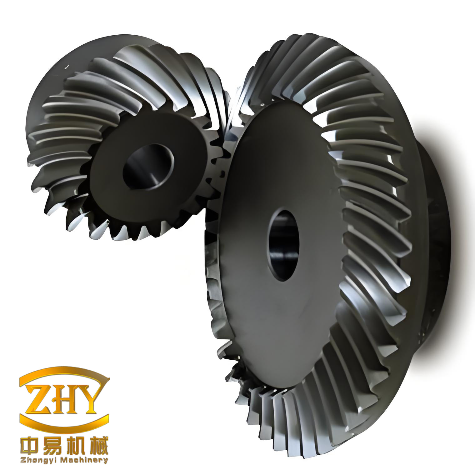
The proposed transmission differs from a conventional cylindrical worm and screw gear pair in one essential way. In a conventional pair, both flanks of the worm and both flanks of the screw gears are usually designed with identical or nearly identical lead and helix parameters. In the present design, the left and right flanks are deliberately given different leads and different thickness distributions. The media rack is also variable in lead and thickness. This variable media rack allows me to describe the meshing of the DIC worm and the screw gears as two simultaneous line-contact problems on a common auxiliary surface. When the media rack is removed, the DIC worm and the screw gears become point-contact conjugate surfaces. The contact point is the intersection of the two contact lines on the media rack. This geometric construction is the foundation of the entire analysis.
I organize the remainder of the article as follows. First, I define the design criteria of the variable-lead variable-thickness media rack worm drive. Second, I establish the coordinate systems and derive the tooth-surface equations of the media rack, the DIC worm, and the involute helical screw gears. Third, I develop the meshing equations, contact lines, contact points, contact ellipses, contact stress, and contact ratio. Fourth, I present the backlash adjustment principles for axial movement of the screw gears and axial movement of the DIC worm. Fifth, I report a numerical example, tooth contact analysis, and finite element simulation. Finally, I summarize the main conclusions.
Design Criteria
The proposed worm drive must satisfy a set of design criteria so that the media rack can be used consistently for both the DIC worm and the involute helical screw gears. I summarize these criteria in Table 1. The criteria ensure that the normal module is common, the axial and transverse modules are compatible, the two flanks have different leads, and the helix angles of the screw gears are complementary to the corresponding lead angles of the worm.
| Criterion | Description |
|---|---|
| Normal module | The DIC worm and the involute helical screw gears share the same normal module \(m_n\). |
| Axial and transverse modules | The two flanks of the DIC worm have different axial modules \(m_t\), and the two flanks of the screw gears have different transverse modules \(m_t\). |
| Lead angles | The left and right lead angles of the DIC worm, \(\gamma_L\) and \(\gamma_R\), are different. Therefore, the leads \(p_L\) and \(p_R\) are also different. This is why the worm is called a double-lead worm. |
| Helix angles | The left and right helix angles of the screw gears, \(\beta_L\) and \(\beta_R\), are different. They are complementary to the corresponding lead angles of the DIC worm. |
| Rotation direction | The rotation of the DIC worm and the rotation of the screw gears are in the same direction. |
Because the two flanks are geometrically asymmetric, I analyze the left flank first. The right flank follows by symmetry and by replacing the left-flank parameters with the right-flank parameters. The asymmetry is the key to backlash adjustment. If the two flanks were identical, axial displacement of the worm or the screw gears would not produce a controlled change in backlash. In the proposed design, the difference between the left and right leads and the difference between the left and right helix angles create a well-defined relationship between axial displacement and backlash variation.
The media rack is a variable-lead and variable-thickness rack. It is not a physical component in the final transmission. Instead, it is an auxiliary geometric tool. The media rack allows me to decompose the spatial meshing problem into two planar or quasi-planar meshing problems. The first problem is the meshing between the DIC worm and the media rack. The second problem is the meshing between the media rack and the screw gears. The two problems are connected by the common media rack. When the media rack is removed, the DIC worm and the screw gears form a conjugate pair with point contact. The contact point is the intersection of the two contact lines on the media rack. This decomposition greatly simplifies the mathematical treatment and provides a clear physical interpretation of the meshing process.
Coordinate Systems and Media Rack Geometry
I introduce fixed and moving coordinate systems for the DIC worm, the screw gears, and the media rack. The fixed coordinate systems are denoted by \(\sigma_m\), \(\sigma_n\), and \(\sigma_p\) for the DIC worm, the involute helical screw gears, and the media rack, respectively. The moving coordinate systems rigidly connected to the DIC worm, the screw gears, and the media rack are denoted by \(\sigma_1\), \(\sigma_2\), and \(\sigma_3\), respectively. The angular velocities of the DIC worm and the screw gears are \(\omega_1\) and \(\omega_2\). The media rack moves along the axial direction \(z_p\) with a linear velocity \(v_3\). The rotation angles are \(\phi_1\) and \(\phi_2\), and the media rack displacement is \(l\). The center distance of the worm drive is \(a\), and the meshing distance of the rack and gear is \(b\). These definitions are collected in Table 2.
| Symbol | Meaning |
|---|---|
| \(\sigma_m,\sigma_n,\sigma_p\) | Fixed coordinate systems of the DIC worm, screw gears, and media rack. |
| \(\sigma_1,\sigma_2,\sigma_3\) | Moving coordinate systems rigidly connected to the DIC worm, screw gears, and media rack. |
| \(\omega_1,\omega_2\) | Angular velocities of the DIC worm and the screw gears. |
| \(v_3\) | Linear velocity of the media rack along \(z_p\). |
| \(\phi_1,\phi_2\) | Rotation angles of the DIC worm and the screw gears. |
| \(l\) | Displacement of the media rack. |
| \(a\) | Center distance of the worm drive. |
| \(b\) | Meshing distance of the rack and gear. |
| \(i_{12}\) | Transmission ratio, \(i_{12}=\phi_1/\phi_2\). |
The media rack has two flanks with different inclination angles and different leads. Let \(\beta_L\) and \(\beta_R\) be the inclination angles of the left and right flanks. Let \(p_L\) and \(p_R\) be the corresponding leads. Let \(s_L\) and \(s_R\) be the thickness parameters. Let \(\alpha_{tL}\) and \(\alpha_{tR}\) be the transverse pressure angles. According to gear meshing theory, the transverse pressure angles and the leads satisfy
$$
\alpha_{tR}=\arctan\left(\frac{\tan\alpha_n}{\cos\beta_R}\right),\qquad
\alpha_{tL}=\arctan\left(\frac{\tan\alpha_n}{\cos\beta_L}\right),
$$
$$
p_R=\frac{\pi m_n}{\cos\beta_R},\qquad
p_L=\frac{\pi m_n}{\cos\beta_L}.
$$
Here \(m_n\) is the normal module and \(\alpha_n\) is the normal pressure angle. The left flank of the media rack is described in the auxiliary coordinate system \(\sigma_5\), while the right flank is described in \(\sigma_5’\). The tooth-surface equation and the unit normal vector of the left flank in \(\sigma_5\) are
$$
\mathbf{r}_{5L}(u_L,v_L)=
\begin{bmatrix}
u_L\\
v_L\\
0
\end{bmatrix},
\qquad
\mathbf{n}_{5L}=
\begin{bmatrix}
0\\
0\\
1
\end{bmatrix},
$$
where \(u_L\) and \(v_L\) are the surface parameters of the left flank. Similarly, the right flank is given by
$$
\mathbf{r}_{5R}(u_R,v_R)=
\begin{bmatrix}
u_R\\
v_R\\
0
\end{bmatrix},
\qquad
\mathbf{n}_{5R}=
\begin{bmatrix}
0\\
0\\
1
\end{bmatrix},
$$
where \(u_R\) and \(v_R\) are the right-flank parameters. The variable thickness of the media rack arises from the different leads on the two flanks. This variable thickness is the geometric origin of the adjustable backlash in the final worm drive. The media rack is therefore not merely a mathematical convenience; it is the carrier of the asymmetry that makes the transmission tunable.
DIC Worm Tooth Surface
The DIC worm is essentially a combination of two involute cylindrical worms with different leads. Its tooth surface is an involute helicoid. The left tooth surface in the moving coordinate system \(\sigma_1\) can be written as
$$
\mathbf{r}_{1L}(\lambda_w,\theta_w)=
\begin{bmatrix}
r_{b1}\cos(\delta_L+\theta_w-\lambda_w)-r_{b1}\lambda_w\sin(\delta_L+\theta_w-\lambda_w)\\
r_{b1}\sin(\delta_L+\theta_w-\lambda_w)+r_{b1}\lambda_w\cos(\delta_L+\theta_w-\lambda_w)\\
p_L\theta_w
\end{bmatrix},
$$
where \(r_{b1}\) is the base radius of the left flank, \(\lambda_w\) and \(\theta_w\) are the surface parameters, \(\delta_L\) is the thickness parameter on the base circle, and \(p_L\) is the lead of the left flank. Similarly, the right tooth surface is
$$
\mathbf{r}_{1R}(\lambda_w,\theta_w)=
\begin{bmatrix}
r_{b2}\cos(\delta_R+\theta_w-\lambda_w)-r_{b2}\lambda_w\sin(\delta_R+\theta_w-\lambda_w)\\
-r_{b2}\sin(\delta_R+\theta_w-\lambda_w)-r_{b2}\lambda_w\cos(\delta_R+\theta_w-\lambda_w)\\
p_R\theta_w
\end{bmatrix},
$$
where \(r_{b2}\) is the base radius of the right flank, \(\delta_R\) is the corresponding thickness parameter, and \(p_R\) is the lead of the right flank. The two base radii and the two leads are generally different. This difference is intentional. It allows the worm to engage the screw gears in a manner that can be adjusted axially. The involute helicoid of the DIC worm is shown schematically in the geometric construction, and the two flanks form a double-lead surface.
Because the worm is a double-lead worm, its tooth thickness varies linearly along the axial direction. This property is important for backlash adjustment. If the worm is moved axially, the effective tooth thickness at the meshing position changes. The same is true for the screw gears. When both the worm and the screw gears have variable thickness, the backlash can be controlled by moving either component. I will derive the exact relationships later. At this stage, it is sufficient to note that the DIC worm is not a standard worm. It is a worm whose two flanks are deliberately mismatched in lead, and this mismatch is the source of the adjustable backlash.
Involute Helical Screw Gears
The mating component is an involute helical gear. Because an involute helical gear can be regarded as a screw gear, I will often refer to it as a screw gear in the following analysis. The screw gears have two different helix angles on their two flanks. The left tooth surface in the moving coordinate system \(\sigma_2\) is
$$
\mathbf{r}_{2L}(\lambda_g,\theta_g)=
\begin{bmatrix}
r_{b3}\cos(\delta_L+\theta_g-\lambda_g)-r_{b3}\lambda_g\sin(\delta_L+\theta_g-\lambda_g)\\
r_{b3}\sin(\delta_L+\theta_g-\lambda_g)+r_{b3}\lambda_g\cos(\delta_L+\theta_g-\lambda_g)\\
r_{b3}\theta_g/(\cos\alpha_n\tan\beta_L)
\end{bmatrix},
$$
where \(r_{b3}\) is the base radius of the left flank, \(\lambda_g\) and \(\theta_g\) are the surface parameters, \(\delta_L\) is the thickness parameter on the base circle, and \(\beta_L\) is the left helix angle. The right tooth surface is
$$
\mathbf{r}_{2R}(\lambda_g,\theta_g)=
\begin{bmatrix}
r_{b4}\cos(\delta_R+\theta_g-\lambda_g)-r_{b4}\lambda_g\sin(\delta_R+\theta_g-\lambda_g)\\
-r_{b4}\sin(\delta_R+\theta_g-\lambda_g)-r_{b4}\lambda_g\cos(\delta_R+\theta_g-\lambda_g)\\
r_{b4}\theta_g/(\cos\alpha_n\tan\beta_R)
\end{bmatrix},
$$
where \(r_{b4}\) is the base radius of the right flank, \(\delta_R\) is the corresponding thickness parameter, and \(\beta_R\) is the right helix angle. The two helix angles are different. This difference is the counterpart of the difference between the two leads of the DIC worm. The screw gears therefore have a left flank and a right flank that are not mirror images in the usual sense. They are asymmetric in helix angle and thickness distribution.
The screw gears and the DIC worm are conjugate through the media rack. The media rack bridges the two surfaces. The left flank of the screw gears meshes with the left flank of the media rack, and the right flank of the screw gears meshes with the right flank of the media rack. At the same time, the left and right flanks of the DIC worm mesh with the corresponding flanks of the media rack. The media rack therefore carries two contact lines: one for the worm and one for the screw gears. The intersection of these two contact lines is the instantaneous contact point of the worm drive. This construction is valid because the media rack is a common tangent surface to both the worm and the screw gears at the meshing position.
Meshing Analysis
I now derive the meshing equations for the media rack with the DIC worm and with the screw gears. The relative velocity between the DIC worm and the media rack in the auxiliary coordinate system \(\sigma_5\) is
$$
\mathbf{v}_{15L}=
\begin{bmatrix}
v_{15x}\\
v_{15y}\\
v_{15z}
\end{bmatrix}
=
\begin{bmatrix}
\omega_1 b\cos\beta_L-\omega_1 a\cos\beta_L-v_3\cos\alpha_n\cos\beta_L+\omega_1 v_L\cos\alpha_n\cos\beta_L\\
v_3\sin\alpha_n-\omega_1 u_L\cos\alpha_n\cos\beta_L\\
\omega_1 a\sin\beta_L-\omega_1 b\sin\beta_L-v_3\cos\alpha_n\cos\beta_L-\omega_1 u_L\sin\alpha_n-\omega_1 v_L\cos\alpha_n\sin\beta_L
\end{bmatrix}.
$$
The meshing equation between the DIC worm and the media rack is
$$
\Phi_{1L}(u_L,v_L)=
\omega_1 a\sin\beta_L-\omega_1 b\sin\beta_L
-\frac{\omega_1}{i_{12}}b\cos\alpha_n\cos\beta_L
-\omega_1 u_L\sin\alpha_n
-\omega_1 v_L\cos\alpha_n\sin\beta_L.
$$
Using the media rack surface equation and this meshing equation, the contact line \(L_1\) between the DIC worm and the media rack is obtained as
$$
\mathbf{r}_{15L}(u_L,v_L)=
\begin{bmatrix}
r_{15x}\\
r_{15y}\\
r_{15z}
\end{bmatrix}
=
\begin{bmatrix}
\frac{1}{\sin\alpha_n}\left(v_3\cos\alpha_n\sin\beta_L+a\sin\beta_L-b\sin\beta_L+\frac{1}{i_{12}}b\cos\alpha_n\cos\beta_L\right)\\
v_L\\
0
\end{bmatrix}.
$$
Similarly, the relative velocity between the screw gears and the media rack in \(\sigma_5\) is
$$
\mathbf{v}_{25L}=
\begin{bmatrix}
v_{25x}\\
v_{25y}\\
v_{25z}
\end{bmatrix}
=
\begin{bmatrix}
\sin\beta_L(\omega_2 v_L-\omega_2 l\sin\alpha_n-v_3\cos\alpha_n+\omega_2 b\cos\alpha_n)\\
\omega_2 b\sin\alpha_n-\omega_2 l\cos\alpha_n\cos\beta_L+v_3\sin\alpha_n-\omega_2 u_L\sin\beta_L\\
\cos\beta_L(\omega_2 v_L-\omega_2 l\sin\alpha_n-v_3\cos\alpha_n+\omega_2 b\cos\alpha_n)
\end{bmatrix}.
$$
The meshing equation between the screw gears and the media rack is
$$
\Phi_{2L}(u_L,v_L)=
\cos\beta_L\left(\omega_2 v_L-\omega_2 l\sin\alpha_n-v_3\cos\alpha_n+\omega_2 b\cos\alpha_n\right).
$$
The contact line \(L_2\) between the screw gears and the media rack is
$$
\mathbf{r}_{25L}(u_L,\phi_1)=
\begin{bmatrix}
r_{25x}\\
r_{25y}\\
r_{25z}
\end{bmatrix}
=
\begin{bmatrix}
u_L\\
\frac{\phi_1}{i_{12}}b\sin\alpha_n\\
0
\end{bmatrix}.
$$
The instantaneous contact point of the worm drive is the intersection of \(L_1\) and \(L_2\). I set
$$
\mathbf{r}_{15L}(u_L,v_L)=\mathbf{r}_{25L}(u_L,\phi_1).
$$
The contact point in \(\sigma_5\) is then
$$
\mathbf{r}_{5p}(\phi_2)=
\begin{bmatrix}
r_{5x}\\
r_{5y}\\
r_{5z}
\end{bmatrix}
=
\begin{bmatrix}
\frac{1}{\sin\alpha_n}\left(\phi_2 b\sin\alpha_n\cos\alpha_n\sin\beta_L+a\sin\beta_L-b\sin\beta_L+\frac{1}{i_{12}}b\cos\alpha_n\cos\beta_L\right)\\
\phi_2 b\sin\alpha_n\\
0
\end{bmatrix}.
$$
The contact point in the moving coordinate system \(\sigma_2\) of the screw gears is obtained by the coordinate transformation
$$
\mathbf{r}_{2p}(\phi_2)=M_{25}\mathbf{r}_{5p},
$$
where \(M_{25}\) is the transformation matrix from the auxiliary coordinate system \(\sigma_5\) to the moving coordinate system \(\sigma_2\). This contact point moves across the tooth surface during meshing. Because the two flanks have different helix angles, the contact trajectories on the left and right flanks are different. This difference is used in the backlash adjustment strategy.
Contact Ellipse
Under load, the theoretical point contact becomes an elliptical contact area due to elastic deformation. Let \(\zeta\) and \(\eta\) be the geometric parameters of the contact ellipse. According to gear geometry theory, the instantaneous contact ellipse in \(\sigma_5\) can be expressed as
$$
A\zeta^2+B\eta^2=\pm\delta,
$$
where
$$
A=\frac{1}{4}\left[
(k_{wI}+k_{wII})-(k_{gI}+k_{gII})
-\sqrt{(k_{wI}-k_{wII})^2-2(k_{wI}-k_{wII})(k_{gI}-k_{gII})\cos\theta_{gw}+(k_{gI}-k_{gII})^2}
\right],
$$
$$
B=\frac{1}{4}\left[
(k_{wI}+k_{wII})-(k_{gI}+k_{gII})
+\sqrt{(k_{wI}-k_{wII})^2-2(k_{wI}-k_{wII})(k_{gI}-k_{gII})\cos\theta_{gw}+(k_{gI}-k_{gII})^2}
\right].
$$
Here \(k_{gI}\) and \(k_{gII}\) are the principal curvatures of the left flank of the screw gears, and \(k_{wI}\) and \(k_{wII}\) are the principal curvatures of the left flank of the DIC worm. For the present geometry, \(k_{gII}=0\) and \(k_{wII}=0\). The angle \(\theta_{gw}\) is the angle between the principal directions. The quantity \(\delta\) represents the elastic deformation of the tooth-surface material.
The maximum contact stress \(q_{\max}\) between the conjugate surfaces is
$$
q_{\max}=
\frac{\lambda_a\lambda_b}{\pi}
\sqrt{
\frac{3P(A+B)}
{2\left((1-\mu_1^2)/E_1+(1-\mu_2^2)/E_2\right)^2}
},
$$
where \(P\) is the normal force between the conjugate tooth surfaces, \(\mu_1\) and \(\mu_2\) are the Poisson ratios of the worm and screw gear materials, \(E_1\) and \(E_2\) are the corresponding elastic moduli, and \(\lambda_a\) and \(\lambda_b\) are the length coefficients of the contact ellipse axes. This expression is used later in the finite element verification.
Contact Ratio
Because the two flanks have different helix angles, the contact trajectories are different. Let \(P_{\mathrm{in}}\) be the beginning point of meshing on the media rack tooth surface and \(P_{\mathrm{out}}\) be the end point. The contact ratio is
$$
\varepsilon=\frac{z_1|\phi_{1\mathrm{in}}-\phi_{1\mathrm{out}}|}{2\pi},
$$
where \(\phi_{1\mathrm{in}}\) and \(\phi_{1\mathrm{out}}\) are the DIC worm rotation angles corresponding to \(P_{\mathrm{in}}\) and \(P_{\mathrm{out}}\). These angles satisfy
$$
r_{5x}(\phi_{1\mathrm{in}})^2+\left(\frac{\phi_{1\mathrm{in}}r_{5y}}{i_{12}\phi_2}\right)^2=r_{a2}^2,
$$
$$
r_{5x}(\phi_{1\mathrm{out}})^2+\left(\frac{\phi_{1\mathrm{out}}r_{5y}}{i_{12}\phi_2}\right)^2=(a-r_{a1})^2,
$$
where \(r_{a1}\) and \(r_{a2}\) are the addendum radii of the DIC worm and the screw gears. The contact ratio is an important indicator of load-sharing capability. In the proposed drive, the contact ratio can be adjusted by changing the axial position of the worm or the screw gears, but the contact pattern remains consistent with the theoretical prediction.
Backlash Adjustment
The adjustable backlash is one of the main advantages of the proposed worm drive. I consider two methods. In the first method, the involute helical screw gears are moved axially. In the second method, the DIC worm is moved axially. Both methods change the effective tooth thickness at the meshing position and therefore change the backlash.
Axial Movement of the Screw Gears
The screw gears have a variable tooth thickness along their axial direction. This property follows from the involute helicoid geometry. If the tooth surface \(\Sigma_2\) is rotated by an angle \(\zeta_1\) about the screw gear axis \(z_2\), a new surface \(\Sigma_3\) is obtained:
$$
\mathbf{r}_{3L}(\lambda_g,\theta_g)=
\begin{bmatrix}
r_{b3}\cos(\delta_L+\theta_g-\lambda_g-\zeta_1)-r_{b3}\lambda_g\sin(\delta_L+\theta_g-\lambda_g-\zeta_1)\\
r_{b3}\sin(\delta_L+\theta_g-\lambda_g-\zeta_1)+r_{b3}\lambda_g\cos(\delta_L+\theta_g-\lambda_g-\zeta_1)\\
r_{b3}(\theta_g-\zeta_1)/(\cos\alpha_n\tan\beta_L)
\end{bmatrix}.
$$
If the same surface is translated along its axial direction \(z_2\) by a distance \(h_1\), a new surface \(\Sigma_4\) is obtained:
$$
\mathbf{r}_{4L}(\lambda_g,\theta_g)=
\begin{bmatrix}
r_{b3}\cos(\delta_L+\theta_g-\lambda_g)-r_{b3}\lambda_g\sin(\delta_L+\theta_g-\lambda_g)\\
r_{b3}\sin(\delta_L+\theta_g-\lambda_g)+r_{b3}\lambda_g\cos(\delta_L+\theta_g-\lambda_g)\\
r_{b3}\theta_g/(\cos\alpha_n\tan\beta_L)-h_1
\end{bmatrix}.
$$
Comparing \(\Sigma_3\) and \(\Sigma_4\), when
$$
h_1=\frac{r_{b3}\zeta_1}{\cos\alpha_n\tan\beta_L},\qquad
\delta_2=\delta_1-\zeta_1,
$$
the two surfaces coincide:
$$
\mathbf{r}_{3L}(\lambda_g,\theta_g)-\mathbf{r}_{4L}(\lambda_g,\theta_g)=0.
$$
Therefore, the helical motion of the screw gear tooth surface is equivalent to an axial translation. The backlash change \(\Delta\delta_g\) caused by an axial displacement \(h_1\) of the screw gears is
$$
\Delta\delta_g=h_1\cos\alpha_n|\tan\beta_L-\tan\beta_R|.
$$
This equation shows that the backlash is proportional to the axial displacement and to the difference between the tangents of the two helix angles. If the two helix angles were equal, the backlash would not change with axial displacement. The asymmetry of the screw gears is therefore essential.
Axial Movement of the DIC Worm
The DIC worm also has a variable tooth thickness along its axial direction because its two flanks have different leads. If the tooth surface \(\Sigma_1\) is rotated by an angle \(\zeta_2\) about the worm axis \(z_1\), a new surface \(\Sigma_5\) is obtained:
$$
\mathbf{r}_{5L}(\lambda_w,\theta_w)=
\begin{bmatrix}
r_{b1}\cos(\delta_3+\theta_w-\lambda_w-\zeta_2)-r_{b1}\lambda_w\sin(\delta_3+\theta_w-\lambda_w-\zeta_2)\\
r_{b1}\sin(\delta_3+\theta_w-\lambda_w-\zeta_2)+r_{b1}\lambda_w\cos(\delta_3+\theta_w-\lambda_w-\zeta_2)\\
\frac{p_L}{2\pi}(\theta_w-\zeta_2)
\end{bmatrix}.
$$
If the same surface is translated along the worm axis \(z_1\) by a distance \(h_2\), a new surface \(\Sigma_6\) is obtained:
$$
\mathbf{r}_{6L}(\lambda_w,\theta_w)=
\begin{bmatrix}
r_{b1}\cos(\delta_4+\theta_w-\lambda_w)-r_{b1}\lambda_w\sin(\delta_4+\theta_w-\lambda_w)\\
r_{b1}\sin(\delta_4+\theta_w-\lambda_w)+r_{b1}\lambda_w\cos(\delta_4+\theta_w-\lambda_w)\\
\frac{p_L}{2\pi}\theta_w-h_2
\end{bmatrix}.
$$
Comparing \(\Sigma_5\) and \(\Sigma_6\), when
$$
h_2=\frac{p_L\zeta_2}{2\pi},\qquad
\delta_4=\delta_3-\zeta_2,
$$
the two surfaces coincide:
$$
\mathbf{r}_{5L}(\lambda_w,\theta_w)-\mathbf{r}_{6L}(\lambda_w,\theta_w)=0.
$$
Thus, the helical motion of the DIC worm tooth surface is equivalent to an axial translation. The backlash change \(\Delta\delta_g\) caused by an axial displacement \(h_2\) of the DIC worm is
$$
\Delta\delta_g=2h_2\left|\frac{p_L-p_R}{p_L+p_R}\right|.
$$
Again, the backlash change is proportional to the axial displacement and to the difference between the two leads. If the two leads were equal, the backlash would not change. The double-lead design of the worm is therefore essential for the second adjustment method. Table 3 summarizes the two adjustment methods and their governing equations.
| Adjustment method | Displacement | Backlash change |
|---|---|---|
| Axial movement of screw gears | \(h_1\) | \(\Delta\delta_g=h_1\cos\alpha_n|\tan\beta_L-\tan\beta_R|\) |
| Axial movement of DIC worm | \(h_2\) | \(\Delta\delta_g=2h_2\left|\frac{p_L-p_R}{p_L+p_R}\right|\) |
These two relationships give the designer two independent ways to control backlash. The first method moves the screw gears, while the second method moves the worm. In practice, one method may be preferred depending on the available space and the machine architecture. The important point is that both methods are based on the same variable-lead and variable-thickness media rack concept. The media rack provides a unified explanation of both adjustment mechanisms.
Numerical Example and Tooth Contact Analysis
I now present a numerical example to demonstrate the proposed design and to verify the meshing and backlash adjustment theories. The design parameters are listed in Table 4. The DIC worm has one thread, and the screw gears have fifty teeth. The normal module is \(4\,\mathrm{mm}\). The left helix angle of the screw gears is \(12.574^\circ\), and the right helix angle is \(12.597^\circ\). The corresponding leads of the worm are \(12.574\,\mathrm{mm}\) and \(12.597\,\mathrm{mm}\). The bottom clearance coefficient is \(0.2\), and the addendum coefficient is \(1\). Both the worm and the screw gears are right-handed.
| Parameter | DIC worm | Screw gears |
|---|---|---|
| Center distance (mm) | 125 | — |
| Normal pressure angle \(\alpha_n\) (deg) | 20 | 20 |
| Number of threads / teeth | 1 | 50 |
| Normal module \(m_n\) (mm) | 4 | 4 |
| Left helix angle \(\beta_L\) (deg) | — | 12.574 |
| Right helix angle \(\beta_R\) (deg) | — | 12.597 |
| Left lead \(p_L\) (mm) | 12.574 | — |
| Right lead \(p_R\) (mm) | 12.597 | — |
| Bottom clearance coefficient \(c^*\) | 0.2 | 0.2 |
| Addendum coefficient \(h^*\) | 1 | 1 |
| Handedness | Right | Right |
Using the contact point equation and the contact ellipse equation, I perform tooth contact analysis on the screw gear tooth surface. In the normal meshing condition, two pairs of conjugate surfaces participate in meshing simultaneously. Their contact points are denoted as \(a\) and \(b\). During a single tooth meshing cycle, the contact point moves from the beginning of meshing to the end of meshing. The size of the contact ellipse changes because the principal curvatures vary along the contact path. When the screw gears are translated axially by \(1\,\mathrm{mm}\), the meshing process shifts, but the contact trajectory remains consistent with the theoretical prediction. When the screw gears are translated axially by \(2\,\mathrm{mm}\) and simultaneously rotated by \(0.02^\circ\), the same effect is achieved. The contact ellipses after adjustment are the same size as those in the initial meshing condition. This result verifies that the backlash adjustment does not degrade the contact characteristics.
The tooth contact analysis confirms that both the axial translation and the helical motion of the screw gears can be used to adjust backlash. The two methods produce the same contact pattern because the helical motion of an involute helicoid is equivalent to an axial translation. This equivalence is a direct consequence of the geometric properties of the screw gears. The same equivalence holds for the DIC worm. Therefore, the proposed adjustable-backlash worm drive can be tuned without changing the fundamental meshing performance.
Finite Element Simulation
To further validate the theoretical results, I build a three-dimensional model of the proposed worm drive and perform finite element analysis. The DIC worm is made of 42CrMoA with a Poisson ratio of 0.28 and a Young’s modulus of \(2.12\times 10^{11}\,\mathrm{Pa}\). The involute helical screw gears are made of 17CrNiMo6 with a Poisson ratio of 0.27 and a Young’s modulus of \(2.35\times 10^{11}\,\mathrm{Pa}\). A rigid surface is used to fix the DIC worm, and another rigid surface is used to constrain the screw gears. The screw gears are allowed one tangential degree of freedom about the \(z_2\) axis. A torque of \(100\,\mathrm{N\cdot m}\) is applied to the screw gears. Three cases are considered: initial meshing, axial movement of the screw gears by \(1\,\mathrm{mm}\), and axial movement of the screw gears by \(2\,\mathrm{mm}\).
The finite element results are summarized in Table 5. In the initial meshing condition, the maximum contact stress on the left flank is \(311.23\,\mathrm{MPa}\), and the maximum contact stress on the right flank is \(339.35\,\mathrm{MPa}\). These values are very close to the theoretical predictions from the contact stress equation. After axial movement of the screw gears by \(1\,\mathrm{mm}\), the contact stresses remain essentially the same. After axial movement by \(2\,\mathrm{mm}\), the contact stresses again remain essentially the same. The contact state changes in the same way as predicted by the tooth contact analysis. The right flank has a slightly higher maximum contact stress than the left flank because of its larger helix angle. This difference is also captured by the theoretical model.
| Case | Left flank maximum stress (MPa) | Right flank maximum stress (MPa) |
|---|---|---|
| Initial meshing | 311.23 | 339.35 |
| Screw gears moved 1 mm | 311.23 | 339.35 |
| Screw gears moved 2 mm | 311.23 | 339.35 |
The finite element simulation also shows that the DIC worm and the screw gears are in point contact during meshing. The contact area is small and elliptical, as predicted by the contact ellipse model. When the backlash is adjusted, the contact area does not change significantly. This means that the adjustment can be performed without compromising the load-carrying capacity of the transmission. The contact stress is mainly determined by the normal force, the principal curvatures, and the material properties. Since these quantities do not change significantly with axial displacement, the maximum contact stress remains nearly constant. This is a desirable feature for practical applications.
I also compare the contact stress results for the case in which two pairs of teeth mesh simultaneously and the case in which one pair of teeth meshes. The trends are consistent. The right flank carries a slightly higher stress because its helix angle is larger. The theoretical values from the contact stress equation are in good agreement with the finite element results. This agreement validates the mathematical model and the media rack approach. The screw gears, the DIC worm, and the media rack form a consistent geometric system that can be used for design and analysis.
Discussion
The proposed variable-lead variable-thickness media rack worm drive has several advantages. First, it provides a clear geometric interpretation of a complex spatial meshing problem. The media rack acts as a bridge between the DIC worm and the screw gears. Second, it enables adjustable backlash without changing the basic contact pattern. Third, it allows two independent adjustment methods: axial movement of the screw gears and axial movement of the DIC worm. Fourth, the design criteria are straightforward and can be implemented in a standard gear design environment. Fifth, the contact stress and contact ellipse can be predicted analytically and verified by finite element analysis.
The key role of screw gears in this transmission cannot be overstated. The involute helical gear is a screw gear, and its two flanks have different helix angles. This asymmetry is what makes the backlash adjustable. If the screw gears had identical helix angles on both flanks, the axial displacement would not produce a controlled backlash change. The same is true for the DIC worm: if the two leads were identical, the axial displacement of the worm would not change the backlash. The double-lead worm and the asymmetric screw gears are therefore complementary. They form a matched pair that can be tuned to meet different backlash requirements.
In practice, the designer can choose the adjustment method based on the application. If the screw gears are more accessible, the first method may be preferred. If the worm is more accessible, the second method may be preferred. The two methods can also be combined. For example, a coarse adjustment can be made by moving the worm, and a fine adjustment can be made by moving the screw gears. The relationships derived in this work give the exact amount of axial displacement required for a desired backlash change. This makes the design process predictable and repeatable.
There are also limitations. The proposed design requires a double-lead worm and asymmetric screw gears. These components are more complex to manufacture than standard worm drive components. However, modern CNC machining and grinding technologies can produce variable-lead and variable-thickness surfaces with high accuracy. The media rack concept can be used to generate the tool paths for both the worm and the screw gears. Therefore, the manufacturing complexity is manageable. The benefits of adjustable backlash and stable contact performance are likely to outweigh the additional manufacturing cost in many applications.
Another limitation is that the analysis presented here focuses on the left flank. The right flank can be analyzed in the same way by replacing the left-flank parameters with the right-flank parameters. The symmetry of the formulation ensures that the right-flank results can be obtained without repeating the entire derivation. In the numerical example, the right-flank contact stress is slightly higher than the left-flank contact stress. This difference is due to the larger helix angle on the right flank. The designer can account for this difference by adjusting the tooth thickness or the material properties if necessary.
Future work can extend the proposed method to dynamic analysis. The current study focuses on quasi-static meshing and contact stress. In a real transmission, the dynamic behavior, including vibration and noise, is also important. The adjustable backlash may affect the dynamic characteristics. A dynamic model based on the media rack concept could be developed to study these effects. In addition, thermal effects and lubrication can be included in the contact stress analysis. The variable-lead and variable-thickness geometry may influence the oil film formation and the heat generation. These topics are beyond the scope of the present work but are natural extensions of the proposed framework.
Conclusion
I have proposed a variable-lead variable-thickness media rack worm drive with screw gears. The main conclusions are as follows.
1. A new adjustable-backlash worm drive composed of a double-lead involute cylindrical worm and involute helical screw gears has been proposed. The design criteria have been established. The two flanks of the worm have different leads, and the two flanks of the screw gears have different helix angles. The normal module is common to both components.
2. A mathematical model and geometric principle have been established for the proposed worm drive. The variable-lead and variable-thickness media rack has been introduced as an auxiliary surface. The media rack bridges the DIC worm and the screw gears and allows the meshing problem to be decomposed into two line-contact problems. The contact point of the worm drive is the intersection of the two contact lines on the media rack.
3. The meshing performance has been analyzed. The contact lines, contact points, contact ellipses, contact stress, and contact ratio have been derived. The contact ellipse and maximum contact stress equations provide analytical tools for design evaluation. The tooth contact analysis confirms that the contact trajectory and contact ellipse size remain consistent after backlash adjustment.
4. Two backlash adjustment methods have been proposed. The first method moves the screw gears axially, and the second method moves the DIC worm axially. The backlash change is proportional to the axial displacement and to the difference between the two leads or the two helix angles. The exact relationships have been derived and verified.
5. Finite element simulation has been performed to validate the theoretical results. The maximum contact stresses on the left and right flanks are in good agreement with the analytical predictions. The contact stress does not change significantly after backlash adjustment. This confirms that the adjustable backlash does not degrade the meshing performance.
6. The proposed design provides a practical way to compensate for manufacturing errors, assembly errors, and tooth-surface wear in worm drives. The screw gears and the double-lead worm form a matched pair that can be tuned to meet different backlash requirements. The media rack concept provides a unified framework for design, analysis, and verification.
In summary, the variable-lead variable-thickness media rack worm drive with screw gears offers a promising solution for applications that require precise backlash control and stable meshing performance. The combination of a double-lead worm and asymmetric screw gears creates a tunable transmission that can be analyzed with the methods presented in this work. The analytical equations, tables, and numerical results provide a solid foundation for further research and practical implementation.