
In my research, I focused on the assembly quality control and measurement technology of a hypoid bevel gear pair used in a four-wheel-drive power take-off unit. The hypoid bevel gear is widely used in automotive drivetrains because of its high load capacity, smooth transmission, and flexible spatial layout. However, the hypoid bevel gear has a complex tooth surface and operates under local conjugate meshing conditions. Therefore, the assembly precision of the hypoid bevel gear pair must be strictly controlled. I studied the geometric deviation detection before assembly, the contact zone position control during assembly, and the transmission quality inspection after assembly. The main objective was to reduce the defect rate in the power take-off assembly line and to provide a reliable method for quality evaluation of the hypoid bevel gear pair.
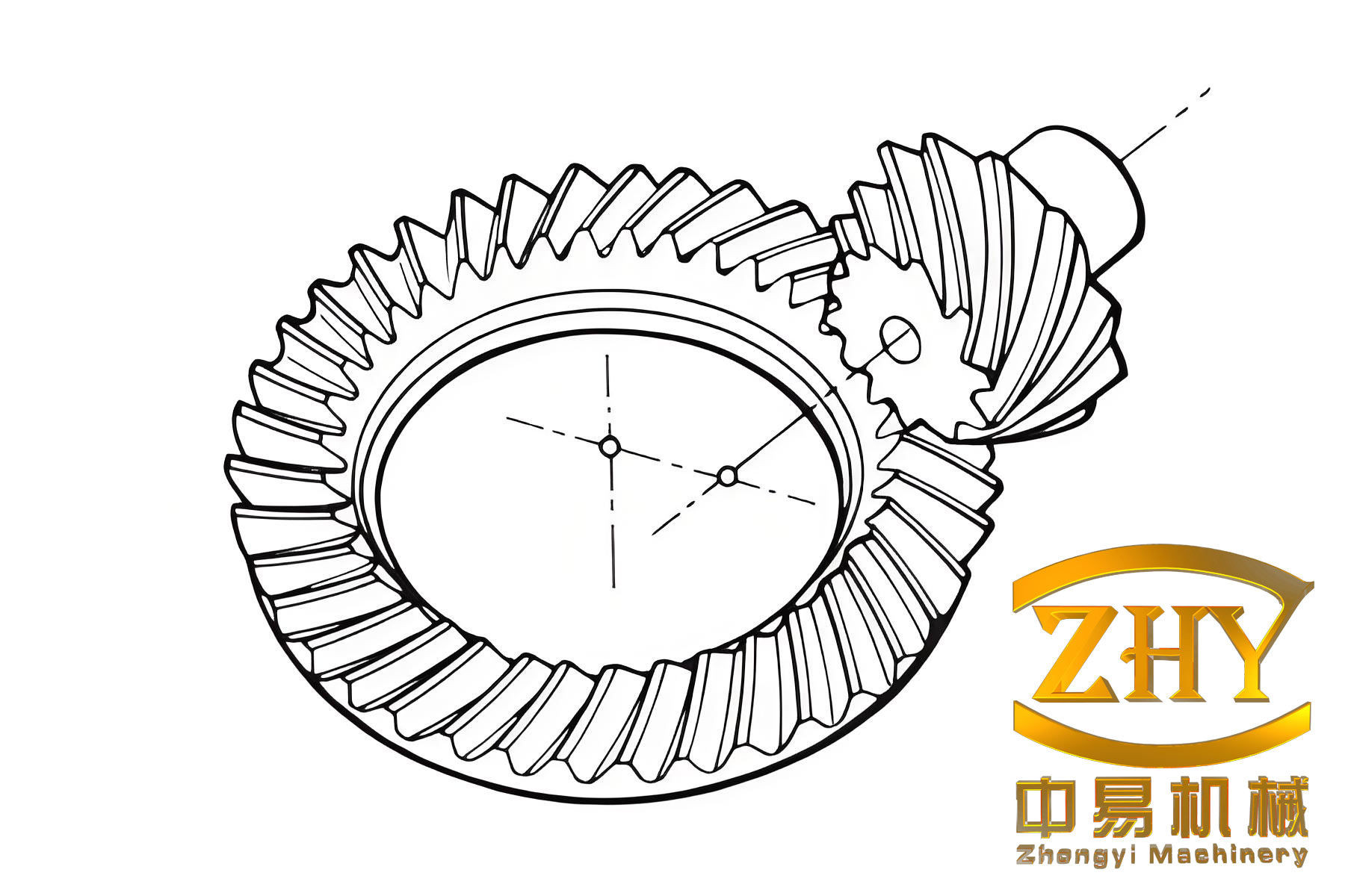
The hypoid bevel gear pair in my study is a Gleason-type spiral bevel gear with a tapered tooth depth. The pinion is smaller and easier to control during manufacturing, while the ring gear is assembled with a hollow shaft by interference fit and laser welding. The main parameters of the hypoid bevel gear pair are listed in Table 1. These parameters are essential for the kinematic simulation, the double-flank meshing test, and the circumference backlash measurement.
| Parameter | Pinion | Ring Gear |
|---|---|---|
| Number of teeth | 17 | 27 |
| Transverse module (mm) | 5.270 | 5.270 |
| Mean spiral angle | 47°06′ | 38°59′ |
| Spiral direction | Right hand | Left hand |
| Cutter diameter (mm) | 127 | 127 |
| Theoretical whole depth (mm) | 9.533 | 9.504 |
| Theoretical outer diameter (mm) | 111.435 | 146.25 |
| Pinion offset (mm) | 10 | 10 |
| Shaft angle | 90° | 90° |
From the actual production line, I classified the main causes of defective power take-off units. Five geometric deviations have the greatest influence on the meshing accuracy of the hypoid bevel gear pair: tooth profile deviation of the hypoid bevel gear, local tooth surface damage, foreign matter on the meshing surface, eccentricity of the ring gear shaft, and shaft angle error between the ring gear and its shaft. Each of these deviations can change the contact zone position and thus affect the transmission quality of the hypoid bevel gear. I developed a double-flank meshing detection method to identify these deviations before assembly and to calculate the axial shim compensation for the contact zone.
The principle of conjugate surfaces is the foundation of hypoid bevel gear meshing. For two surfaces \(S_1\) and \(S_2\) that maintain contact and satisfy a given motion law, the following equations must hold at the contact point \(M\):
$$
\begin{cases}
\mathbf{r}_2 = \mathbf{m} + \mathbf{r}_1 \\
\mathbf{n}_2 = \mathbf{n}_1 \\
\mathbf{n} \cdot \mathbf{v}_{12} = 0
\end{cases}
$$
Here, \(\mathbf{r}_1\) and \(\mathbf{r}_2\) are the radial vectors of the contact point on \(S_1\) and \(S_2\), \(\mathbf{n}_1\) and \(\mathbf{n}_2\) are the unit normal vectors, \(\mathbf{m} = \overrightarrow{O_2O_1}\), and \(\mathbf{v}_{12}\) is the relative velocity between the two surfaces. For a hypoid bevel gear pair, the tooth surfaces are not fully conjugate; they are modified to achieve local conjugate contact. The local conjugate condition allows the contact zone to be controlled by curvature corrections. The normal curvature and geodesic torsion of the tooth surface determine the contact ellipse. The approximate paraboloid equation for the tooth surface is:
$$
z = \frac{1}{2} K_x x^2 + G xy + \frac{1}{2} K_y y^2
$$
where \(K_x\) and \(K_y\) are the normal curvatures in two principal directions, and \(G\) is the geodesic torsion. By introducing curvature corrections, the length and width of the contact zone can be adjusted independently. In the manufacturing of the hypoid bevel gear, the ring gear is usually cut first, and the pinion is then generated to match the ring gear. The cutter head parameters and machine settings are calculated based on the ring gear tooth surface. The actual pinion tooth surface is close to the theoretical surface only in a local region around the reference point. Therefore, the hypoid bevel gear pair operates under local conjugate contact, and the contact zone position must be precisely controlled during assembly.
To detect the geometric deviations of the hypoid bevel gear pair, I used a double-flank meshing method. In a conventional double-flank test for cylindrical gears, the center distance variation is measured. For a hypoid bevel gear pair, there is no single center distance because the axes are offset and perpendicular. Instead, I fixed the distance from the pinion end face to the ring gear axis and measured the variation of the distance from the ring gear end face to the pinion axis. This variation is called the pinion runout. The pinion runout curve contains information about the geometric deviations of the hypoid bevel gear pair.
I modeled the hypoid bevel gear tooth surface mathematically. The spherical involute generation principle gives the tooth profile. For a point \(A\) on a circular plane rolling on a base cone, the trajectory in the moving coordinate system is:
$$
\begin{cases}
x_1 = R_b \sin\psi \\
y_1 = 0 \\
z_1 = R_b \cos\psi
\end{cases}
$$
where \(R_b\) is the radius of the circular plane, and \(\psi\) is the angle between the initial tangent and the \(z_1\) axis. Transforming this trajectory to the fixed coordinate system yields the spherical involute equation:
$$
\begin{cases}
x = R_b (\sin\varphi \sin\psi + \cos\varphi \cos\psi \cos\theta) \\
y = R_b (-\cos\varphi \sin\psi + \sin\varphi \cos\psi \sin\theta) \\
z = R_b \cos\psi \cos\theta
\end{cases}
$$
where \(\theta\) is the base cone angle and \(\varphi\) is the generating angle. Based on this equation, I built a 3D model of the hypoid bevel gear pair in SolidWorks. The model included the pinion, the ring gear, and the ring gear shaft. Because the actual hypoid bevel gear has micron-level accuracy, the 3D model was not accurate enough for direct quantitative analysis. However, I used the model to simulate the five geometric deviations with exaggerated magnitudes to study their effects on the pinion runout curve.
I imported the 3D model into Adams and performed kinematic simulations. The ring gear was fixed to its shaft, and the shaft was constrained to rotate about its axis. The pinion was allowed to rotate about its own axis and to translate along the direction perpendicular to the pinion axis. A spring force was applied to the pinion to maintain contact. A contact constraint was defined between the pinion and the ring gear. The ring gear was driven by a motion input. The pinion runout was recorded as the displacement of the pinion along the floating direction. The simulation results showed that the five geometric deviations produce distinct features in the pinion runout curve.
| Deviation type | Time-domain feature | Frequency-domain feature |
|---|---|---|
| Tooth profile deviation | Small periodic fluctuation | Energy at meshing frequency |
| Ring gear shaft eccentricity | Periodic fluctuation at ring gear shaft frequency | Increased amplitude at ring gear shaft frequency |
| Ring gear shaft angle error | Periodic fluctuation with larger amplitude | Increased amplitude at both shaft frequency and meshing frequency |
| Local tooth surface damage | Sharp spike and distortion | Energy leakage around meshing frequency |
| Foreign matter | Small bump on the curve | Slight change at meshing frequency |
Based on the simulation results, I designed a double-flank meshing test rig for the hypoid bevel gear. The test rig must satisfy the following conditions: the pinion can only translate along the floating direction and rotate about its own axis; the ring gear can only rotate about its own axis; the distance from the pinion end face to the ring gear axis is fixed; the shaft angle is 90°; and the offset distance is 10 mm. The test rig consists of a pinion clamping mechanism, a ring gear positioning mechanism, a contact zone position control mechanism, and a pressing force mechanism. The pinion is clamped by an expansion sleeve, which ensures high coaxiality and easy automation. The ring gear is supported by bearings and pressed by a pneumatic cylinder. The contact zone position is controlled by a servo motor and a linear guide. The pressing force is generated by a weight through a pulley system.
For data acquisition, I used two grating displacement sensors. One sensor monitors the distance from the pinion end face to the ring gear axis, and the other monitors the distance from the ring gear end face to the pinion axis. The resolution of the sensors is 0.1 μm. The signals are acquired by an NI DAQ-9181 chassis with a 9411 module. The sampling frequency is 25 kHz. The data are transferred to a host computer via TCP/IP. The PLC controls the sequence of the servo motor and pneumatic cylinders.
I conducted experiments to optimize the test parameters. The pressing force, rotational speed, lubrication condition, and non-integer cycle sampling were studied. The results are summarized in Table 2. A pressing force of 5 kg, a rotational speed of 120 r/min, and oil lubrication gave the best repeatability and stability. Under these conditions, the pinion runout curve was smooth and the geometric deviations could be clearly identified.
| Parameter | Range tested | Optimal value | Effect on runout |
|---|---|---|---|
| Pressing force | 3, 4, 5, 6, 8 kg | 5 kg | Lower force causes drift; higher force causes seizure |
| Rotational speed | 30, 60, 90, 120, 150, 180 r/min | 120 r/min | Higher speed reduces detail capture; lower speed increases noise |
| Lubrication | Dry, oil, grease | Oil | Oil improves repeatability; grease is less efficient |
| Sampling cycle | Full cycle, non-integer cycle | Non-integer cycle | Non-integer is sufficient for five deviations except tooth profile coupling |
Under the optimal parameters, I tested hypoid bevel gear pairs with the five geometric deviations. The experimental results confirmed the simulation findings. Foreign matter caused a small bump in the time-domain curve and a slight change at the meshing frequency. Local tooth surface damage caused a sharp spike and distortion, with energy leakage around the meshing frequency. Ring gear shaft eccentricity produced a periodic fluctuation at the ring gear shaft frequency. Ring gear shaft angle error produced a larger periodic fluctuation and increased amplitude at both the shaft frequency and the meshing frequency. Tooth profile deviation appeared as a small periodic fluctuation at the meshing frequency. The frequency components of the hypoid bevel gear pair are listed in Table 3.
| Rotational speed (r/min) | Pinion rotational frequency (Hz) | Ring gear shaft rotational frequency (Hz) | Meshing frequency (Hz) |
|---|---|---|---|
| 120 | 2.0 | 1.259 | 34.0 |
After the geometric deviations were detected and confirmed to be within the allowable range, I calculated the contact zone position compensation for the hypoid bevel gear pair. The contact zone position is controlled by shims between the gear shafts and the housing. The distance from the pinion end face to the ring gear axis is fixed during the meshing test. The distance from the ring gear end face to the pinion axis is measured. The shim thickness for the ring gear shaft is calculated by:
$$
L_r = \overline{S_{cr}} – \overline{S_{mr}} + L_{sr} – D_{cr} – L_{br}
$$
The shim thickness for the pinion shaft is calculated by:
$$
L_p = L_{sp} – L_{cp} – D_{cp}
$$
The actual distance from the ring gear end face to the pinion axis is:
$$
E = \overline{S_{cr}} – \overline{S_{mr}} + L_{cr}
$$
The actual distance from the pinion end face to the ring gear axis is:
$$
N = \overline{S_{cp}} – \overline{S_{mp}} + L_{cp}
$$
Here, \(\overline{S_{cr}}\) and \(\overline{S_{mr}}\) are the average sensor readings during calibration and measurement for the ring gear, \(L_{sr}\) is the housing depth, \(D_{cr}\) is the bearing thickness, \(L_{br}\) is the housing depth, \(L_{sp}\) is the housing depth for the pinion, \(L_{cp}\) is the distance from the pinion calibration piece end face to the ring gear calibration piece axis, \(D_{cp}\) is the pinion bearing thickness, and \(\overline{S_{cp}}\) and \(\overline{S_{mp}}\) are the corresponding sensor readings for the pinion. The calibration pieces are machined to represent the theoretical meshing position of the hypoid bevel gear pair. By using these equations, I determined the correct shim thickness for each assembly.
To verify the accuracy of the geometric deviation detection and the contact zone compensation, I designed a circumference backlash measurement method. The circumference backlash is the actual backlash measured at every meshing position during a full meshing cycle. The principle is based on the angular difference between the two gears caused by the backlash. In an ideal hypoid bevel gear pair, the theoretical speed ratio is constant. In reality, the backlash causes the actual speed ratio to deviate from the theoretical value. By measuring the angular positions of both gears in forward and reverse rotation, the backlash at each position can be calculated.
The measurement principle is illustrated by the following equations. For a small angular difference, the backlash \(J_n\) is given by:
$$
J_n = (\alpha_1 – \alpha_2) \times \frac{\pi r}{180}
$$
where \(\alpha_1\) and \(\alpha_2\) are the pinion angles in forward and reverse rotation, and \(r\) is the pinion radius. To obtain the full circumference backlash, I used two angle encoders with a resolution of 36000 divisions. The encoders are connected to the gear shafts through expansion sleeves and flexible couplings. The data acquisition system uses an NI DAQ card with synchronous triggering to ensure simultaneous sampling of both encoders. The sampling frequency is 25 kHz. The PLC controls the servo motor and pneumatic cylinders.
I conducted experiments to optimize the rotational speed for the backlash measurement. The results are shown in Table 4. At low speeds, the transmission chain is stable. When the speed exceeds a critical value, relative sliding occurs between the expansion sleeve and the gear shaft, causing data misalignment. The critical speed was found to be between 80 and 100 r/min. Therefore, I selected 60 r/min as the measurement speed to ensure stable operation and sufficient data detail.
| Rotational speed (r/min) | Starting torque (N·m) | Relative sliding | Measurement quality |
|---|---|---|---|
| 20 | 11.12 | No | Stable |
| 40 | 10.39 | No | Stable |
| 60 | 10.76 | No | Optimal |
| 80 | 10.64 | Slight | Acceptable |
| 100 | 14.81 | Severe | Unacceptable |
The circumference backlash measurement results showed that the backlash values of the assembled power take-off units were within the specified range. The theoretical backlash range for the hypoid bevel gear pair is given by:
$$
J_{n\min} = J_{n1} + J_{n2} + J_{n3} + J_{n4}
$$
where \(J_{n1}\) is the thermal expansion compensation, \(J_{n2}\) is the oil film compensation, \(J_{n3}\) is the assembly error compensation, and \(J_{n4}\) is the air noise reduction compensation. The maximum backlash is:
$$
J_{n\max} = 2.5 J_{n\min}
$$
For my hypoid bevel gear pair, the required backlash range was 0.16–0.32 mm, with an average of 0.20–0.28 mm. The measured circumference backlash values were within this range, confirming that the contact zone compensation was correct. The backlash curve also revealed the influence of foreign matter and meshing vibration. The frequency spectrum of the circumference backlash showed peaks at the two shaft rotational frequencies and the meshing frequency. The ring gear shaft frequency had the largest amplitude, indicating that the eccentricity of the ring gear shaft is the dominant factor affecting the backlash of the hypoid bevel gear pair.
I also analyzed the repeatability of the circumference backlash measurement. The minimum, maximum, average, and fluctuation values were recorded for repeated measurements. The results showed good repeatability, with the fluctuation remaining within acceptable limits. The drag torque was also monitored to ensure that no relative sliding occurred in the transmission chain. The repeated measurements confirmed that the test rig and the measurement method are reliable for quality control of the hypoid bevel gear assembly.
In summary, I developed a complete methodology for assembly quality control and measurement of hypoid bevel gears. The method includes three main steps. First, before assembly, the geometric deviations of the hypoid bevel gear pair are detected using the double-flank meshing test. The pinion runout curve is analyzed in both time and frequency domains to identify tooth profile deviation, local tooth surface damage, foreign matter, ring gear shaft eccentricity, and ring gear shaft angle error. Second, for hypoid bevel gear pairs that pass the deviation detection, the contact zone position compensation is calculated based on the pinion runout. The axial shim thicknesses for the pinion and ring gear shafts are determined to ensure that the contact zone is within the desired region. Third, after assembly, the circumference backlash is measured to verify the accuracy of the contact zone compensation. The circumference backlash curve also provides information about the transmission quality, including motion precision, working stability, and contact accuracy.
The main contributions of my work are as follows. I established a kinematic simulation model of the hypoid bevel gear pair with five geometric deviations and identified their signatures in the pinion runout curve. I designed and built a double-flank meshing test rig and optimized the test parameters. I proposed a method for calculating the contact zone position compensation using the measured distances. I designed a circumference backlash measurement system with synchronous angle acquisition and verified the assembly quality. The experimental results showed that the hypoid bevel gear assembly quality can be effectively controlled using the proposed methods. The defect rate in the power take-off assembly line was reduced, and the transmission quality of the hypoid bevel gear pair was improved.
For future work, I plan to investigate the coupling effects of multiple geometric deviations on the pinion runout curve. The current study focused on each deviation individually. In actual production, several deviations may exist simultaneously, and their interactions could produce complex signatures. I also intend to use the measurement data to provide feedback for the manufacturing process of the hypoid bevel gear. By analyzing the tooth profile deviation and the contact pattern, the cutting machine parameters could be adjusted to improve the tooth surface accuracy. Furthermore, the double-flank meshing method could be extended to other types of crossed-axis gears, and the circumference backlash measurement method could be applied to other single-stage gear pairs. These extensions would broaden the impact of my research on gear transmission quality control.
The hypoid bevel gear is a critical component in automotive drivetrains. Its assembly quality directly affects the noise, vibration, and durability of the vehicle. My research provides a systematic approach for ensuring the assembly quality of the hypoid bevel gear pair. The combination of double-flank meshing detection, contact zone compensation, and circumference backlash measurement forms a closed-loop quality control system. This system is suitable for automated production lines and can be adapted to different types of hypoid bevel gears by adjusting the calibration pieces and the test parameters. I believe that the methods developed in this study can be applied in industry to improve the reliability and performance of hypoid bevel gear assemblies.
In conclusion, I have studied the assembly quality control and measurement technology for hypoid bevel gears from three perspectives: pre-assembly deviation detection, in-assembly contact zone control, and post-assembly quality verification. The experimental and simulation results demonstrate the effectiveness of the proposed methods. The pinion runout curve obtained from the double-flank meshing test can reveal the five main geometric deviations. The contact zone position compensation calculated from the measured distances ensures proper meshing. The circumference backlash measurement verifies the assembly quality and provides insights into the transmission characteristics of the hypoid bevel gear pair. This research contributes to the advancement of hypoid bevel gear assembly technology and provides a practical solution for quality control in mass production.