
I propose and verify a practical method for grinding a face gear on a general cylindrical internal gear grinding machine. A face gear is a compact, high-ratio transmission element that can transmit motion between intersecting axes, and its manufacturing quality strongly depends on the accuracy of the generating motion and the grinding wheel setting. Instead of relying on a dedicated face gear grinding machine, I use a dished grinding wheel whose axial profile corresponds to one tooth of an imaginary generating gear. The grinding wheel performs a coordinated swinging and interpolating motion, while the face gear rotates according to the meshing ratio. In this way, the face gear tooth surface is generated as the envelope of the dished grinding wheel surfaces. I establish the mathematical model of the face gear grinding process, derive the face gear tooth surface equation containing machine parameter errors, analyze the influence of several key errors on tooth surface topology, and perform grinding experiments on a cylindrical internal gear grinding machine. The measured maximum tooth surface deviation after correction is -24.6 μm, which confirms the feasibility of the proposed face gear grinding method and the correctness of the machine parameter adjustment strategy.
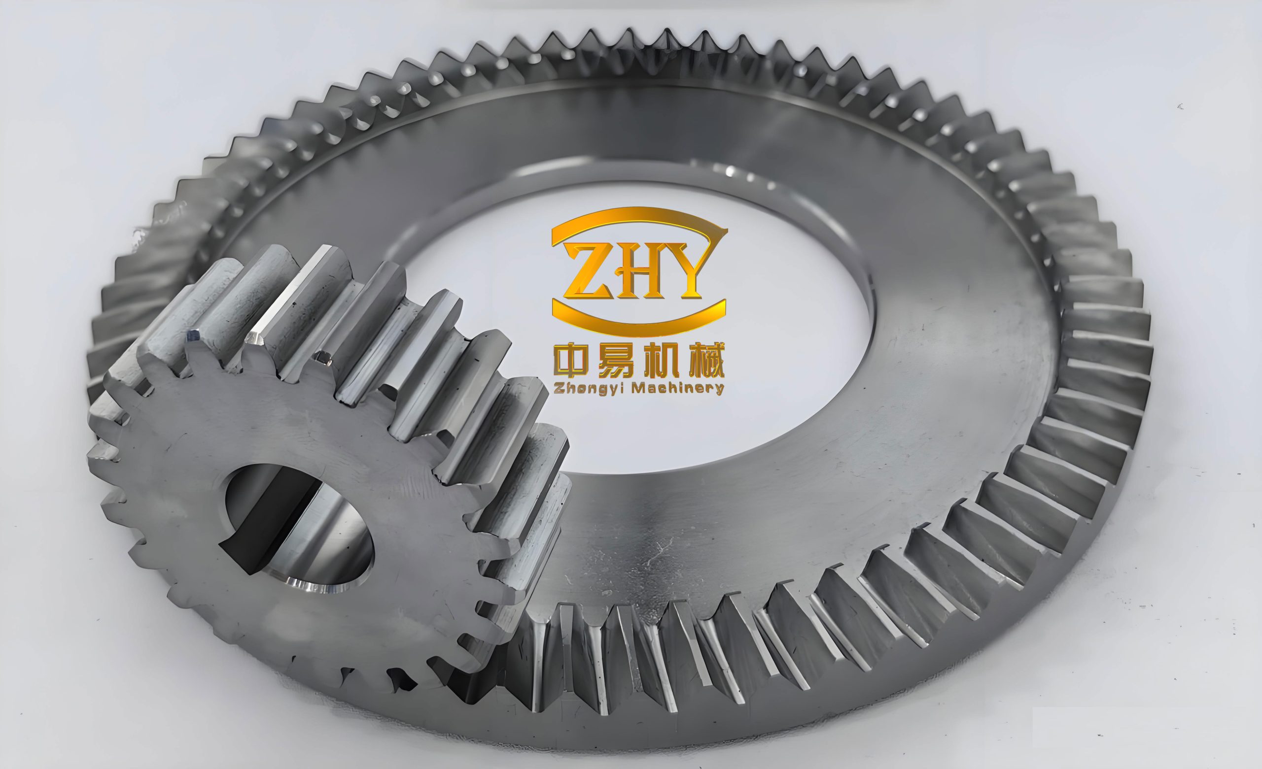
Introduction and Motivation
Face gear drives offer several advantages, including compact structure, convenient installation and adjustment, large transmission ratio, and good load distribution. These features make face gear drives attractive in aerospace, vehicle, and industrial transmission systems. However, the precision manufacturing of face gear remains challenging because the face gear tooth surface is not a simple planar or cylindrical surface. It is a generated surface that depends on the generating gear, the grinding wheel profile, the machine kinematics, and the relative position between the tool and the workpiece. In many existing approaches, face gear grinding is performed on a dedicated machine tool. Such a machine tool is expensive and is not always available in general gear manufacturing facilities. Therefore, I investigate whether a general cylindrical internal gear grinding machine can be used to grind a face gear with acceptable accuracy.
The central idea of my method is to use a dished grinding wheel as the grinding tool. The axial section of the dished grinding wheel is made consistent with the tooth profile of a generating gear. During grinding, the dished grinding wheel simulates one tooth of the generating gear. The generating gear and the face gear are assumed to be in mesh. The grinding wheel center is not stationary; it is carried by a swinging arm and moves along coordinated linear axes. The swinging motion and the linear interpolation create the equivalent rotation of the generating gear. At the same time, the face gear rotates about its own axis. The grinding wheel also moves along the tooth width direction so that the full face gear tooth surface can be ground. This approach does not require a special face gear grinding machine, and it can be implemented on a general cylindrical internal gear grinding machine with suitable numerical control axes.
Kinematic Principle
I define the generating gear as an imaginary cylindrical gear that meshes with the face gear. The dished grinding wheel represents one tooth of this generating gear. Let the generating gear rotate by angle \(\varphi_c\) and the face gear rotate by angle \(\varphi_g\). The meshing relationship between the generating gear and the face gear is governed by the gear ratio. I write the kinematic ratio as
$$ i_{cg} = \frac{\omega_g}{\omega_c} = \frac{\varphi_g}{\varphi_c} = \frac{Z_c}{Z_g} $$
where \(\omega_c\) is the angular velocity of the generating gear, \(\omega_g\) is the angular velocity of the face gear, \(Z_c\) is the number of teeth of the generating gear, and \(Z_g\) is the number of teeth of the face gear. For a face gear pair, the generating gear is usually chosen to have a small number of teeth, while the face gear has a much larger number of teeth. This ratio determines the relative rotation during the generating motion.
The machine structure that I use has several numerically controlled axes. The grinding wheel head can move along the Z direction and the Y direction. A grinding wheel arm is mounted on the wheel head and rotates about the A axis. The dished grinding wheel is installed on the wheel arm and rotates about its own spindle axis for cutting. The rotary table moves along the X direction. The face gear workpiece is mounted on the B axis and rotates with the B axis. Therefore, the machine provides coordinated motions in the X, Y, and Z linear directions and rotations about the A and B axes. I summarize the functions of these axes in Table 1.
| Axis | Type | Function in the proposed face gear grinding process |
|---|---|---|
| X | Linear | Moves the rotary table along the tooth width direction of the face gear. |
| Y | Linear | Provides horizontal interpolation to reproduce the generating gear rotation. |
| Z | Linear | Provides vertical interpolation to reproduce the generating gear rotation. |
| A | Rotary | Swing the grinding wheel arm around the generating gear center. |
| B | Rotary | Rotates the face gear workpiece according to the generating ratio. |
| C | Spindle | Rotates the dished grinding wheel for cutting. |
To make the dished grinding wheel simulate the rotation of the generating gear, the grinding wheel arm rotates about the A axis, while the wheel head moves along Y and Z. Let \(E\) be the distance between the grinding wheel center and the generating gear center, and let \(L\) be the grinding wheel arm length, which is the distance from the grinding wheel head rotation center to the grinding wheel rotation center. I define the combined distance as
$$ a = E + L $$
During the generating motion, the grinding wheel head rotation center moves along a circular arc. The interpolation displacement in the Z direction is
$$ D_Z = – \left( a – a \cos \varphi_c \right) $$
The interpolation displacement in the Y direction is
$$ D_Y = a \sin \varphi_c $$
These two equations create the equivalent swing of the generating gear. The generating gear angle \(\varphi_c\) is also the swing angle of the grinding wheel arm. The limit positions of \(\varphi_c\) are chosen so that the contact between the face gear and the generating gear covers the required working region, especially the region from the face gear outer end to the generating gear root. The face gear rotation is synchronized with the generating gear rotation through the ratio \(i_{cg}\).
At the same time, the table moves along the X direction to cover the face gear tooth width. If \(R_1\) and \(R_2\) are the inner and outer radii of the face gear, the X-axis stroke must be larger than the face gear tooth width. The face gear rotation angle satisfies
$$ \varphi_g = i_{cg} \varphi_c $$
Thus, the face gear grinding motion is a combination of X, Y, and Z translations and A and B rotations. The spindle C provides the cutting motion. I use this five-axis motion synthesis to generate the face gear tooth surface with the dished grinding wheel.
Mathematical Model of the Dished Grinding Wheel
The dished grinding wheel axial profile is the same as the profile of the generating gear. I describe the grinding wheel surface in the wheel coordinate system \(S_s\). Let \(r_b\) be the base circle radius of the generating gear. Let \(\theta_0\) be the angle from the tooth slot symmetry line to the starting point of the involute. Let \(\theta_c\) be the involute angle parameter, and let \(u_c\) be the axial parameter of a point on the grinding wheel surface. The position vector of the dished grinding wheel surface can be written as
$$ \mathbf{r}_s(\theta_c,u_c) = \begin{bmatrix} – r_b \left[ \cos(\theta_0+\theta_c) + \theta_c \sin(\theta_0+\theta_c) \right] – E \\ \pm r_b \left[ \sin(\theta_0+\theta_c) – \theta_c \cos(\theta_0+\theta_c) \right] \\ u_c \\ 1 \end{bmatrix} $$
In this expression, the plus and minus signs correspond to the two sides of the grinding wheel tooth slot. The parameter \(E\) is the distance between the grinding wheel center and the generating gear center. The parameter \(u_c\) describes the position along the wheel axis. The involute parameter \(\theta_c\) describes the position along the involute profile. This surface equation is the starting point for the face gear tooth surface generation.
I define several coordinate systems to derive the face gear tooth surface. The grinding wheel coordinate system \(S_s\) is fixed to the dished grinding wheel. The grinding wheel head moving coordinate system \(S_p\) is fixed to the grinding wheel arm and rotates with the arm around the generating gear center. The machine fixed coordinate system \(S_n\) is fixed to the machine tool. The face gear initial coordinate system \(S_m\) is fixed to the machine and aligned with the initial position of the face gear. The face gear moving coordinate system \(S_g\) is fixed to the face gear and rotates with the face gear.
The transformation matrix from the grinding wheel coordinate system \(S_s\) to the grinding wheel head moving coordinate system \(S_p\) is
$$ \mathbf{M}_{p,s} = \begin{bmatrix} 0 & 0 & 1 & 0 \\ 0 & 1 & 0 & 0 \\ -1 & 0 & 0 & -L \\ 0 & 0 & 0 & 1 \end{bmatrix} $$
The transformation matrix from the grinding wheel head moving coordinate system \(S_p\) to the machine fixed coordinate system \(S_n\) is
$$ \mathbf{M}_{n,p}(\varphi_c) = \begin{bmatrix} 1 & 0 & 0 & 0 \\ 0 & \cos\varphi_c & \sin\varphi_c & a \sin\varphi_c \\ 0 & -\sin\varphi_c & \cos\varphi_c & -a(1-\cos\varphi_c) \\ 0 & 0 & 0 & 1 \end{bmatrix} $$
The transformation matrix from the machine fixed coordinate system \(S_n\) to the face gear initial coordinate system \(S_m\) is
$$ \mathbf{M}_{m,n} = \begin{bmatrix} 1 & 0 & 0 & 0 \\ 0 & 1 & 0 & 0 \\ 0 & 0 & 1 & a \\ 0 & 0 & 0 & 1 \end{bmatrix} $$
The transformation matrix from the face gear initial coordinate system \(S_m\) to the face gear moving coordinate system \(S_g\) is
$$ \mathbf{M}_{g,m} = \begin{bmatrix} \cos\varphi_g & \sin\varphi_g & 0 & 0 \\ -\sin\varphi_g & \cos\varphi_g & 0 & 0 \\ 0 & 0 & 1 & 0 \\ 0 & 0 & 0 & 1 \end{bmatrix} $$
Using these transformations, the grinding wheel surface can be represented in the face gear coordinate system as
$$ \mathbf{r}_g(\varphi_c,u_c,\theta_c) = \mathbf{M}_{g,m} \mathbf{M}_{m,n} \mathbf{M}_{n,p} \mathbf{M}_{p,s} \mathbf{r}_s(\theta_c,u_c) $$
During the generating motion, the grinding wheel surface and the face gear tooth surface must satisfy the meshing equation. The meshing equation can be written as
$$ f_1(\theta_c,u_c,\varphi_c) = \left( \frac{\partial \mathbf{r}_g}{\partial \theta_c} \times \frac{\partial \mathbf{r}_g}{\partial u_c} \right) \cdot \frac{\partial \mathbf{r}_g}{\partial \varphi_c} = 0 $$
This equation expresses the condition that the relative velocity between the tool surface and the face gear tooth surface is perpendicular to the common normal at the contact point. For a point on the face gear tooth surface, I also define its position in the rotation projection plane. Let \(R\) be the radial coordinate and \(Z\) be the axial coordinate in the rotation projection plane. The position equations are
$$ f_2(\theta_c,u_c,\varphi_c) = r_{gx}^2(\theta_c,u_c,\varphi_c) + r_{gy}^2(\theta_c,u_c,\varphi_c) – R = 0 $$
$$ f_3(\theta_c,u_c,\varphi_c) = r_{gz}(\theta_c,u_c,\varphi_c) – Z = 0 $$
For a specified point \((R,Z)\) on the tooth surface, I solve the nonlinear system formed by \(f_1\), \(f_2\), and \(f_3\) to obtain the three unknown parameters \(\theta_c\), \(u_c\), and \(\varphi_c\). Substituting these parameters into the face gear tooth surface equation gives the corresponding tooth surface coordinate. The tooth surface obtained in this way is theoretically identical to the tooth surface generated by a gear shaping cutter with the same generating gear profile.
Machine Parameter Error Model
In actual grinding, the machine tool parameters may deviate from their nominal values. These deviations change the relative position between the dished grinding wheel and the face gear, and therefore change the generated face gear tooth surface. I focus on three key machine parameter errors: the grinding wheel arm installation error \(\Delta y\), the grinding wheel installation error \(\Delta s\), and the grinding wheel arm length error \(\Delta l\). These errors are closely related to the actual machine structure and can be adjusted or compensated in practice.
The grinding wheel arm installation error \(\Delta y\) represents the position error between the grinding wheel head rotation center and the grinding wheel rotation center in the Y direction. The grinding wheel installation error \(\Delta s\) represents the lateral offset between the grinding wheel centerline and the dressing wheel centerline after dressing. The grinding wheel arm length error \(\Delta l\) represents the difference between the actual arm length and the designed arm length \(L\).
With these errors included, the transformation matrix from the grinding wheel coordinate system \(S_s\) to the grinding wheel head moving coordinate system \(S_p\) becomes
$$ \mathbf{M}’_{p,s} = \begin{bmatrix} 0 & 0 & 1 & 0 \\ 0 & 1 & 0 & \Delta s \\ -1 & 0 & 0 & -L + \Delta l \\ 0 & 0 & 0 & 1 \end{bmatrix} $$
The transformation matrix from the grinding wheel head moving coordinate system \(S_p\) to the machine fixed coordinate system \(S_n\) becomes
$$ \mathbf{M}’_{n,p}(\varphi_c) = \begin{bmatrix} 1 & 0 & 0 & 0 \\ 0 & \cos\varphi_c & \sin\varphi_c & (a+\Delta l)\sin\varphi_c + \Delta y \\ 0 & -\sin\varphi_c & \cos\varphi_c & -(a+\Delta l)(1-\cos\varphi_c) \\ 0 & 0 & 0 & 1 \end{bmatrix} $$
Replacing the nominal transformation matrices with the error matrices, the face gear tooth surface position vector containing machine parameter errors is
$$ \mathbf{r}_{g2}(\varphi_c,u_c,\theta_c) = \mathbf{M}_{g,m} \mathbf{M}_{m,n} \mathbf{M}’_{n,p} \mathbf{M}’_{p,s} \mathbf{r}_s(\theta_c,u_c) $$
This equation allows me to calculate the actual face gear tooth surface produced by the machine when the three parameter errors are present. By comparing the actual tooth surface with the theoretical tooth surface, I can evaluate the influence of each error on the face gear tooth surface topology.
Tooth Surface Deviation and Grid Definition
I evaluate the face gear tooth surface deviation in the working tooth surface region. The transition surface does not participate in meshing, so I exclude it from the deviation analysis. For the working tooth surface, I define a detection region with a 5% tooth height shrinkage at the addendum and dedendum and a 10% tooth width shrinkage at the toe and heel. This region is divided into a grid with five rows and nine columns. The grid provides a systematic representation of the tooth surface topology.
For each grid point \((i,j)\), I calculate the theoretical tooth surface position vector \(\mathbf{r}_g(i,j)\) and the theoretical normal vector \(\mathbf{n}_g(i,j)\). The normal vector is obtained from the cross product of the two partial derivatives of the tooth surface position vector:
$$ \mathbf{n}_g(i,j) = \frac{\partial \mathbf{r}_g}{\partial \theta_c} \times \frac{\partial \mathbf{r}_g}{\partial u_c} $$
I define the actual tooth surface position vector at the same grid point as \(\mathbf{R}_v(i,j)\). The deviation at the grid point is the projection of the difference between the theoretical and actual position vectors onto the theoretical normal direction. The deviation is
$$ e(i,j) = \left[ \mathbf{r}_g(i,j) – \mathbf{R}_v(i,j) \right] \cdot \mathbf{n}_g(i,j) $$
I choose the center point of the tooth surface grid as the reference point. At the reference point, the actual tooth surface is assumed to coincide with the theoretical tooth surface, so the deviation at this point is zero. This convention removes the rigid body positioning error and allows the deviation pattern to reflect the topological shape error of the face gear tooth surface.
Table 2 lists the basic parameters of the face gear pair used in my analysis and experiments. These parameters define the generating gear, the face gear, and the geometric limits of the tooth surface.
| Parameter | Symbol | Value |
|---|---|---|
| Pinion tooth number | \(Z_1\) | 21 |
| Generating gear tooth number | \(Z_c\) | 24 |
| Face gear tooth number | \(Z_g\) | 120 |
| Shaft angle | \(\gamma\) | \(90^\circ\) |
| Normal module | \(m_n\) | 4.0 mm |
| Pressure angle | \(\alpha_k\) | \(25^\circ\) |
| Face gear inner radius | \(R_1\) | 220 mm |
| Face gear outer radius | \(R_2\) | 270 mm |
Influence of Machine Parameter Errors
I analyze the influence of \(\Delta y\), \(\Delta s\), and \(\Delta l\) on the face gear tooth surface topology. The results show that each error produces a distinct deviation pattern. Understanding these patterns is important because it allows me to identify the dominant error source from measured tooth surface deviations and to correct the machine parameters accordingly.
The grinding wheel arm installation error \(\Delta y\) mainly causes a pressure angle deviation. The pressure angle changes in opposite directions on the left and right tooth surfaces. When \(\Delta y\) increases, the left tooth surface pressure angle decreases, and the right tooth surface pressure angle increases. When \(\Delta y\) decreases, the left tooth surface pressure angle increases, and the right tooth surface pressure angle decreases. This opposite behavior is useful for distinguishing \(\Delta y\) from other errors.
The grinding wheel installation error \(\Delta s\) mainly causes a change in the face gear spiral angle. Increasing \(\Delta s\) makes the face gear tooth trace tend toward a right-hand direction. Decreasing \(\Delta s\) makes the face gear tooth trace tend toward a left-hand direction. This error therefore appears primarily as a tooth width direction deviation rather than a pressure angle deviation.
The grinding wheel arm length error \(\Delta l\) mainly causes a tooth surface twist deviation, and it also introduces a pressure angle deviation. The influence is most significant near the small end and the tooth root. Increasing \(\Delta l\) increases the pressure angle on both left and right tooth surfaces. Decreasing \(\Delta l\) decreases the pressure angle on both left and right tooth surfaces. Because \(\Delta l\) affects both flanks in the same pressure angle direction and also produces twist, it can be separated from \(\Delta y\), which affects the two flanks in opposite directions.
I summarize the qualitative influence of the three machine parameter errors in Table 3. This table is used as a guide for correcting the face gear grinding process.
| Error | Dominant deviation pattern | Effect of increasing the error | Effect of decreasing the error |
|---|---|---|---|
| \(\Delta y\) | Pressure angle deviation | Left pressure angle decreases; right pressure angle increases | Left pressure angle increases; right pressure angle decreases |
| \(\Delta s\) | Spiral angle or tooth trace deviation | Tooth trace tends to right-hand direction | Tooth trace tends to left-hand direction |
| \(\Delta l\) | Twist and pressure angle deviation | Both flank pressure angles increase; twist changes | Both flank pressure angles decrease; twist changes |
Sensitivity Matrix and Correction Strategy
To correct the face gear tooth surface deviations, I construct a sensitivity matrix that relates the machine parameter errors to the tooth surface deviations. Let the vector of machine parameter errors be
$$ \mathbf{q} = \begin{bmatrix} \Delta y \\ \Delta s \\ \Delta l \end{bmatrix} $$
Let the vector of tooth surface deviations at the selected grid points be \(\mathbf{e}\). The sensitivity matrix \(\mathbf{S}\) contains the partial derivatives of the tooth surface deviations with respect to the machine parameter errors. For a small error vector, I approximate the deviation vector by the linear relation
$$ \mathbf{e} \approx \mathbf{S} \mathbf{q} $$
The sensitivity matrix can be written as
$$ \mathbf{S} = \begin{bmatrix} \frac{\partial e_1}{\partial \Delta y} & \frac{\partial e_1}{\partial \Delta s} & \frac{\partial e_1}{\partial \Delta l} \\ \frac{\partial e_2}{\partial \Delta y} & \frac{\partial e_2}{\partial \Delta s} & \frac{\partial e_2}{\partial \Delta l} \\ \vdots & \vdots & \vdots \\ \frac{\partial e_m}{\partial \Delta y} & \frac{\partial e_m}{\partial \Delta s} & \frac{\partial e_m}{\partial \Delta l} \end{bmatrix} $$
Because the number of measured grid points is larger than the number of unknown machine parameter errors, the system is overdetermined. I solve for the correction vector in the least-squares sense:
$$ \mathbf{q} = \left( \mathbf{S}^{\mathrm{T}} \mathbf{S} \right)^{-1} \mathbf{S}^{\mathrm{T}} \mathbf{e} $$
This equation gives the estimated corrections for \(\Delta y\), \(\Delta s\), and \(\Delta l\). In practice, I adjust the machine tool according to these values, grind a new face gear, measure the tooth surface again, and repeat the procedure if necessary. The procedure converges rapidly when the initial errors are not extremely large.
I also use the sensitivity information to understand which machine parameter dominates a particular measured deviation pattern. For example, if the measured deviation shows opposite pressure angle changes on the left and right flanks, I assign a large contribution to \(\Delta y\). If the measured deviation shows a clear tooth trace direction change, I assign a large contribution to \(\Delta s\). If the measured deviation shows a symmetric pressure angle change together with twist, I assign a large contribution to \(\Delta l\). This diagnosis makes the correction process systematic rather than trial-and-error.
Experimental Setup and Initial Grinding Results
I performed face gear grinding experiments on a cylindrical internal gear grinding machine. The machine is equipped with the required linear and rotary axes. I mounted the face gear workpiece on the rotary table and used a dished grinding wheel dressed to the generating gear profile. The machine parameters were set according to the theoretical model. After the initial setup, I ground the face gear and measured the tooth surface using a Gleason gear inspection center. The measurement provided the tooth surface deviation distribution over the working region.
The initial grinding results showed that the face gear tooth surface deviated from the theoretical surface. The left tooth surface deviation ranged from -87 μm to 176 μm. The right tooth surface deviation ranged from -98.6 μm to 166.8 μm. The deviation pattern indicated errors in both pressure angle and spiral angle. These deviations were larger than the desired accuracy and confirmed that the machine parameter errors had a significant influence on the generated face gear tooth surface.
Using the measured deviation field and the sensitivity matrix, I calculated the required machine parameter corrections. The corrections were
$$ \Delta y = 0.09 \ \text{mm} $$
$$ \Delta s = 0.13 \ \text{mm} $$
$$ \Delta l = -0.32 \ \text{mm} $$
I applied these corrections to the machine tool settings and ground the face gear again. After the second grinding pass, I measured the tooth surface with the same inspection procedure. The corrected left tooth surface deviation ranged from -24.6 μm to 23.8 μm. The corrected right tooth surface deviation ranged from -21.4 μm to 17 μm. The maximum deviation was -24.6 μm, and the largest deviations were located away from the main contact region. This result verified the feasibility of the proposed face gear grinding method and the correctness of the machine parameter adjustment method.
Table 4 summarizes the initial and corrected tooth surface deviations. The comparison shows a substantial reduction in both the pressure angle deviation and the spiral angle deviation.
| Stage | Left tooth surface deviation | Right tooth surface deviation | Main deviation pattern |
|---|---|---|---|
| Initial grinding | -87 μm to 176 μm | -98.6 μm to 166.8 μm | Pressure angle and spiral angle errors |
| After correction | -24.6 μm to 23.8 μm | -21.4 μm to 17 μm | Small residual topology deviation |
Table 5 lists the correction values obtained from the sensitivity analysis and applied to the machine tool. These values are specific to the experimental setup and the initial machine condition, but the correction methodology is general.
| Machine parameter error | Correction value |
|---|---|
| \(\Delta y\) | 0.09 mm |
| \(\Delta s\) | 0.13 mm |
| \(\Delta l\) | -0.32 mm |
Discussion
The experimental results demonstrate that a general cylindrical internal gear grinding machine can be used to grind a face gear when the machine axes are properly coordinated and the dished grinding wheel is correctly profiled. The proposed method does not require a dedicated face gear grinding machine. This is important because dedicated face gear machines are expensive and not widely available. By using a general machine tool, the manufacturing cost of face gear can be reduced, and the application of face gear transmissions can be promoted.
The mathematical model developed in this work provides a complete description of the face gear grinding process. The model includes the generating ratio, the interpolation motion of the grinding wheel head, the dished grinding wheel surface, the coordinate transformations, and the meshing equation. The tooth surface equation containing machine parameter errors allows me to predict the effect of machine setting errors on the face gear tooth surface. The error analysis shows that \(\Delta y\), \(\Delta s\), and \(\Delta l\) produce different deviation patterns, which can be used for diagnosis and correction.
The sensitivity matrix method is effective for correcting the face gear tooth surface deviations. The initial deviations were relatively large, but after one correction cycle, the deviations were reduced to the range of -24.6 μm to 23.8 μm on the left flank and -21.4 μm to 17 μm on the right flank. These values are acceptable for many practical applications and can be further improved by additional correction cycles or by including more error parameters in the model.
Several factors can affect the final accuracy of the face gear grinding process. These factors include the accuracy of the grinding wheel profile, the dressing accuracy, the thermal deformation of the machine tool, the stiffness of the grinding system, the measurement uncertainty, and the repeatability of the machine axes. In my experiments, I focused on the three dominant machine parameter errors. In future work, I can extend the sensitivity matrix to include additional error sources, such as spindle tilt, table position error, and workholding error. I can also use on-machine measurement or closed-loop compensation to improve the efficiency of the correction process.
The face gear tooth surface is a complex generated surface. Its accuracy depends on the relative motion between the tool and the workpiece. The use of a dished grinding wheel is advantageous because the wheel profile can be dressed accurately and efficiently. The grinding wheel represents one tooth of the generating gear, so the generating motion is continuous and controllable. Compared with worm wheel grinding, the dished wheel grinding method has lower tool dressing difficulty. Compared with single-tooth generating grinding, the proposed method can be implemented on a general machine tool with coordinated axes. Therefore, it provides a balanced solution for face gear manufacturing.
Additional Mathematical Details
For completeness, I present the expanded form of the face gear tooth surface calculation. Substituting the transformation matrices into the position vector equation, I obtain
$$ \mathbf{r}_g = \begin{bmatrix} r_{gx} \\ r_{gy} \\ r_{gz} \\ 1 \end{bmatrix} $$
The radial coordinate in the rotation projection plane is
$$ R = \sqrt{r_{gx}^2 + r_{gy}^2} $$
The axial coordinate in the rotation projection plane is
$$ Z = r_{gz} $$
The normal vector of the face gear tooth surface is
$$ \mathbf{n}_g = \begin{bmatrix} n_{gx} \\ n_{gy} \\ n_{gz} \end{bmatrix} = \frac{\partial \mathbf{r}_g}{\partial \theta_c} \times \frac{\partial \mathbf{r}_g}{\partial u_c} $$
The unit normal vector is
$$ \hat{\mathbf{n}}_g = \frac{\mathbf{n}_g}{\|\mathbf{n}_g\|} $$
The meshing equation can also be expressed in terms of the relative velocity. Let \(\mathbf{v}^{(cg)}\) be the relative velocity between the generating gear and the face gear. The meshing condition is
$$ \mathbf{n}_g \cdot \mathbf{v}^{(cg)} = 0 $$
This condition is equivalent to the cross-product form used earlier. During the numerical solution, I solve for the parameters \(\theta_c\), \(u_c\), and \(\varphi_c\) that satisfy the meshing equation and the position equations. The Newton-Raphson method can be used to solve the nonlinear system. The Jacobian matrix of the system is
$$ \mathbf{J} = \begin{bmatrix} \frac{\partial f_1}{\partial \theta_c} & \frac{\partial f_1}{\partial u_c} & \frac{\partial f_1}{\partial \varphi_c} \\ \frac{\partial f_2}{\partial \theta_c} & \frac{\partial f_2}{\partial u_c} & \frac{\partial f_2}{\partial \varphi_c} \\ \frac{\partial f_3}{\partial \theta_c} & \frac{\partial f_3}{\partial u_c} & \frac{\partial f_3}{\partial \varphi_c} \end{bmatrix} $$
The iteration formula is
$$ \begin{bmatrix} \theta_c \\ u_c \\ \varphi_c \end{bmatrix}^{(k+1)} = \begin{bmatrix} \theta_c \\ u_c \\ \varphi_c \end{bmatrix}^{(k)} – \mathbf{J}^{-1} \begin{bmatrix} f_1 \\ f_2 \\ f_3 \end{bmatrix}^{(k)} $$
This numerical procedure allows me to generate the theoretical face gear tooth surface with high accuracy. The same procedure is used with the error transformation matrices to generate the actual tooth surface under machine parameter errors.
Error Sensitivity Formulation
The sensitivity of the tooth surface deviation to a machine parameter error can be expressed as the derivative of the deviation function with respect to the error. For a general error parameter \(q\), the sensitivity is
$$ \frac{\partial e}{\partial q} = \frac{\partial}{\partial q} \left[ \left( \mathbf{r}_g – \mathbf{R}_v \right) \cdot \mathbf{n}_g \right] $$
Because the actual tooth surface \(\mathbf{R}_v\) depends on the error parameter \(q\), I can write
$$ \frac{\partial e}{\partial q} = \frac{\partial \mathbf{r}_g}{\partial q} \cdot \mathbf{n}_g + \left( \mathbf{r}_g – \mathbf{R}_v \right) \cdot \frac{\partial \mathbf{n}_g}{\partial q} – \frac{\partial \mathbf{R}_v}{\partial q} \cdot \mathbf{n}_g $$
For small errors, the second term is small because the deviation is small compared with the tooth surface dimensions. The dominant term is the difference between the derivative of the theoretical surface and the derivative of the actual surface. In the linear sensitivity model, I approximate the sensitivity by the derivative of the theoretical tooth surface with respect to the error parameter:
$$ \frac{\partial e}{\partial q} \approx \frac{\partial \mathbf{r}_g}{\partial q} \cdot \mathbf{n}_g $$
This approximation is sufficient for the correction procedure because the initial deviations are reduced iteratively. The sensitivity matrix is assembled by evaluating these derivatives at all selected grid points on the tooth surface.
Numerical Example of Correction
I illustrate the correction calculation with a simplified example. Suppose the measured deviation vector contains two dominant components: an opposite pressure angle deviation on the left and right flanks and a tooth trace deviation. The sensitivity matrix has the form
$$ \mathbf{S} = \begin{bmatrix} s_{11} & s_{12} & s_{13} \\ s_{21} & s_{22} & s_{23} \\ s_{31} & s_{32} & s_{33} \\ s_{41} & s_{42} & s_{43} \end{bmatrix} $$
where the first column corresponds to \(\Delta y\), the second column to \(\Delta s\), and the third column to \(\Delta l\). The measured deviation vector is
$$ \mathbf{e} = \begin{bmatrix} e_1 \\ e_2 \\ e_3 \\ e_4 \end{bmatrix} $$
The least-squares solution is
$$ \mathbf{q} = \left( \mathbf{S}^{\mathrm{T}} \mathbf{S} \right)^{-1} \mathbf{S}^{\mathrm{T}} \mathbf{e} $$
Using the measured deviations and the computed sensitivities, I obtained the correction values listed in Table 5. After applying these corrections, the maximum face gear tooth surface deviation was reduced to -24.6 μm. This result shows that the sensitivity matrix method is practical for face gear grinding on a general machine tool.
Comparison with Dedicated Face Gear Grinding
Dedicated face gear grinding machines are designed specifically for face gear production. They usually have a special structure and kinematics that are optimized for the generating motion. However, such machines are expensive and require specialized tooling. My proposed method uses a general cylindrical internal gear grinding machine. The machine already has the required linear and rotary axes, and the dished grinding wheel can be dressed with a standard dressing device. The main challenge is to coordinate the machine axes correctly and to compensate for machine parameter errors. Once the mathematical model and correction procedure are established, the general machine can produce face gears with acceptable accuracy. This approach reduces the entry barrier for face gear manufacturing and makes small-batch and medium-batch production more economical.
Table 6 compares the proposed method with dedicated face gear grinding in terms of machine requirement, tooling, flexibility, and cost. The comparison is qualitative and is based on the practical considerations of the face gear grinding process.
| Item | Dedicated face gear grinding | Proposed method on cylindrical internal gear grinding machine |
|---|---|---|
| Machine requirement | Special machine tool | General machine tool with coordinated axes |
| Tooling | Special face gear grinding wheel system | Dished grinding wheel with generating gear profile |
| Flexibility | Limited to designed face gear types | Adaptable through numerical control and parameter correction |
| Cost | High | Lower for small and medium batch production |
| Accuracy potential | High with optimized machine | High after parameter correction |
Practical Implementation Steps
I summarize the practical implementation of the proposed face gear grinding method in the following steps:
1. Determine the face gear geometry and the generating gear parameters. Calculate the gear ratio \(i_{cg} = Z_c / Z_g\).
2. Dress the dished grinding wheel so that its axial profile matches the generating gear tooth profile. Ensure that the wheel installation error is minimized during dressing.
3. Set the machine axes according to the theoretical kinematic model. The grinding wheel arm swing angle is \(\varphi_c\), and the face gear rotation is \(\varphi_g = i_{cg} \varphi_c\). The Y and Z interpolation displacements are \(D_Y = a \sin\varphi_c\) and \(D_Z = -(a – a\cos\varphi_c)\).
4. Move the table along the X direction to cover the entire face gear tooth width from the inner radius \(R_1\) to the outer radius \(R_2\).
5. Grind the face gear and measure the tooth surface on a gear inspection center. Record the deviation grid over the working region.
6. Calculate the sensitivity matrix \(\mathbf{S}\) for the selected machine parameter errors. Solve for the correction vector \(\mathbf{q}\) using the least-squares equation.
7. Adjust the machine parameters \(\Delta y\), \(\Delta s\), and \(\Delta l\) according to the correction vector. Regrind and remeasure the face gear. Repeat if necessary.
8. Confirm the final tooth surface deviation. In my experiment, the final maximum deviation was -24.6 μm, which validated the procedure.
Further Error Sources and Extensions
Although I focused on three machine parameter errors, other error sources can also affect the face gear tooth surface. For example, spindle tilt error can change the effective wheel profile orientation. Table position error can shift the contact line along the tooth width. Workpiece clamping error can introduce a runout that varies with the face gear rotation. Thermal deformation can change the machine geometry during long grinding cycles. These errors can be included in the mathematical model by introducing additional transformation matrices or by extending the sensitivity matrix.
If I define an extended error vector
$$ \mathbf{q}_{\mathrm{ext}} = \begin{bmatrix} \Delta y \\ \Delta s \\ \Delta l \\ \Delta \alpha \\ \Delta \beta \\ \Delta \gamma \\ \vdots \end{bmatrix} $$
then the extended sensitivity matrix becomes
$$ \mathbf{S}_{\mathrm{ext}} = \begin{bmatrix} \frac{\partial e_1}{\partial q_1} & \frac{\partial e_1}{\partial q_2} & \cdots \\ \frac{\partial e_2}{\partial q_1} & \frac{\partial e_2}{\partial q_2} & \cdots \\ \vdots & \vdots & \ddots \end{bmatrix} $$
The correction vector is still obtained by least squares:
$$ \mathbf{q}_{\mathrm{ext}} = \left( \mathbf{S}_{\mathrm{ext}}^{\mathrm{T}} \mathbf{S}_{\mathrm{ext}} \right)^{-1} \mathbf{S}_{\mathrm{ext}}^{\mathrm{T}} \mathbf{e} $$
This extension allows the method to compensate for more complex error patterns. However, adding too many parameters can reduce the robustness of the correction if the measurement data are noisy. Therefore, I recommend selecting the dominant error parameters based on the measured deviation pattern and the machine condition.
Verification of the Face Gear Tooth Surface
The experimental verification was performed on a Gleason gear inspection center. The inspection data showed the deviation distribution over the working tooth surface. The initial deviations were dominated by pressure angle and spiral angle errors. After correcting \(\Delta y\), \(\Delta s\), and \(\Delta l\), the deviations were significantly reduced. The maximum deviation after correction was -24.6 μm. The largest residual deviations were located away from the main contact region, which means that the contact performance of the face gear pair would not be severely affected. This result confirms that the proposed face gear grinding method is feasible and that the machine parameter adjustment method is correct.
Table 7 presents a summary of the verification results. The table includes the initial deviation range, the correction values, and the final deviation range. These results provide a clear quantitative demonstration of the effectiveness of the proposed method.
| Verification item | Result |
|---|---|
| Initial left flank deviation | -87 μm to 176 μm |
| Initial right flank deviation | -98.6 μm to 166.8 μm |
| Correction for \(\Delta y\) | 0.09 mm |
| Correction for \(\Delta s\) | 0.13 mm |
| Correction for \(\Delta l\) | -0.32 mm |
| Final left flank deviation | -24.6 μm to 23.8 μm |
| Final right flank deviation | -21.4 μm to 17 μm |
| Maximum final deviation | -24.6 μm |
Conclusions
I have proposed a method for grinding a face gear on a general cylindrical internal gear grinding machine using a dished grinding wheel. The method uses the coordinated motion of the machine axes to simulate the generating motion between an imaginary generating gear and the face gear. I established the mathematical model of the face gear grinding process, including the kinematic ratio, the wheel head interpolation, the dished grinding wheel surface, the coordinate transformations, and the meshing equation. I derived the face gear tooth surface equation with machine parameter errors and analyzed the influence of the grinding wheel arm installation error, the grinding wheel installation error, and the grinding wheel arm length error on the tooth surface topology.
I constructed a sensitivity matrix to relate the machine parameter errors to the face gear tooth surface deviations. The sensitivity matrix method provides a systematic way to calculate the correction values for the machine parameters. I performed face gear grinding experiments on a cylindrical internal gear grinding machine and measured the tooth surfaces on a Gleason gear inspection center. The initial deviations were reduced from -87 μm to 176 μm and -98.6 μm to 166.8 μm to final ranges of -24.6 μm to 23.8 μm and -21.4 μm to 17 μm. The maximum final deviation was -24.6 μm.
The experimental results verified that the proposed face gear grinding method has no principle error and that the machine parameter correction method is effective. The method does not require a dedicated face gear grinding machine. This is significant for the promotion of face gear applications and for reducing manufacturing costs. In future work, I will extend the error model to include more machine error sources, improve the numerical efficiency of the tooth surface solution, and investigate the influence of the corrected face gear tooth surface on the loaded contact behavior of the face gear pair.
Key Symbols and Definitions
| Symbol | Definition |
|---|---|
| \(Z_c\) | Number of teeth of the generating gear |
| \(Z_g\) | Number of teeth of the face gear |
| \(\varphi_c\) | Generating gear rotation angle or grinding wheel arm swing angle |
| \(\varphi_g\) | Face gear rotation angle |
| \(i_{cg}\) | Gear ratio between the generating gear and the face gear |
| \(E\) | Distance between the grinding wheel center and the generating gear center |
| \(L\) | Grinding wheel arm length |
| \(a\) | Combined distance \(E+L\) |
| \(D_Y\) | Y-direction interpolation displacement |
| \(D_Z\) | Z-direction interpolation displacement |
| \(r_b\) | Base circle radius of the generating gear |
| \(\theta_c\) | Involute angle parameter |
| \(u_c\) | Axial parameter on the grinding wheel surface |
| \(\Delta y\) | Grinding wheel arm installation error |
| \(\Delta s\) | Grinding wheel installation error |
| \(\Delta l\) | Grinding wheel arm length error |
| \(e(i,j)\) | Tooth surface deviation at grid point \((i,j)\) |
| \(\mathbf{S}\) | Sensitivity matrix |
| \(\mathbf{q}\) | Machine parameter correction vector |
This work shows that a general cylindrical internal gear grinding machine can be used for face gear grinding when the generating motion is correctly modeled and the machine parameter errors are properly corrected. The proposed face gear grinding method provides a practical and economical route for face gear manufacturing, and the sensitivity-based correction method provides a reliable way to achieve the required face gear tooth surface accuracy.