
I investigated the strengthening of face gears by laser cladding and the subsequent grinding of the deposited layer. My objective was to improve the hardness and wear resistance of face gears that operate under high-speed and heavy-load conditions. Face gears are attractive transmission components because they can transfer motion between intersecting axes with a compact structure, a favorable load-sharing ability, and a high load-carrying capacity. However, the same severe service conditions that make face gears useful also make them vulnerable to wear, scuffing, and fatigue failure. I therefore used a nickel-based self-fluxing alloy as a transition layer and a NiCr-Cr3C2 cermet as the hard surface layer. I first optimized the laser cladding process on flat coupons, then applied the selected parameters to real face gears, and finally ground the clad tooth surfaces to restore geometry and accuracy.
In my study, the substrate was 20Cr2Ni4A steel, a common material for heavy-duty gears. The transition powder was Ni45, which has moderate hardness, good toughness, and good compatibility with many metallic substrates. The hard surface powder was NiCr-Cr3C2, a cermet composite consisting of NiCr alloy and Cr3C2 particles. This combination allowed me to create a graded structure from the substrate to the surface. Such a gradient is important because a direct cermet coating on steel can generate high interfacial stresses, cracks, and poor bonding. By inserting Ni45 between the steel and the cermet, I obtained a smoother hardness transition and a stronger metallurgical bond.
The chemical compositions I used are summarized below. These values controlled the dilution behavior, the formation of hard phases, and the final wear resistance of the clad face gears.
| Element | C | Cr | Mn | Si | P | S | Ni |
|---|---|---|---|---|---|---|---|
| 20Cr2Ni4A substrate, wt.% | 0.21 | 1.35 | 2.20 | 0.38 | 0.02 | 0.02 | 3.46 |
| Element | C | Cr | B | Si | Fe | Ni |
|---|---|---|---|---|---|---|
| Ni45 powder, wt.% | 0.06 | 7.52 | 2.20 | 3.50 | 3.62 | 83.10 |
| Constituent | Ni | Cr | C | Si | Fe | O |
|---|---|---|---|---|---|---|
| NiCr fraction in cermet, wt.% | 79.50 | 19.60 | – | 0.64 | 0.31 | 0.25 |
| Cr3C2 fraction in cermet, wt.% | – | 84.72 | 13.40 | 0.01 | – | 0.13 |
For the laser cladding experiments I used a fiber laser, a six-axis robot, a coaxial powder feeding head, and a twin-channel powder feeder. The beam wavelength was in the near-infrared range, which is absorbed well by metallic powders and reasonably well by ceramic particles. I cleaned the substrate with abrasive paper and ethanol before cladding. After cladding, I sectioned the samples, polished them, etched them, and examined the microstructure with optical microscopy, scanning electron microscopy, energy-dispersive spectroscopy, and X-ray diffraction. I measured microhardness with a Vickers indenter and wear behavior with a high-temperature friction and wear tester.
The interaction between the laser and the material determined the shape, dilution, and quality of the clad layer. I considered the energy balance at the irradiated surface as
$$E_0 = E_r + E_a$$
where \(E_0\) is the incident laser energy, \(E_r\) is the reflected energy, and \(E_a\) is the absorbed energy. Dividing by \(E_0\) gave
$$1 = R + A = \frac{E_r}{E_0} + \frac{E_a}{E_0}$$
where \(R\) is reflectance and \(A\) is absorptance. For metallic materials, the absorptance depends on resistivity, wavelength, temperature, and surface roughness. For ceramic phases, the absorption behavior differs from that of metals, and the near-infrared wavelength of the fiber laser was beneficial for heating both the NiCr alloy and the Cr3C2 particles. I also considered that surface roughness increases diffuse reflection and can improve absorption. Preheating the substrate, selecting an appropriate wavelength, and choosing a suitable powder were all effective ways to improve energy coupling.
The laser power density in a Gaussian beam can be written as
$$I(r,0) = I_0 \exp\left(-\frac{2r^2}{R_b^2}\right)$$
where \(I_0\) is the peak power density, \(r\) is the radial distance from the beam center, and \(R_b\) is the beam radius. The total power is
$$P = \int_0^\infty I(r,0) 2\pi r\,dr = \frac{1}{2}\pi R_b^2 I_0$$
Combining these relations gave
$$I(r,0) = \frac{2P}{\pi R_b^2}\exp\left(-\frac{2r^2}{R_b^2}\right)$$
At a depth \(z\) below the surface, I used an exponential attenuation model:
$$I(z) = I(0)\exp(-Az)$$
The temperature distribution associated with a stationary beam can be approximated as
$$T(z,r) = \frac{P}{2\pi K R_b^2}\exp\left(-\frac{2r^2}{R_b^2}-Az\right)$$
where \(K\) is thermal conductivity. From this relation, the maximum cladding depth is controlled by the surface vaporization temperature, the melting temperature, and the absorption coefficient. I used this reasoning to avoid excessive power that would cause evaporation or excessive dilution, and to avoid insufficient power that would leave unmelted powder on the face gears.
Cladding quality also depends on the geometry of a single track. I characterized each track by its height \(H\), width \(W\), penetration depth \(h\), and contact angle \(\theta\). The contact angle is especially important for multi-track cladding because it controls whether adjacent tracks overlap smoothly or trap pores and oxides. I used the relation
$$\theta = 180^\circ – 2\arctan\left(\frac{H}{W}\right)$$
For good overlap and low crack susceptibility, I aimed for a contact angle between \(120^\circ\) and \(150^\circ\). This corresponded approximately to
$$0.14 \lt \frac{H}{W} \lt 0.28$$
Dilution was another critical factor. I defined dilution as
$$\eta = \frac{h}{H+h}$$
A very small dilution can cause poor bonding, while a very large dilution can degrade the coating by excessive mixing with the substrate. For the face gears, I wanted enough dilution to form a metallurgical bond but not so much that the hard cermet layer lost its beneficial composition. In my experiments, the best results were obtained when the dilution was kept within a moderate range.
The height of a single clad track can be estimated from powder and beam parameters as
$$H = \frac{\eta_p v_f}{D_b \rho_p v_s}$$
where \(\eta_p\) is the powder melting efficiency, \(v_f\) is the powder feed rate, \(D_b\) is the beam spot size, \(\rho_p\) is the powder density, and \(v_s\) is the scanning speed. The width is more strongly affected by laser power and scanning speed:
$$W = \left(\frac{5.656 A P}{\rho c (T_m-T_0) K v_s \left(e^{-1}+1\right)}\right)^{2/3}$$
These equations helped me understand why the track geometry changed so strongly when I varied the process parameters. I then performed systematic experiments on flat 20Cr2Ni4A coupons.
The first set of experiments examined scanning speed. I kept the laser power at 500 W and the powder feed rate at 10 g/min. As the scanning speed increased from 1 mm/s to 5 mm/s, both the width and height of the Ni45 track decreased. The reason is that a higher scanning speed reduces the interaction time between the laser and the powder. Less powder is melted per unit length, and the substrate receives less energy, so the melt pool becomes narrower and shallower. The contact angle increased with scanning speed. When the scanning speed was below 3 mm/s, the contact angle fell below \(90^\circ\), which indicated poor wetting and a risk of weak interfacial bonding. Therefore, for the conditions I studied, the scanning speed needed to be at least 3 mm/s.
The second set of experiments examined powder feed rate. I kept the laser power at 500 W and the scanning speed at 3 mm/s. As the feed rate increased from 7 g/min to 12 g/min, the track height increased significantly because more powder entered the melt pool. The width decreased slightly because the powder stream cooled the melt pool and shielded part of the laser energy from the substrate. The contact angle decreased as the feed rate increased. To maintain a favorable contact angle, I found that the feed rate should remain below about 10 g/min under these conditions. A feed rate near 7 g/min produced a contact angle within the preferred range for the Ni45 transition layer.
The third set of experiments examined laser power. I kept the scanning speed at 3 mm/s and the feed rate at 10 g/min. As the laser power increased from 300 W to 700 W, the track width increased because the substrate absorbed more energy and the melt pool expanded. The effect on height was more complex. A wider melt pool tended to spread the same powder over a larger area and reduce height, while a higher power melted more powder and tended to increase height. In my experiments, the height generally decreased with increasing power, but there was a local rise near 500 W. The contact angle increased with laser power. I concluded that a moderate-to-high power was useful for bonding, but excessive power had to be avoided to prevent overheating and dilution.
Based on these results, I selected a set of baseline parameters for the Ni45 transition layer: laser power of 600 W, scanning speed of 3 mm/s, powder feed rate of 7 g/min, and overlap ratio of 30%. These parameters gave a stable track shape, a contact angle near the preferred range, and a smooth transition layer for the subsequent cermet deposition on face gears.
I then studied how the process parameters affected hardness. Hardness is important because it correlates with wear resistance, and the tooth surfaces of face gears must resist scuffing and abrasive wear. I measured microhardness on polished cross sections. The overlap ratio had a relatively weak effect on average hardness, but it had a strong effect on hardness uniformity. When the overlap ratio was 20% or 30%, the hardness variation along the depth direction was relatively smooth. When the overlap ratio was 40% or 50%, the surface became flatter, but the process efficiency decreased, and the hardness distribution became less uniform. I therefore selected a 30% overlap ratio for the face gears.
Laser power had a clear effect on hardness. At a scanning speed of 3 mm/s and a feed rate of 11 g/min, the average microhardness near the surface was about HV0.2 749 at 500 W. When the power increased to 600 W, the hardness dropped noticeably, and further increases in power caused a slower decrease. Higher power produces a higher melt pool temperature and a slower cooling rate. The microstructure then has more time to grow, and the grains become coarser. In cermet coatings, excessive temperature can also cause partial decomposition of Cr3C2, which reduces the amount of hard phase. Both effects lower hardness.
Scanning speed also affected hardness. At a laser power of 600 W and a feed rate of 10 g/min, the hardness first decreased and then increased as the scanning speed rose from 2 mm/s to 5 mm/s. Overall, higher scanning speed tended to increase hardness. A faster scan reduces the laser-material interaction time and increases the cooling rate. The resulting microstructure is finer, with more grain boundaries, which increases resistance to plastic deformation. For face gears, this is desirable because the tooth surface must resist local plastic flow and wear.
Powder feed rate showed a similar trend. At a laser power of 600 W and a scanning speed of 3 mm/s, increasing the feed rate from 9 g/min to 12 g/min caused hardness to first decrease and then increase, with an overall upward trend. A higher feed rate introduces more powder into the beam, lowers the average powder temperature, and can preserve hard ceramic particles in their original state. However, an excessively high feed rate can shield the substrate from the laser and cause incomplete bonding. I therefore kept the feed rate within a range that balanced hardness and bonding.
The number of cladding layers also influenced hardness and cracking. I deposited Ni45 first, followed by one, two, three, or four layers of NiCr-Cr3C2. Hardness generally increased with the number of layers, but the increase became small after three layers. More importantly, the cracking tendency increased with the number of layers. One and two layers produced acceptable surfaces, while three layers showed small cracks and four layers showed larger cracks. For the face gears, I therefore selected a two-layer cermet coating. This provided high hardness while keeping the crack risk low.
After studying the flat coupons, I optimized the NiCr-Cr3C2 cermet layer. I used an orthogonal experiment with three factors: scanning speed, laser power, and powder feed rate. The factor levels are shown below.
| Level | Scanning speed, mm/s | Laser power, W | Powder feed rate, g/min |
|---|---|---|---|
| 1 | 2 | 500 | 9 |
| 2 | 3 | 600 | 10 |
| 3 | 4 | 700 | 11 |
The measured cermet layer thicknesses are given in the table below.
| Run | Scanning speed, mm/s | Laser power, W | Powder feed rate, g/min | Thickness, mm |
|---|---|---|---|---|
| 1 | 2 | 500 | 11 | 0.37 |
| 2 | 2 | 600 | 9 | 0.26 |
| 3 | 2 | 700 | 10 | 0.30 |
| 4 | 3 | 500 | 10 | 0.34 |
| 5 | 3 | 600 | 11 | 0.44 |
| 6 | 3 | 700 | 9 | 0.23 |
| 7 | 4 | 500 | 9 | 0.45 |
| 8 | 4 | 600 | 10 | 0.41 |
| 9 | 4 | 700 | 11 | 0.36 |
I performed a range analysis to identify the most influential factor. The results are shown below.
| Index | Scanning speed | Laser power | Powder feed rate |
|---|---|---|---|
| K1 | 1.110 | 1.221 | 0.939 |
| K2 | 1.161 | 1.011 | 1.050 |
| K3 | 0.891 | 0.930 | 1.170 |
| R | 0.090 | 0.097 | 0.077 |
The range analysis showed that laser power had the strongest influence on cermet layer thickness, followed by scanning speed, and then powder feed rate. The best combination for thickness was a laser power of 500 W, a scanning speed of 3 mm/s, and a powder feed rate of 11 g/min. I used these optimized parameters to prepare NiCr-Cr3C2 layers for microstructure and wear testing.
Microscopic examination showed that the Ni45/NiCr-Cr3C2 coating was dense and well bonded. The cermet layer contained Cr3C2 particles, Cr7C3 phases, and NiCr alloy. X-ray diffraction revealed clear peaks for NiCr, Cr3C2, and Cr7C3. The presence of Cr7C3 indicated that some Cr3C2 underwent partial decarburization during laser melting. Because Cr7C3 is also a hard phase, this did not harm the overall hardness. The NiCr alloy provided toughness and helped protect the Cr3C2 particles from severe oxidation and decarburization. Energy-dispersive spectroscopy showed that C and Cr increased from the substrate toward the surface, while Fe decreased. The interface between the transition layer and the cermet layer was free of cracks, pores, and slag inclusions. This confirmed that the graded design worked as intended.
Hardness measurements on the cross section showed a clear gradient. The substrate had a microhardness of about HV0.2 270. The Ni45 transition layer had an intermediate hardness. The NiCr-Cr3C2 surface layer reached about HV0.2 765, with an average near HV0.2 710. This was roughly three times the substrate hardness. The hardness gradient reduced the stress concentration at the interface and helped prevent crack initiation. This is especially important for face gears, where the tooth surface experiences alternating contact stresses and sliding.
I also evaluated friction and wear behavior. The tests used a SiC ball as the counterface, a load of 30 N, a frequency of 50 Hz, a stroke of 1000 μm, and a duration of 30 min. The temperatures were 100 °C and 300 °C. The wear rate was calculated as
$$W = \frac{V}{F L}$$
where \(W\) is the wear rate, \(V\) is the wear volume, \(F\) is the applied load, and \(L\) is the sliding distance. The results are summarized below.
| Temperature, °C | NiCr-Cr3C2 wear rate, mm3/(N·m) | Substrate wear rate, mm3/(N·m) | Observation |
|---|---|---|---|
| 100 | 1.7364×10⁻⁵ | 2.3165×10⁻⁵ | Coating superior to substrate |
| 300 | 2.6153×10⁻⁵ | 4.3307×10⁻⁵ | Coating superior to substrate |
At 100 °C, the substrate had an average friction coefficient of about 0.76, while the cermet coating had a value near 0.46. At 300 °C, the substrate friction coefficient rose to about 0.82 and sometimes exceeded 1.0, causing the test to stop. The cermet coating remained stable at about 0.49. The worn surface of the substrate showed adhesive wear and oxide debris, while the cermet coating mainly showed abrasive wear. These results indicated that the NiCr-Cr3C2 coating can improve the high-temperature wear resistance of face gears.
After optimizing the flat-coupon process, I designed the cladding structure for the actual face gears. The face gears had a module of 5 mm, 26 teeth, a pressure angle of 25°, an offset distance of 33 mm, a tooth height of 7.30 mm, an inner radius of 79 mm, and an outer radius of 103 mm. I used a Ni45 transition layer, a first NiCr-Cr3C2 layer, and a second NiCr-Cr3C2 layer. The target total thickness was about 1 mm, but I allowed a slightly larger range to provide grinding allowance. The design is summarized below.
| Layer | Thickness, mm | Laser power, W | Scanning speed, mm/s | Powder feed rate, g/min | Overlap ratio, % |
|---|---|---|---|---|---|
| Ni45 | 0.25–0.35 | 600 | 3 | 7 | 30 |
| NiCr-Cr3C2, first | 0.30–0.45 | 500 | 3 | 11 | 30 |
| NiCr-Cr3C2, second | 0.30–0.45 | 500 | 3 | 11.5 | 30 |
The scanning path was important because the tooth surfaces of face gears are inclined and curved. If I scanned from the tooth tip toward the tooth root, gravity could cause the molten pool to flow downward and produce an uneven layer. I therefore scanned from the tooth root toward the tooth tip. The already deposited track provided support for the next track. I also used bidirectional scanning along the tooth width, because unidirectional scanning would require the laser head to return without depositing material while the powder feeder continued to run. That would waste powder and disturb the layer shape. The bidirectional path improved efficiency and consistency.
I also studied interference between the gear teeth and the laser beam or powder stream. Because the teeth are close together, the beam and powder can be blocked near the root. To reduce this problem, I rotated the laser head so that the powder stream was as close to perpendicular to the local tooth surface as possible. The relevant angle relations were
$$\tan\theta_{pr} = \frac{h}{b + h/\tan\theta_R}$$
$$\theta_{pr} = \arctan\left(\frac{h}{b + h/\tan\theta_R}\right)$$
where \(\theta_{pr}\) is the angle between the powder stream and the base, \(h\) is the tooth height, \(b\) is the tooth space width, and \(\theta_R\) is the angle between the right tooth surface and the inner radius plane. The rotation angle of the laser head was then
$$\Delta\theta_{Rr} = 90^\circ – \theta_p – \theta_{pr}$$
I selected the smaller of the allowable rotation angle and the geometric limit to avoid collision. This approach allowed me to clad the face gears without severe powder blocking. During cladding, the face gears were mounted on a rotary table. The laser head moved in three linear axes, while the rotary table indexed the face gears from tooth to tooth. This arrangement allowed all tooth surfaces of the face gears to be clad.
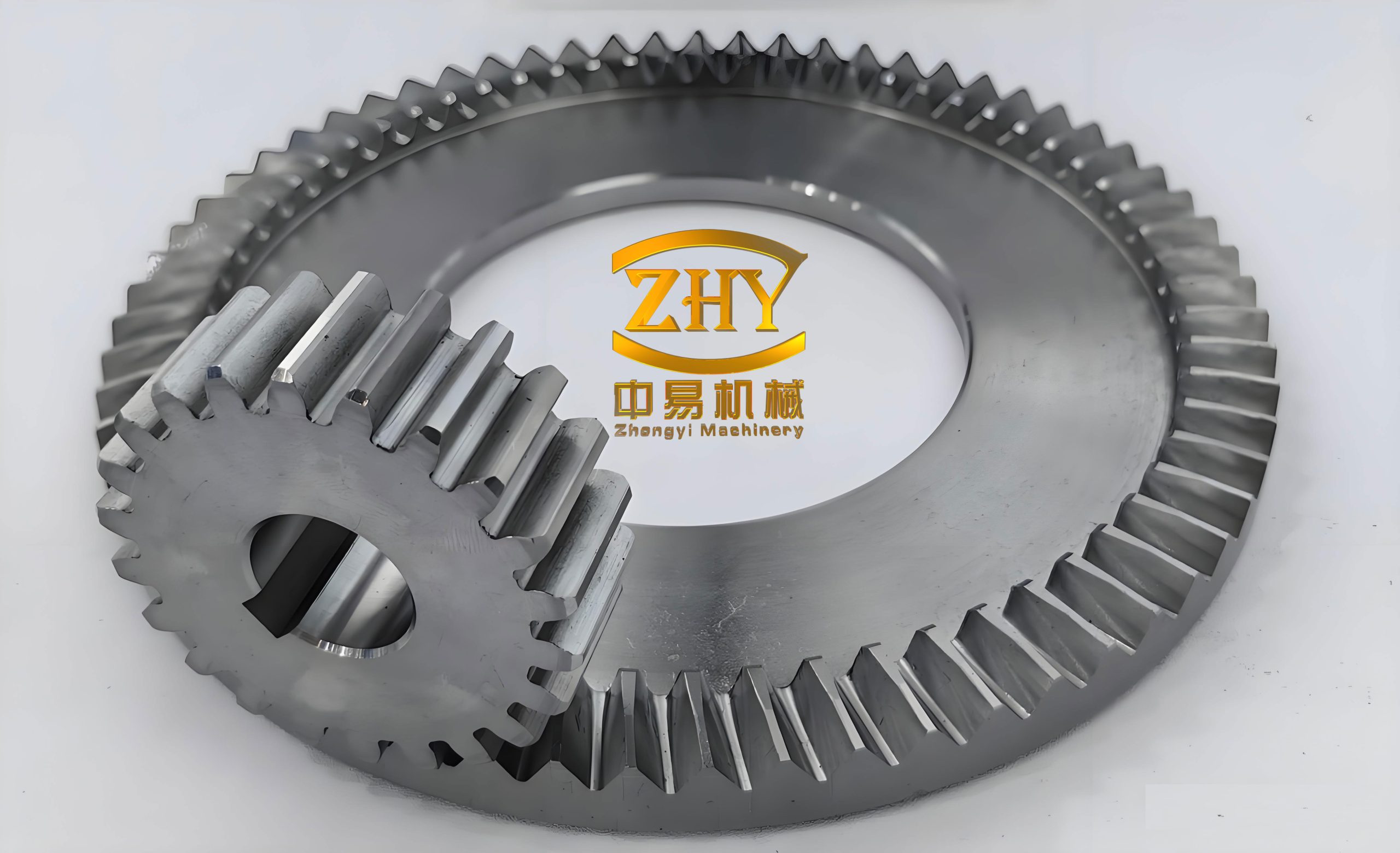
The first Ni45 layer had a relatively smooth surface. The two NiCr-Cr3C2 layers were also well overlapped, although some black oxide appeared on the surface. The oxide formed because the complex geometry of the face gears made heat dissipation more difficult than on flat coupons. The higher surface temperature promoted oxidation. Even so, the layer was continuous and suitable for subsequent grinding.
I measured the thickness of the clad layers at several positions on the tooth surfaces. The results are shown below.
| Position | Ni45 thickness, mm | NiCr-Cr3C2 thickness, mm |
|---|---|---|
| A1 | 0.30 | 0.65 |
| A2 | 0.30 | 0.60 |
| A3 | 0.25 | 0.60 |
| B1 | 0.30 | 0.65 |
| B2 | 0.25 | 0.60 |
| B3 | 0.25 | 0.55 |
| C1 | 0.30 | 0.75 |
| C2 | 0.25 | 0.70 |
| C3 | 0.25 | 0.70 |
| T1 | 0.35 | 0.85 |
| T2 | 0.30 | 0.95 |
| T3 | 0.30 | 0.85 |
The Ni45 thickness ranged from 0.25 mm to 0.35 mm. The cermet thickness on the tooth flanks ranged from 0.55 mm to 0.75 mm, and the thickness on the tooth tip was higher, reaching 0.85–0.95 mm. Some positions were outside the original design range because the inclined tooth surfaces changed the effective spot size and the effective scanning speed. Near the tooth tip, powder interference was weaker, so the layer tended to be thicker. Near the tooth root, powder interference was stronger. At one tooth-tip position, the layer was especially thick because the coating from the outer end overlapped with the coating from the inner end.
The hardness distribution on the face gears is shown below. The transition layer prevented a sudden hardness jump. The hardness increased gradually from the substrate to the surface. The two cermet layers, deposited with slightly different feed rates, produced the intended layer-by-layer hardness increase.
| Position | A1 | A2 | A3 | B1 | B2 | B3 |
|---|---|---|---|---|---|---|
| HV0.2 | 815 | 827 | 715 | 759 | 737 | 720 |
| HRC | 64.4 | 64.9 | 60.6 | 62.4 | 61.7 | 61.0 |
| Position | C1 | C2 | C3 | T1 | T2 | T3 |
|---|---|---|---|---|---|---|
| HV0.2 | 713 | 706 | 698 | 764 | 854 | 827 |
| HRC | 60.8 | 60.3 | 60.0 | 62.6 | 65.7 | 64.9 |
Most positions met the target of HRC 60 or higher. The outer tooth-flank positions were slightly lower, but still close to the target. The tooth-tip positions were higher because the layer was thicker there. Overall, the graded Ni45/NiCr-Cr3C2 structure provided the hardness and toughness combination required for face gears under heavy load.
After laser cladding, the face gears required grinding. The as-clad surface was not accurate enough for meshing. I therefore developed a generating grinding method based on the principle of gear shaping. A dish-shaped grinding wheel replaced the virtual shaper cutter. The grinding wheel rotated about its own axis for the main cutting motion, while the face gear rotated about its own axis. At the same time, the grinding wheel swung about the virtual shaper axis. The generating relationship was
$$\frac{\phi_s}{\phi_f} = \frac{N_f}{N_s}$$
where \(\phi_s\) is the swing angle of the grinding wheel, \(\phi_f\) is the rotation angle of the face gear, \(N_f\) is the number of teeth on the face gear, and \(N_s\) is the number of teeth on the virtual shaper. After one tooth was ground, the face gear was indexed to the next tooth. This continued until all teeth were ground.
To define the grinding wheel profile, I started from the rack cutter and the virtual spur gear. The rack cutter profile can be written as
$$r_j(\mu_j,\theta_j)=
\begin{bmatrix}
l_j \pm \mu_j \sin\gamma_j – \theta_j \cos\gamma_j \\
\mu_j \cos\gamma_j + \theta_j \sin\gamma_j \\
\theta_j \\
1
\end{bmatrix}$$
where \(\gamma_j\) is the rack pressure angle, \(\mu_j\) is the profile parameter, \(\theta_j\) is the axial parameter, and \(l_j\) is the distance from the origin to the rack profile. The normal vector is
$$n_j = \frac{\partial r_j}{\partial \mu_j} \times \frac{\partial r_j}{\partial \theta_j}
=
\begin{bmatrix}
\cos\gamma_j \\
\sin\gamma_j \\
0
\end{bmatrix}$$
The virtual spur gear surface is generated by the rack cutter. In the coordinate system of the virtual gear, the family of rack surfaces and the meshing condition are
$$r_s(\mu_j,\theta_j,\phi_s)=M_{sj}(\phi_s) r_j(\mu_j,\theta_j)$$
$$f_{sj}(\mu_j,\theta_j,\phi_s)=n_j \cdot v_j^{(sj)}=0$$
The transformation matrix can be written as
$$M_{sj}(\phi_s)=
\begin{bmatrix}
\cos\phi_s & \sin\phi_s & 0 & r_{ps}(\sin\phi_s-\phi_s\cos\phi_s) \\
-\sin\phi_s & \cos\phi_s & 0 & r_{ps}(\cos\phi_s+\phi_s\sin\phi_s) \\
0 & 0 & 1 & 0 \\
0 & 0 & 0 & 1
\end{bmatrix}$$
where \(r_{ps}\) is the pitch radius of the virtual spur gear. The virtual gear surface and normal are
$$r_s(\mu_j,\theta_j,\phi_s)=R_s(\mu_j,\theta_j)$$
$$n_s(\phi_s)=L_{sj}(\phi_s)n_j$$
For the grinding wheel, I used the axial section of the virtual gear as the generating profile. Setting the axial coordinate to zero gave the transverse tooth profile. After transforming this profile into the wheel coordinate system, the wheel surface can be expressed as
$$r_h(u_h,\phi_h)=M_{hs}(\phi_h)r_s(u_s)$$
$$n_h(u_h,\phi_h)=L_{hs}(\phi_h)n_s(u_s)$$
The transformation from the virtual gear to the wheel included the center distance \(E_h\) and the wheel rotation angle \(\phi_h\):
$$M_{hs}(\phi_h)=
\begin{bmatrix}
1 & 0 & 0 & 0 \\
0 & \cos\phi_h & -\sin\phi_h & E_h \cos\phi_h \\
0 & \sin\phi_h & \cos\phi_h & E_h \sin\phi_h \\
0 & 0 & 0 & 1
\end{bmatrix}$$
These equations defined the dish-shaped grinding wheel profile for generating the face gears.
I then established the CNC grinding kinematics. The machine had five controlled axes: X and Y translation of the spindle, C rotation of the spindle, B swing of the spindle, and Z translation plus A rotation of the worktable. The coordinate transformations were
$$M_{a1b}(\phi_s)=
\begin{bmatrix}
\cos f_s & 0 & -\sin f_s & 0 \\
0 & 1 & 0 & 0 \\
\sin f_s & 0 & \cos f_s & 0 \\
0 & 0 & 0 & 1
\end{bmatrix}$$
$$M_{na}(A_x,A_z)=
\begin{bmatrix}
1 & 0 & 0 & A_x \\
0 & 1 & 0 & 0 \\
0 & 0 & 1 & A_z \\
0 & 0 & 0 & 1
\end{bmatrix}$$
$$M_{fn}(\phi_f)=
\begin{bmatrix}
\cos\phi_f & \sin\phi_f & 0 & 0 \\
-\sin\phi_f & \cos\phi_f & 0 & 0 \\
0 & 0 & 1 & 0 \\
0 & 0 & 0 & 1
\end{bmatrix}$$
The overall transformation from the grinding wheel to the face gear was
$$M_{fh}(A_x,A_y,A_z,\phi_f,\phi_s)=M_{fn}(\phi_f)M_{na}(A_x,A_z)M_{a1b}(\phi_s)M_{b1h}(A_y)$$
The generated face gear surface vector equation was therefore
$$R_f(\phi_f,\phi_s)=M_{fh}(A_x,A_y,A_z,\phi_f,\phi_s)R_h$$
This equation was used to calculate the tool positions for each grinding pass. The machine interpolated the five axes to produce the generating motion. I used the tooth root as the alignment datum because the root region was flatter and more reliable than the tooth tip after cladding.
For grinding the cermet layer, I selected green silicon carbide as the abrasive because it is hard, sharp, and suitable for hard alloys and ceramics. I used a ceramic bond for rough grinding and a resin bond for finish grinding. The ceramic bond has high hardness, good heat resistance, and good form retention. The resin bond has better toughness and can reduce surface damage during finishing. The wheel specifications are summarized below.
| Abrasive | Bond | Grain size | Wheel width, mm | Wheel diameter, mm | Shape | Axial profile |
|---|---|---|---|---|---|---|
| Green SiC | Ceramic | 90# | 22 | 200 | Dish | Involute |
| Green SiC | Resin | 150# | 22 | 200 | Dish | Involute |
I dressed the wheels with a diamond roller using a single-point rolling method. The dressing parameters are shown below.
| Wheel speed, r/min | Diamond roller speed, r/min | Roller diameter, mm | Table feed, mm/min | Infeed, mm | Passes |
|---|---|---|---|---|---|
| 3000 | 2500 | 100 | 5 | 0.05 | 2 |
The grinding process used a rough grinding step and a finish grinding step. The parameters are listed below.
| Step | Depth of cut, mm | Wheel speed, m/s | Axial feed, mm/min | Radial feed, mm/min |
|---|---|---|---|---|
| Rough grinding | 0.05 | 30 | 0.3 | 4 |
| Finish grinding | 0.015 | 30 | 0.3 | 4 |
I ground the clad face gears on a five-axis CNC face gear grinding machine. The machine used a closed-loop servo control system. I aligned each tooth before grinding to avoid the accumulation of indexing errors and backlash. The ceramic-bond wheel removed the bulk of the excess cermet layer, and the resin-bond wheel improved the surface finish. The grinding process was successful in restoring the tooth profile, although the surface finish still had room for improvement.
After grinding, I measured the tooth surface deviation with a coordinate measuring machine. I defined the tooth tip surface as the datum and the inner bore center as the coordinate origin. I selected a measurement region 21 mm along the tooth width and 7 mm along the tooth height. I used 45 sampling points, 9 along the width and 5 along the height. The measured maximum tooth surface error was 49.7 μm. This value satisfies the meshing accuracy requirement for the face gears in my application. The result confirmed that the combination of laser cladding, gradient design, and generating grinding can produce strengthened face gears with acceptable accuracy.
In summary, I developed a complete route for strengthening and finishing face gears. I used Ni45 as a transition layer and NiCr-Cr3C2 as a hard cermet layer. I optimized the laser power, scanning speed, powder feed rate, overlap ratio, and number of layers. I designed a graded coating for face gears, selected a root-to-tip bidirectional scanning path, and compensated for tooth interference by rotating the laser head. I then ground the clad face gears with green silicon carbide wheels and measured the final tooth surface error. The resulting face gears had a hard, wear-resistant surface, a tough transition layer, and acceptable geometric accuracy. This route is promising for face gears used in high-speed and heavy-load transmissions.
The main quantitative findings can be summarized as follows. The substrate hardness was about HV0.2 270. The NiCr-Cr3C2 surface hardness reached about HV0.2 765, with an average near HV0.2 710, which is roughly three times the substrate hardness. The wear rate of the coating was lower than that of the substrate at both 100 °C and 300 °C. The maximum tooth surface error after grinding was 49.7 μm. These values indicate that the graded laser-clad coating improved the surface performance of the face gears while the grinding process restored the required geometry.
For future work, I believe that small-module face gears deserve more attention. Their tooth spaces are narrow, so the powder stream and laser beam are more easily blocked. A pre-placed powder method may help solve this problem. I also believe that high-precision cladding equipment should be developed for mass production of face gears. With better motion accuracy, real-time monitoring, and closed-loop control, the laser cladding and grinding of face gears can become more efficient and more repeatable. My results provide a basis for further development of face gears with graded cermet coatings for heavy-duty applications.