
I have dedicated my research to the analysis of mesh characteristics for hypoid bevel gears manufactured by the face-hobbed method. Hypoid bevel gears are widely used in automotive, aerospace, and industrial transmissions because of their high contact ratio, strong misalignment tolerance, and suitability for offset crossed-axis arrangements. Unlike face-milled hypoid bevel gears, which have tapering teeth, face-hobbed hypoid bevel gears have uniform depth, meaning that the tooth height remains constant along the face width. This feature improves load distribution and simplifies the cutting process. However, the continuous indexing cutting and the full-generation method make the tooth surface geometry extremely complex. The tooth surface is a non-developable ruled surface generated by a cycloidal path. As a result, accurate modeling, tool error control, and misalignment analysis are critical for achieving low noise and high durability in hypoid bevel gears.
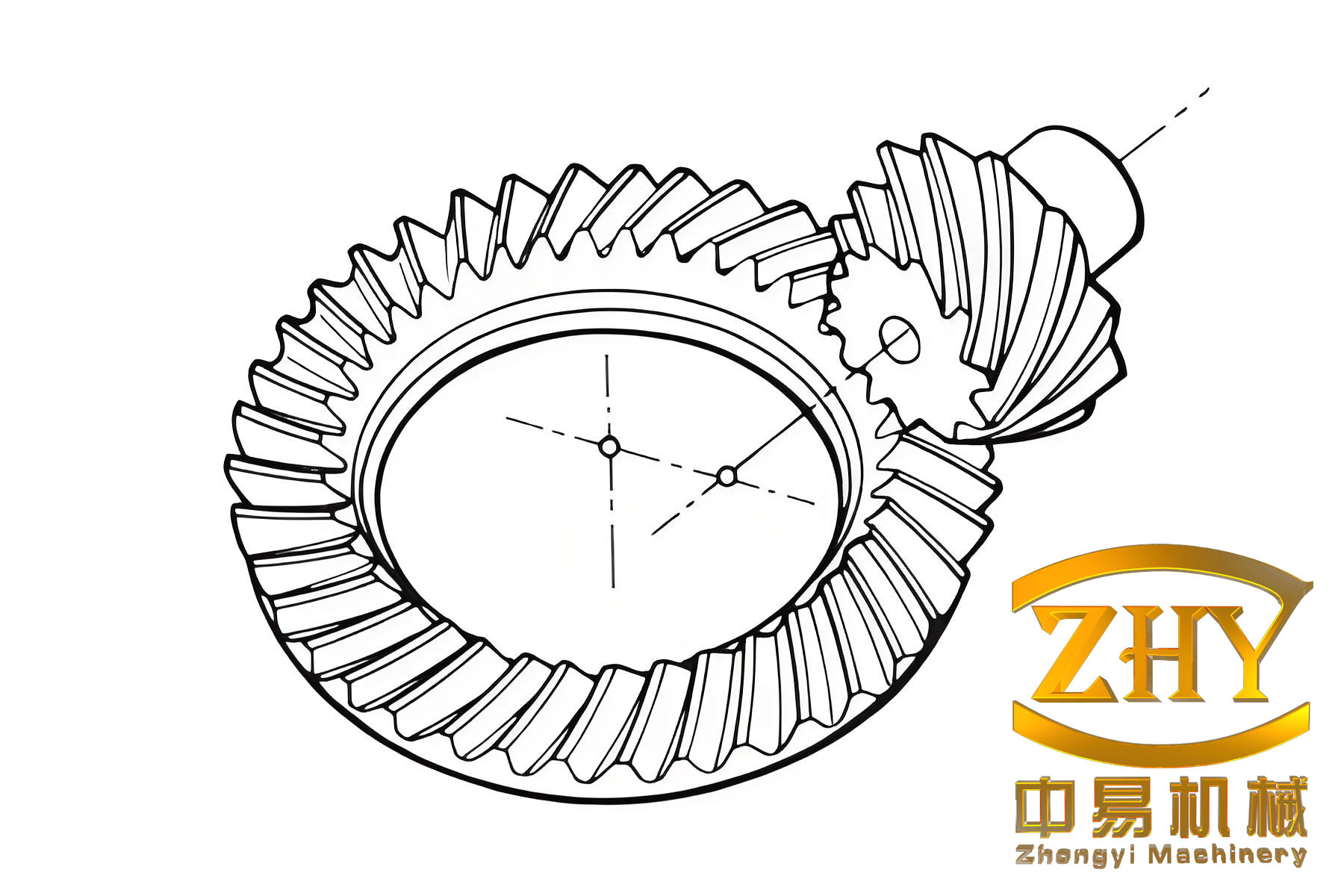
In this work, I first established a mathematical model of the face-hobbed hypoid bevel gear based on the neutral data (ND) normal reference of a three-face cutter head. Then I derived the machine tool coordinate system and the meshing equation. Using these models, I investigated the influence of tool errors on tooth surface geometry. Next, I built a whole-axle mechanical model in MASTA and a finite element loaded contact analysis model for the hypoid bevel gear pair. I calculated the misalignment under theoretical and preset eccentricity conditions and analyzed the effect of misalignment on mesh characteristics. Finally, I performed cutting experiments, tooth surface measurement, and rolling tests to verify my models. The following sections present the detailed methodology, equations, tables, and results.
Geometric Modeling of Face-Hobbed Hypoid Bevel Gears
The face-hobbed process is a continuous indexing cutting method. The cutter head rotates about its own axis while also revolving around the machine cradle axis, generating an extended epicycloid. The cutter head contains several groups of blades. Each group has at least one inner blade and one outer blade, which cut the convex and concave flanks respectively. For uniform-depth hypoid bevel gears, the gear is usually cut by the formate method, while the pinion is cut by the generate method. I used the tilt half-generate method, also known as the Spirac method, because it provides high design and manufacturing efficiency and is suitable when the gear ratio is greater than or equal to three or when the gear pitch angle is greater than sixty degrees.
The cutting edge of a three-face cutter head consists of a main cutting edge and a tip arc. The main cutting edge is usually a circular arc, and the tip arc connects smoothly to the main edge at point M. I established the cutter blade coordinate system on the rake face. The position vector of any point on the main cutting edge in the reference point coordinate system is expressed as:
$$ \mathbf{r}_{b} = \begin{bmatrix} x_{b} \\ y_{b} \\ z_{b} \end{bmatrix} = \begin{bmatrix} r_{c} \sin u \\ r_{c} (1 – \cos u) \\ 0 \end{bmatrix} $$
where \( r_{c} \) is the radius of the main cutting edge, and \( u \) is the arc length parameter from the reference point. For the tip arc, the position vector is:
$$ \mathbf{r}_{t} = \begin{bmatrix} x_{t} \\ y_{t} \\ z_{t} \end{bmatrix} = \begin{bmatrix} r_{t} \sin \phi \\ r_{t} (1 – \cos \phi) \\ 0 \end{bmatrix} $$
where \( r_{t} \) is the tip radius and \( \phi \) is the angular parameter. The complete cutting edge is then transformed from the rake face to the ND normal reference plane using rotation matrices for rake angle, regrind angle, and relief angle. I defined the tool errors with respect to this ND reference, which includes five parameters: main cutting edge radius error \( \Delta r_{c} \), reference point pressure angle error \( \Delta \alpha \), rake angle error \( \Delta \gamma \), regrind angle error \( \Delta \varepsilon \), and cutting side relief angle error \( \Delta \beta \). These errors directly alter the tooth surface geometry of the hypoid bevel gears.
The cutter head coordinate system is attached to the blade group. The transformation from the blade to the cutter head involves the mounting angle and the radius of the reference point. The machine tool coordinate system includes the cradle, the workpiece, and the tool. The tilt angle \( i \) and swivel angle \( j \) control the contact area. The relative position between the cutter head and the workpiece is described by the vertical offset \( E \), the machine root angle \( \gamma \), the bed position correction \( B \), and the horizontal correction \( A \). The complete transformation from the cutter blade to the workpiece blank is:
$$ \mathbf{r}_{w} = M_{w,c} \mathbf{r}_{c} $$
where \( \mathbf{r}_{c} \) is the cutter blade vector in the cutter head system, and \( M_{w,c} \) is the transformation matrix from the cutter head to the workpiece. For the generated pinion, the meshing equation is:
$$ \mathbf{n} \cdot \mathbf{v}^{(cw)} = 0 $$
where \( \mathbf{n} \) is the unit normal vector of the cutter surface, and \( \mathbf{v}^{(cw)} \) is the relative velocity between the cutter and the workpiece. Solving this equation gives the parameter \( u \) for each contact point, and substituting back yields the tooth surface point set. I programmed this procedure in MATLAB and imported the resulting point sets into CREO to build the solid models of the pinion and gear. The assembly model showed no interference at either the toe or the heel, which confirmed the correctness of the mathematical model.
For the formate gear, the tooth surface is directly the cutter surface. For the generate pinion, the tooth surface is the envelope of the cutter surface family. The relative velocity is computed from the machine tool kinematics:
$$ \mathbf{v}^{(cw)} = \mathbf{v}^{(c)} – \mathbf{v}^{(w)} + \boldsymbol{\omega}^{(cw)} \times \mathbf{r}^{(cw)} $$
where \( \mathbf{v}^{(c)} \) and \( \mathbf{v}^{(w)} \) are the translational velocities of the cutter and workpiece, and \( \boldsymbol{\omega}^{(cw)} \) is the relative angular velocity. The meshing equation is solved iteratively for each cutter position. The resulting point set is then used to construct the solid model. The gear parameters and machine settings for the hypoid bevel gears used in this study are listed in Table 1 and Table 2.
| Parameter | Pinion | Gear |
|---|---|---|
| Number of teeth | 11 | 47 |
| Offset (mm) | 38.1 | 38.1 |
| Shaft angle (deg) | 90 | 90 |
| Hand of spiral | Left | Right |
| Modification coefficient | 0.65 | -0.65 |
| Reference point radius (mm) | 76 | 76 |
| Cutting edge radius (mm) concave | 1093.65 | 1360.74 |
| Cutting edge radius (mm) convex | 1062.73 | 1276.45 |
| Pressure angle (deg) concave | 22.3059 | 18.9931 |
| Pressure angle (deg) convex | 20.1933 | 23.5060 |
| Regrind angle (deg) concave | 4.3674 | 5.0309 |
| Regrind angle (deg) convex | 4.7856 | 4.1101 |
| Relief angle (deg) concave | 13.3885 | 13.3823 |
| Relief angle (deg) convex | 12.6729 | 12.6781 |
| Rake angle (deg) concave | 9.5870 | 12.6781 |
| Rake angle (deg) convex | 10.3059 | 9.6107 |
| Parameter | Symbol | Pinion | Gear |
|---|---|---|---|
| Tilt angle (deg) | i | 3.3325 | 0 |
| Swivel angle (deg) | j | 146.9405 | 0 |
| Radial distance (mm) | – | 121.9391 | 122.009 |
| Initial cradle angle (deg) | q | 52.6673 | -29.7048 |
| Vertical offset (mm) | E | 39.8352 | 0 |
| Bed position (mm) | B | -12.2486 | 0 |
| Horizontal position (mm) | A | 3.1158 | 13.9199 |
| Machine root angle (deg) | γ | 23.4453 | 64.7995 |
| Roll ratio | igp | 4.722168 | 0 |
Tool Errors and Their Influence on Tooth Surface Geometry
I defined the tooth surface geometric deviation as the normal distance between the actual tooth surface and the theoretical tooth surface. A positive deviation means the actual surface lies outside the theoretical surface, while a negative deviation means it lies inside. I took the pinion concave flank as the error surface and the convex flank as the standard surface. The tool parameters for the standard case and the error cases are listed in Table 3 and Table 4. The cutting edge radius error was set to -100, -50, +50, and +100 mm. The angle errors were set to -1, -0.5, +0.5, and +1 degree.
| Parameter | Standard | (a) | (b) | (c) | (d) |
|---|---|---|---|---|---|
| Cutting edge radius (mm) | 1062.73 | -100 | -50 | +50 | +100 |
| Parameter | Standard | (a) | (b) | (c) | (d) |
|---|---|---|---|---|---|
| Pressure angle (deg) | 20.1933 | -1 | -0.5 | 0.5 | 1 |
| Regrind angle (deg) | 4.7856 | -1 | -0.5 | 0.5 | 1 |
| Rake angle (deg) | 10.3059 | -1 | -0.5 | 0.5 | 1 |
| Cutting side relief angle (deg) | 12.6729 | -1 | -0.5 | 0.5 | 1 |
For the cutting edge radius error, I found that the tooth surface deviation is negative when the radius error is negative and positive when the radius error is positive. The deviation is larger at the heel than at the toe. The maximum deviation occurs near the heel and top, while the minimum occurs near the toe and middle. The influence of the cutting edge radius on the geometric deviation is not very significant. The maximum deviation difference between the positive and negative errors is about 0.0023 mm for a 100 mm change in radius. Therefore, the spheric radius error has only a minor effect on the tooth surface geometry of hypoid bevel gears.
For the reference point pressure angle error, the tooth surface deviation pattern is similar: larger at the heel, smaller at the toe, and larger at the top and root than in the middle. A positive pressure angle error produces a negative deviation, while a negative error produces a positive deviation. When the pressure angle error changes from \( -1^\circ \) to \( +1^\circ \), the maximum deviation reaches 0.2303 mm and the minimum is 0.0025 mm. The deviation increases as the pressure angle error increases, and the positive error has a greater effect than the negative error. This indicates that the reference point pressure angle is a critical parameter for controlling the tooth surface geometry of hypoid bevel gears.
For the regrind angle error, the deviation pattern is again similar to the pressure angle case. A negative regrind angle error gives a positive deviation, and a positive error gives a negative deviation. The maximum deviation is 0.0312 mm and the minimum is 0.0000654 mm. The deviation increases almost linearly with the regrind angle error. For the rake angle error, the deviation pattern is the same, but the magnitude is extremely small. The maximum deviation is only about 0.000012 mm, which means the rake angle has almost no effect on the tooth surface geometry. For the cutting side relief angle error, the deviation pattern is also similar. A negative relief angle error gives a positive deviation, and a positive error gives a negative deviation. The maximum deviation is 0.0056 mm and the minimum is 0.0001 mm. The deviation increases with the relief angle error.
I summarized the maximum deviations for all five tool errors in Table 5. The ranking of influence from strongest to weakest is: reference point pressure angle, cutting side relief angle, regrind angle, rake angle, and cutting edge radius. The cutting edge radius has the least effect. The rake angle has a very small effect on the geometric deviation but may still affect surface roughness.
| Tool error | Maximum deviation (mm) for +1° or +100 mm | Maximum deviation (mm) for -1° or -100 mm | Ranking |
|---|---|---|---|
| Cutting edge radius | 0.0023 | 0.0023 | 5 |
| Reference point pressure angle | 0.2303 | 0.2303 | 1 |
| Regrind angle | 0.0312 | 0.0312 | 3 |
| Rake angle | 0.000012 | 0.000012 | 4 |
| Cutting side relief angle | 0.0056 | 0.0056 | 2 |
Whole-Axle Mechanical Model and Misalignment Analysis
To study the actual meshing behavior of hypoid bevel gears in a vehicle axle, I built a whole-axle mechanical model using MASTA software. The model includes the housing, input pinion shaft, gear, differential assembly, left and right output half-shafts, hub bearings, and other components. The power flow is from the input pinion shaft to the gear, then to the differential housing, sun gears, output half-shafts, and finally to the hubs. The input pinion shaft is supported by two tapered roller bearings arranged in a back-to-back configuration, which effectively handles the axial forces generated by the hypoid bevel gears. The differential assembly includes the gear, differential case, planet gears, and side gears. I used conceptual bearings to represent the internal supports, with stiffness values listed in Table 6.
| Bearing | Axial stiffness (N/m) | Radial stiffness (N/m) | Tilt stiffness (N/m) |
|---|---|---|---|
| Support 1 | 0 | 1e6 | 1e6 |
| Support 2 | 1e9 | 1e4 | 1e6 |
| Support 3 | 1e9 | 1e9 | 1e6 |
| Support 4 | 0 | 1e9 | 1e6 |
| Support 5 | 1e9 | 1e9 | 1e6 |
For the hypoid bevel gears, I imported the tooth surface model from KIMOS into MASTA. The misalignment of the hypoid bevel gears is defined by four components: offset error \( \Delta E \), pinion axial displacement \( \Delta X_{P} \), gear axial displacement \( \Delta X_{W} \), and shaft angle error \( \Delta \Sigma \). The offset error is positive when the offset decreases. The pinion axial displacement is positive from toe to heel. The gear axial displacement is positive from toe to heel. The shaft angle error is positive when the angle increases. I considered three load cases: 50 N·m at 6000 rpm, 450 N·m at 680 rpm, and 900 N·m at 330 rpm. For each load case, I calculated the theoretical misalignment without any preset box eccentricity and the preset misalignment with box eccentricity. The preset box eccentricity was 1.12 mm in the A direction and 1 mm in the B direction. The results are shown in Table 7 and Table 8.
| Component | 50 N·m | 450 N·m | 900 N·m |
|---|---|---|---|
| Gear ΔE (mm) | 0.6469 | 2.6167 | 4.1776 |
| Gear ΔXP (mm) | -4.238 | -22.4117 | -38.981 |
| Gear ΔXW (mm) | 7.6618 | 32.5358 | 52.1534 |
| Gear ΔΣ (deg) | 0.02224 | 0.1053 | 0.1759 |
| Pinion ΔE (mm) | 12.7469 | 71.9841 | 128.2177 |
| Pinion ΔXP (mm) | -8.1972 | -42.5919 | -74.0569 |
| Pinion ΔXW (mm) | 13.4506 | 81.1147 | 146.95 |
| Pinion ΔΣ (deg) | -0.08085 | -0.5288 | -0.9765 |
| Total ΔE (mm) | 13.3938 | 74.6008 | 132.3953 |
| Total ΔXP (mm) | -12.4352 | -65.0036 | -113.0379 |
| Total ΔXW (mm) | 21.1124 | 113.6506 | 199.1034 |
| Total ΔΣ (deg) | -0.0586 | -0.4235 | -0.8006 |
| Component | 50 N·m | 450 N·m | 900 N·m |
|---|---|---|---|
| Gear ΔE (mm) | 0.5946 | 2.1223 | 3.183 |
| Gear ΔXP (mm) | -3.8788 | -19.0303 | -32.1943 |
| Gear ΔXW (mm) | 7.6099 | 32.0996 | 51.288 |
| Gear ΔΣ (deg) | 0.02261 | 0.1085 | 0.1821 |
| Pinion ΔE (mm) | 12.1634 | 66.8763 | 118.0536 |
| Pinion ΔXP (mm) | -7.3678 | -35.495 | -60.1514 |
| Pinion ΔXW (mm) | 13.7522 | 83.9604 | 152.5045 |
| Pinion ΔΣ (deg) | -0.08237 | -0.5437 | -1.0056 |
| Total ΔE (mm) | 12.758 | 68.9985 | 121.2366 |
| Total ΔXP (mm) | -11.2466 | -54.5253 | -92.3457 |
| Total ΔXW (mm) | 21.3621 | 116.06 | 203.7924 |
| Total ΔΣ (deg) | -0.05977 | -0.4352 | -0.8236 |
From these tables, I observed that the misalignment increases with load in all four directions. The pinion misalignment is the dominant contribution to the total misalignment, especially for the offset error. The preset box eccentricity reduces the offset error and the pinion axial displacement significantly. The gear axial displacement slightly increases under high load, but the gear axial direction is less sensitive to misalignment. Therefore, the preset box eccentricity is beneficial for reducing the misalignment of hypoid bevel gears and improving the mesh quality.
Loaded Contact Analysis and Mesh Characteristics
I established a finite element loaded contact analysis model for the hypoid bevel gears. The pinion used a full-tooth model, and the gear used a partial-tooth model with eleven teeth. The contact pairs were set between the pinion concave flank and the gear convex flank, with a frictionless hard contact formulation. The material was homogeneous quenched and tempered steel with a Young’s modulus of 210 GPa and a Poisson’s ratio of 0.3. I used three analysis steps: first, a small rotation of the pinion to establish contact; second, applying a torque on the gear reference point; third, rotating the pinion to drive the gear. The pinion mesh used tetrahedral elements (C3D10), and the gear mesh used hexahedral elements (C3D8R).
For the standard installation with no misalignment, the contact pattern and transmission error under different loads are shown in Table 9. The contact pattern is located near the heel and top of the tooth. At 50 N·m, the contact is nearly a point contact with a maximum contact stress of 403 MPa and an area ratio of 11.78%. At 900 N·m, the contact becomes elliptical with a maximum stress of 1294 MPa and an area ratio of 40.5%. The transmission error peak-to-peak value increases with load.
| Load (N·m) | Max contact stress (MPa) | Area ratio (%) | TE peak-to-peak (μm) | Max root bending stress (MPa) |
|---|---|---|---|---|
| 50 | 403 | 11.78 | 0.08 | 29.61 |
| 450 | 950 | 30.7 | 0.188 | 202.7 |
| 900 | 1294 | 40.5 | 0.35 | 321.67 |
Under theoretical misalignment, the contact pattern at the tooth top shows edge contact, and this becomes more pronounced as the load increases. The maximum contact stress slightly increases, and the contact area slightly decreases compared with the standard installation. The transmission error peak-to-peak values are larger than the standard values. Under preset eccentricity, the contact pattern is similar to the theoretical misalignment case, but the transmission error peak-to-peak value is slightly lower. The comparison is summarized in Table 10.
| Load (N·m) | Standard (μm) | Theoretical misalignment (μm) | Preset eccentricity (μm) |
|---|---|---|---|
| 50 | 0.08 | 0.12 | 0.11 |
| 450 | 0.188 | 0.25 | 0.23 |
| 900 | 0.35 | 0.48 | 0.45 |
Influence of Tool Errors on Mesh Characteristics
I also investigated how the five tool errors affect the mesh characteristics of the hypoid bevel gears under a standard load of 450 N·m. The results are summarized below and in Table 11.
For the cutting edge radius error, the contact pattern location and size are almost unchanged. The transmission error mean value increases slightly as the radius decreases. The peak-to-peak value varies between 0.18 and 0.225 μm. The root bending stress location is unchanged. Therefore, the cutting edge radius has a minor effect on mesh characteristics.
For the reference point pressure angle error, the contact pattern moves from the heel and root toward the toe and top as the pressure angle increases. The contact pattern size first increases and then decreases. The transmission error mean value decreases with increasing pressure angle error. The peak-to-peak value increases significantly: a +1° error increases the peak-to-peak value by 276%, while a -1° error decreases it by 56%. The root bending stress first decreases and then increases, reaching a minimum of 152.86 MPa at a certain error. This shows that the pressure angle is a highly sensitive parameter.
For the rake angle error, the contact pattern is almost unaffected. The transmission error mean value increases slightly from 11.28 to 11.33 μm as the rake angle error changes from -1° to +1°. The peak-to-peak value increases by about 9.8%. The root bending stress is also nearly unchanged. Therefore, the rake angle has a small effect on mesh characteristics.
For the regrind angle error, the contact pattern moves toward the tooth top as the regrind angle increases. The contact area decreases from 33.4% to 28.8%. At a +1° error, edge contact begins to appear at the tooth top. The transmission error peak-to-peak value increases with positive regrind angle error but remains almost unchanged for negative errors. The root bending stress location is unchanged, but the magnitude decreases slightly with reduced regrind angle. Thus, reducing the regrind angle can improve the contact characteristics.
For the cutting side relief angle error, the contact pattern location and size are almost unchanged. The transmission error mean value increases significantly from 11.21 to 11.42 μm as the relief angle error changes from -1° to +1°. The peak-to-peak value increases by about 9.54%. The root bending stress decreases slightly with reduced relief angle. The influence of the relief angle is similar to that of the rake angle, but the relief angle has a greater effect on the transmission error mean value.
| Tool error | Contact pattern | Transmission error mean | Transmission error peak-to-peak | Root bending stress |
|---|---|---|---|---|
| Cutting edge radius | Minor | Slight increase with decreasing radius | 0.18–0.225 μm | Minor |
| Pressure angle | Strong shift from heel-root to toe-top | Decreases with increasing error | +276% for +1°, -56% for -1° | Minimum at certain error |
| Rake angle | Almost none | +0.05 μm | +9.8% | Almost none |
| Regrind angle | Shift toward top, area decreases | Slight increase | Increases with positive error | Decreases with reduced angle |
| Relief angle | Almost none | +0.21 μm | +9.54% | Decreases with reduced angle |
Experimental Verification
To verify my mathematical model and mesh analysis, I performed cutting experiments on a C27 CNC machine using the gear and machine parameters listed in Table 1 and Table 2. The hypoid bevel gears were then installed in a vehicle rear axle housing. I measured the tooth surfaces using a Gleason 650GMS gear measuring machine. The measured theoretical tooth surface point sets were compared with my mathematical model. The maximum deviation for the pinion concave flank was 0.0075 mm at the toe and top, and the minimum deviation was -0.0015 mm at the heel and root. For the gear convex flank, the maximum deviation was 0.0023 mm at the toe and top, and the minimum was -0.0005 mm at the heel and root. These small deviations confirm the accuracy of my tooth surface mathematical model.
After heat treatment and lapping, I conducted rolling tests on a Klingenberg rolling tester. The actual contact pattern moved from the heel toward the toe after heat treatment, which meets the design requirement of moving the contact pattern to the middle of the tooth surface. The contact area remained almost unchanged. I also compared the finite element results with the KIMOS theoretical TCA and LTCA results. The contact pattern location and size from my finite element model agreed well with the KIMOS results. The transmission error from my finite element model was closer to the measured transmission error from the rolling test than the theoretical TCA result. This further verifies the correctness of my tooth surface model and mesh analysis.
Conclusions
In this research, I established a precise mathematical model for face-hobbed hypoid bevel gears based on the ND normal reference of a three-face cutter head. I derived the machine tool coordinate transformations and the meshing equation for both the formate gear and the generate pinion. I proposed a complete modeling workflow and built solid models of the hypoid bevel gears. I investigated the influence of tool errors on tooth surface geometry and found that the reference point pressure angle has the strongest effect, followed by the cutting side relief angle and regrind angle, while the cutting edge radius and rake angle have minor effects.
I built a whole-axle mechanical model in MASTA and a finite element loaded contact analysis model for the hypoid bevel gears. I calculated the misalignment under theoretical and preset eccentricity conditions and found that the preset box eccentricity reduces the offset error and pinion axial displacement, which improves the mesh quality. The misalignment increases with load, and the pinion misalignment dominates the total misalignment.
I analyzed the mesh characteristics under different misalignment conditions and tool errors. The contact pattern shifts and edge contact appears under misalignment, and the transmission error increases. The preset eccentricity slightly reduces the transmission error peak-to-peak value. The reference point pressure angle and regrind angle significantly affect the contact pattern and transmission error, while the rake angle and relief angle mainly affect the transmission error mean value. The cutting edge radius has a minor effect on mesh characteristics.
Finally, I performed cutting experiments, tooth surface measurement, and rolling tests. The comparison between the theoretical and measured tooth surfaces confirmed the accuracy of my mathematical model. The comparison of the contact pattern and transmission error among the finite element model, KIMOS, and rolling tests further validated the correctness of my mesh analysis. These results provide a useful reference for optimizing cutter design and improving the mesh quality of face-hobbed hypoid bevel gears.