
When I work on a hypoid pinion for an automotive rear axle, I treat the forged gear blank as the foundation of the entire main reducer assembly. The hypoid gear is not merely a rotating component; it is a safety-critical part. During vehicle operation it must carry different torque levels, different rotational speeds, the mass of the body, the mass of the payload, and a wide spectrum of alternating stresses caused by changing road conditions. Because of this, the quality of the forged gear blank has a direct influence on vehicle safety. In many designs the pinion of a hypoid gear set is made as one piece with a shank or shaft. A shaft-type pinion is a common design for a drive gear in a rear axle. The production of such a forged gear blank is highly specialized in high-volume automotive manufacturing, and the blank is generally produced as a die forging. In my process development work, however, I have found that traditional die forging alone is no longer sufficient for near-net-shape requirements. Cross rolling, warm extrusion, hot extrusion, die forging, and precision forming have all been studied, but many routes still suffer from low material utilization, too many forming operations, or high cost. Therefore, I prefer a hot extrusion route for the forged gear blank because it gives a favorable balance between shape, properties, and productivity.
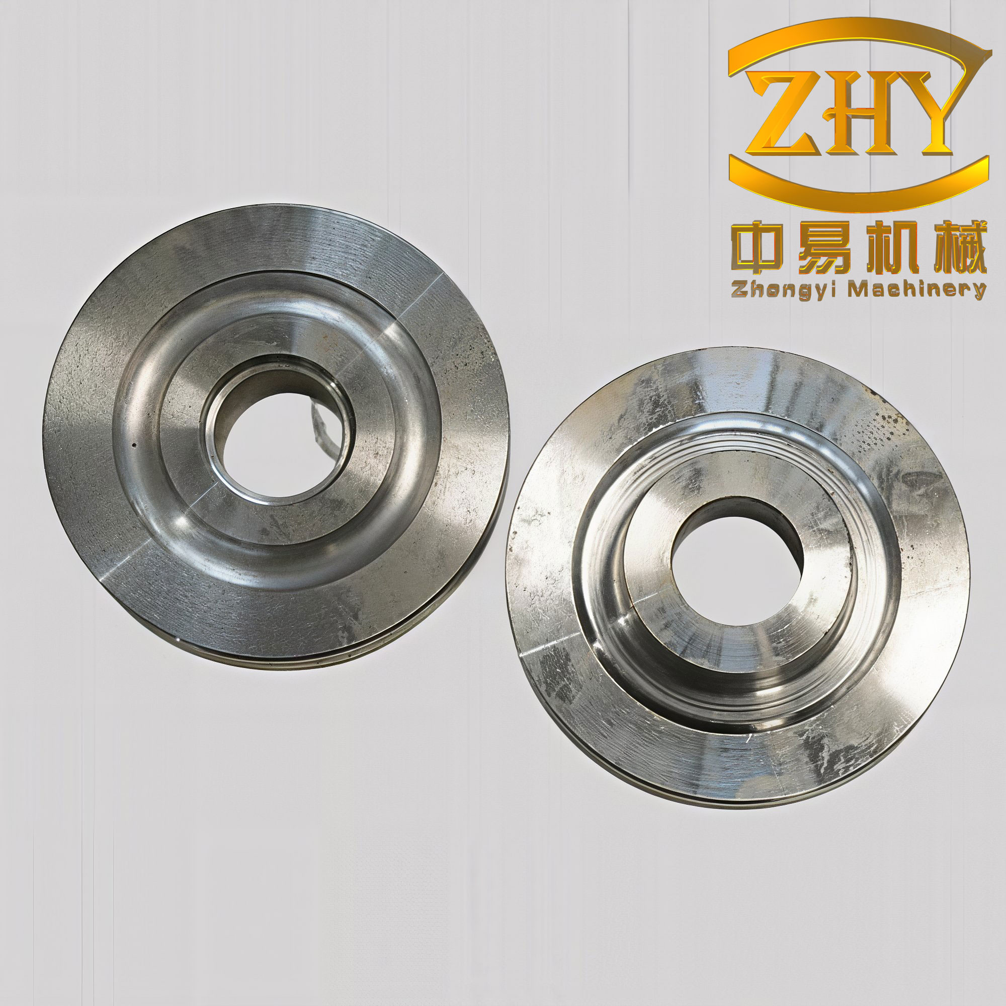
In my first-person view of the shop floor, the hot extrusion process for a forged gear blank begins with a clear definition of the required geometry. I calculate the billet volume from the final forged gear blank volume plus scale loss and limited process loss. In a closed-die hot extrusion operation there is usually no flash, so the volume relationship is tighter than in conventional impression die forging. I write the basic volume balance as
$$V_b = V_f + V_{scale} + V_{loss}$$
where \(V_b\) is the billet volume, \(V_f\) is the forged gear blank volume after cooling, \(V_{scale}\) is the volume lost to oxidation, and \(V_{loss}\) is a small allowance for incomplete filling or trimming. The corresponding billet mass is
$$m_b = \rho V_b$$
with \(\rho\) being the density of the selected steel at room temperature. For a forged gear blank, I do not treat this calculation as a rough estimate. The die cavity is closed, so an oversized billet can overload the press, while an undersized billet can leave the large end or the shank underfilled. Therefore, I combine the volume calculation with a weight check and a temperature-dependent density correction. The density correction can be written as
$$\rho(T) = \rho_0 \left[1 – 3\alpha (T – T_0)\right]$$
where \(\rho_0\) is the density at the reference temperature \(T_0\), \(\alpha\) is the linear thermal expansion coefficient, and \(T\) is the instantaneous temperature. Although this correction is small for steel in the hot working range, it helps me keep the forged gear blank dimensions consistent when the process window shifts.
The main process route I use for a forged gear blank is intentionally short: billet cutting, heating, shank stretching or rod forming, and large-end extrusion. I summarize this route in the following table because it helps the operators and die designers see the purpose of each step.
| Step | Operation | Main Purpose | Key Variables | Output Check |
|---|---|---|---|---|
| 1 | Billet cutting | Provide a precise volume for the forged gear blank | Diameter, length, mass, cut quality | Mass tolerance, end squareness |
| 2 | Heating | Raise the steel into the hot forging range | Temperature, time, atmosphere | Surface scale, core temperature |
| 3 | Shank or rod stretching | Form the shaft-like portion of the forged gear blank | Die gap, ram speed, temperature | Diameter, straightness, length |
| 4 | Large-end extrusion | Fill the gear head and transition zone of the forged gear blank | Ram speed, die closure, lubrication | Fill, concentricity, flow lines |
| 5 | Cooling and inspection | Stabilize the forged gear blank and verify quality | Cooling rate, fixture, measurement plan | Dimensions, hardness, defects |
The heating stage is the first place where I see the hot extrusion process either succeed or fail. I bring the billet into the range of \(1100\) to \(1200^\circ\mathrm{C}\). I write this window as
$$T_h \in \left[1100, 1200\right]^\circ\mathrm{C}$$
Within this range the flow behavior of the steel is favorable, the deformation resistance is lower, and the material can fill the closed cavity of the forged gear blank without excessive press load. However, the temperature is high enough to affect die life. I therefore balance the need for low flow stress against the need for reasonable die service life. The flow stress itself can be represented in a general hot-working form as
$$\sigma_f = C \dot{\varepsilon}^{m} \exp\left(\frac{Q}{RT}\right)$$
where \(\sigma_f\) is the flow stress, \(C\) is a material constant, \(\dot{\varepsilon}\) is the strain rate, \(m\) is the strain-rate sensitivity, \(Q\) is the activation energy for deformation, \(R\) is the universal gas constant, and \(T\) is the absolute temperature. For a more complete description I also include strain hardening or softening through a strain term,
$$\sigma_f = K \varepsilon^{n} \dot{\varepsilon}^{m} \exp\left(\frac{Q}{RT}\right)$$
where \(K\) is a strength coefficient and \(n\) is the strain exponent. In the hot extrusion of a forged gear blank, the strain-rate and temperature terms usually dominate over the strain term because recovery and recrystallization occur during deformation. This is why I focus so heavily on temperature control and ram speed.
| Parameter | Symbol | Preferred Range | Reason |
|---|---|---|---|
| Hot working temperature | \(T_h\) | \(1100\) to \(1200^\circ\mathrm{C}\) | Low flow stress and good cavity filling |
| Minimum forming temperature | \(T_{min}\) | Approximately \(1000^\circ\mathrm{C}\) or as allowed by the alloy | Avoid excessive load and cracking |
| Maximum heating temperature | \(T_{max}\) | Below the overheating or burning limit | Prevent incipient melting and grain growth |
| Die preheat temperature | \(T_d\) | Controlled and stable | Reduce thermal shock and improve flow |
| Contact time | \(t_c\) | As short as practicable | Limit heat loss to the die |
I describe the deformation of the forged gear blank in four linked physical events. First, I heat the material to an appropriate hot forging temperature above the recrystallization temperature, namely \(1100\) to \(1200^\circ\mathrm{C}\). Second, I load the material into the upper die, and the punch starts to extrude the billet into the upper and lower die cavity; the force rises very quickly and reaches its maximum in an instant. Third, I change the station. The upper die moves downward, the height of the deformation zone decreases, and the metal fills the whole upper and lower die region. Fourth, the hot extrusion of the forged gear blank forces the billet, under a three-dimensional and non-uniform compressive stress state, through a die opening or gap. The cross section decreases, and the length increases or the shape shortens in another direction depending on the local constraint. This description is simple, but it contains the essential mechanics that I use when I set the process.
| Stage | Die Motion | Metal Flow Behavior | Force Characteristic | Process Control |
|---|---|---|---|---|
| Initial contact | Punch approaches the billet | Local upsetting begins | Rapid force rise | Alignment and billet placement |
| Confined extrusion | Punch enters the upper die | Material flows into upper and lower cavities | Peak force can occur | Ram speed, lubrication, temperature |
| Station change and closure | Upper die moves downward | Deformation zone height decreases | Force remains high | Die closure and concentricity |
| Final filling | Dies close completely | Metal fills the large end and shank transition | Force stabilizes or rises to final peak | Volume control and die venting |
I use several equations to quantify the hot extrusion of a forged gear blank. The equivalent strain in extrusion is commonly written as
$$\bar{\varepsilon} = \ln\left(\frac{A_0}{A_f}\right)$$
where \(A_0\) is the initial cross-sectional area and \(A_f\) is the final cross-sectional area. For a round section this becomes
$$\bar{\varepsilon} = 2 \ln\left(\frac{D_0}{D_f}\right)$$
where \(D_0\) and \(D_f\) are the initial and final diameters. The extrusion ratio is
$$R = \frac{A_0}{A_f}$$
and the area reduction is
$$r = 1 – \frac{1}{R} = \frac{A_0 – A_f}{A_0}$$
If I express the reduction as a percentage, I write
$$r_{\%} = \left(1 – \frac{A_f}{A_0}\right) \times 100\%$$
The extrusion pressure can be estimated from the flow stress and the die geometry. A useful engineering form is
$$p = \sigma_f \left(\ln R + \frac{2\mu L}{D}\right)$$
where \(p\) is the extrusion pressure, \(\mu\) is the friction coefficient, \(L\) is the contact length, and \(D\) is a characteristic diameter. The corresponding force is
$$F = p A_0$$
If I use the punch area \(A_p\), the force can also be written as
$$F = \sigma_f A_p \left(\ln R + \frac{2\mu L}{D}\right)$$
For a forged gear blank with a complex head and a long shank, I do not rely on a single formula alone. I combine these estimates with finite element analysis and press trials. The reason is that the local strain, temperature, and friction vary strongly from the shank to the large end. I write the peak force condition as
$$F_{max} = \max_{t} F(t)$$
and I compare this value with the press capacity. I also calculate the temperature rise caused by deformation, because it affects flow stress and die life:
$$\Delta T = \frac{\eta \sigma_f \bar{\varepsilon}}{\rho c_p}$$
where \(\eta\) is the fraction of deformation energy converted to heat, \(\rho\) is density, and \(c_p\) is specific heat. In hot extrusion of a forged gear blank, this temperature rise can be beneficial for filling, but it can also cause local overheating if the strain rate is too high.
| Quantity | Formula | Use in Process Design |
|---|---|---|
| Equivalent strain | \(\bar{\varepsilon} = \ln\left(A_0/A_f\right)\) | Estimate deformation severity |
| Extrusion ratio | \(R = A_0/A_f\) | Relate billet and final section |
| Area reduction | \(r = 1 – 1/R\) | Quantify section change |
| Extrusion pressure | \(p = \sigma_f\left(\ln R + 2\mu L/D\right)\) | Estimate die and press load |
| Extrusion force | \(F = p A_0\) | Compare with press capacity |
| Deformation heating | \(\Delta T = \eta \sigma_f \bar{\varepsilon}/(\rho c_p)\) | Check local temperature rise |
| Ram speed | \(v = 40\) to \(60\,\mathrm{mm/s}\) | Control contact time and productivity |
| Contact time | \(t_c = L_s/v\) | Limit heat loss to the die |
I pay close attention to the relationship between extrusion ratio and strain because it determines whether the forged gear blank can be produced in one hot extrusion step or whether I need an intermediate shape. In general, a higher extrusion ratio produces a more refined and denser microstructure, but it also increases the required force and the risk of surface tearing or internal cracking. I therefore set the ratio according to the alloy, the billet temperature, the lubrication condition, and the die design. The following table shows how I think about the effect of increasing extrusion ratio.
| Extrusion Ratio \(R\) | Equivalent Strain \(\bar{\varepsilon}\) | Expected Benefit | Main Risk |
|---|---|---|---|
| Low | Small | Lower force and easier filling | Insufficient grain refinement |
| Moderate | Medium | Good flow-line control and density | Moderate die wear |
| High | Large | Strong refinement and high strength | Higher force, cracking, die overload |
| Very high | Very large | Possible property gain | Surface tearing, adiabatic heating, poor die life |
The hot extrusion of a forged gear blank offers several advantages that I value in production. The first advantage is near-net shape. The forged gear blank has small machining allowance, often only \(0.5\) to \(2.5\,\mathrm{mm}\) per side. The surface quality and dimensional accuracy are high. I typically target a surface roughness of about \(Ra = 3.2\,\mu\mathrm{m}\) and a dimensional tolerance in the range of IT6 to IT7. This reduces machining time and material waste, and it makes the forged gear blank much closer to the final pinion geometry.
The second advantage is lower operator effort and better working conditions. Hot extrusion is performed on a press, so it is easy to mechanize and automate. The press slide can produce one extrusion part in one or two strokes. The operation is convenient, easy to learn, and highly productive. In my experience, this reduces the physical demands on the operator and improves the consistency of the forged gear blank from stroke to stroke.
The third advantage is improved mechanical performance. During hot extrusion the metal is under a three-dimensional, non-uniform compressive stress state. After extrusion, the grain structure of the forged gear blank becomes denser, the metal flow lines are not cut, and the flow lines become continuous along the contour of the extruded part. This raises the strength of the forged gear blank and creates the possibility of replacing a higher-strength steel with a lower-strength steel in some applications. I have seen this effect clearly in the transition zone between the shank and the large end, where continuous flow lines are much more favorable than cut flow lines.
The fourth advantage is fewer operations and a shorter production cycle. The hot extrusion process forms the forged gear blank in a closed die cavity. There is no flash, so there is no trimming operation. This reduces the number of subsequent steps and lowers production cost. When I compare this with a traditional die forging route, the difference in material utilization and operation count is significant.
| Advantage | Quantified Target or Typical Value | Effect on Production |
|---|---|---|
| Near-net shape | Machining allowance \(0.5\) to \(2.5\,\mathrm{mm}\) per side | Less material removal, lower cost |
| Surface quality | \(Ra \approx 3.2\,\mu\mathrm{m}\) | Reduced finishing operations |
| Dimensional accuracy | IT6 to IT7 | Better fit and function |
| Automation | One or two press strokes per part | High productivity and repeatability |
| Mechanical properties | Denser grains, continuous flow lines | Higher strength and fatigue resistance |
| Operation count | No flash and no trimming | Shorter cycle and lower cost |
| Working environment | Press-based forming | Lower labor intensity and cleaner shop floor |
I also use quantitative comparisons to decide whether hot extrusion is the right route for a forged gear blank. A traditional die forging process usually has more flash, more trimming, more heating steps, and more intermediate handling. A hot extrusion process for a forged gear blank can consolidate the shaping of the shank and the large end into a tighter sequence. The table below shows the comparison I use in process reviews.
| Factor | Traditional Die Forging | Hot Extrusion |
|---|---|---|
| Flash | Usually present | Normally absent in closed die |
| Trimming | Required | Not required |
| Material utilization | Often lower | Higher |
| Machining allowance | Larger | Smaller, often \(0.5\) to \(2.5\,\mathrm{mm}\) |
| Flow lines | May be cut at flash | Continuous along contour |
| Operation count | Higher | Lower |
| Mechanical properties | Good but less uniform | Dense, refined, and directional |
| Automation potential | Moderate | High |
Even though the hot extrusion of a forged gear blank has many advantages, I must control several critical issues. The first is the hot extrusion temperature. I keep the billet in the range of \(1100\) to \(1200^\circ\mathrm{C}\). In this range the material has the best flow ability and low deformation resistance, so it is easy to form. However, the high temperature also affects die life. I therefore monitor both the billet temperature and the die temperature. The forming temperature must be controlled before extrusion. As the metal temperature rises, the ultimate strength decreases and the plasticity index increases. The higher the heating temperature, the faster the strength drops. The forming force is proportional to the strength limit. To reduce forming force and energy consumption, I raise the billet temperature as much as possible without causing overheating or burning. This is the initial forging temperature.
The second issue is lubrication. The lubricant must reduce friction between the die and the workpiece and reduce heat transfer from the workpiece to the die. A suitable lubricant lowers deformation resistance, helps the metal fill the die cavity, reduces die wear and fracture risk, prevents rapid cooling of the billet, prevents rapid heating of the die, acts as a thermal insulator, and helps maintain surface roughness and ejection. For hot extrusion of a forged gear blank, I require a lubricant with good thermal insulation, low residue, no oxidation corrosion on the forging or die cavity, and good stability. The friction condition can be represented by
$$\mu = \frac{\tau}{\sigma_n}$$
where \(\mu\) is the friction coefficient, \(\tau\) is the shear stress at the interface, and \(\sigma_n\) is the normal pressure. I also estimate the thermal resistance of the lubricant film through a simplified heat transfer relation,
$$q = h A \left(T_b – T_d\right)$$
where \(q\) is the heat flux, \(h\) is the interface heat transfer coefficient, \(A\) is the contact area, \(T_b\) is the billet temperature, and \(T_d\) is the die temperature. A good lubricant reduces \(h\), which protects the die and keeps the forged gear blank from cooling too quickly.
| Function | Requirement | Effect on the Forged Gear Blank |
|---|---|---|
| Friction reduction | Low and stable friction coefficient | Lower extrusion force and better filling |
| Heat insulation | Low thermal conductivity | Less billet cooling and less die heating |
| Release | Clean ejection without sticking | Better surface quality and dimensional control |
| Residue | Low residue and easy removal | Cleaner forged gear blank surface |
| Corrosion | No oxidation corrosion | Longer die life and fewer surface defects |
| Stability | Stable at elevated temperature | Consistent lubrication during the stroke |
The third issue is die material selection. When I design a die for the hot extrusion of a forged gear blank, I consider the stress state and the temperature state. The die must have sufficient strength, hardness, and toughness. It must also have good room-temperature strength and toughness and a series of high-temperature properties, including thermal stability, thermal fatigue resistance, and resistance to hot softening and wear. In current hot extrusion practice, the common die materials include 3Cr2W8V, 4Cr5MoSiV (H11), 5CrMnMo, 5CrNiMo, and 4Cr5MoSiV1 (H13). I select the material according to the size of the forged gear blank, the extrusion ratio, the production volume, and the die cooling method. The die stress must satisfy
$$\sigma_d \le \frac{\sigma_y(T_d)}{n_s}$$
where \(\sigma_d\) is the actual die stress, \(\sigma_y(T_d)\) is the yield strength of the die material at the die temperature, and \(n_s\) is the safety factor. I also consider thermal fatigue, which can be approximated as
$$N_f = C \left(\Delta \varepsilon_t\right)^{-m}$$
where \(N_f\) is the number of cycles to failure, \(\Delta \varepsilon_t\) is the thermal strain range, and \(C\) and \(m\) are material constants. This is important because the die surface of a hot extrusion tool experiences rapid heating and cooling during every cycle, and the forged gear blank quality depends on maintaining the die cavity accurately.
| Material | Common Designation | Key Characteristic | Typical Consideration |
|---|---|---|---|
| 3Cr2W8V | Hot work die steel | Good hot strength and wear resistance | Useful for high-temperature forming |
| 4Cr5MoSiV | H11 | Good toughness and thermal fatigue resistance | Common for hot extrusion dies |
| 5CrMnMo | Hot work die steel | Good strength and hardenability | Used for medium-size dies |
| 5CrNiMo | Hot work die steel | Good toughness and resistance to thermal shock | Used for large forgings and dies |
| 4Cr5MoSiV1 | H13 | Excellent combination of toughness and thermal fatigue resistance | Widely used for hot extrusion of forged gear blanks |
The fourth issue is equipment selection. Because the billet temperature has a strong effect on hot extrusion, I try to minimize the extrusion time. This prevents the billet from cooling in the die and prevents the die from undergoing plastic deformation because of long contact with the hot billet. To improve efficiency, reduce forming force, and ensure successful forming of the forged gear blank, I use a press with a high slide speed and a short idle stroke. The working speed during deformation should generally be at least \(40\) to \(60\,\mathrm{mm/s}\). I write this requirement as
$$v_{ram} \in \left[40, 60\right]\,\mathrm{mm/s}$$
The contact time is then
$$t_c = \frac{L_s}{v_{ram}}$$
where \(L_s\) is the stroke length during contact. A shorter contact time reduces heat loss from the forged gear blank to the die and helps preserve the lubrication film. In my experience, the combination of high ram speed and short contact time is one of the most effective ways to improve die life and forged gear blank quality at the same time.
| Requirement | Target | Reason |
|---|---|---|
| Ram speed | At least \(40\) to \(60\,\mathrm{mm/s}\) | Reduce contact time and heat loss |
| Idle stroke time | As short as possible | Increase productivity and reduce cooling |
| Press capacity | Above calculated \(F_{max}\) with safety margin | Avoid overload during peak force |
| Slide guidance | High stiffness and accuracy | Maintain concentricity of the forged gear blank |
| Ejection system | Reliable and synchronized | Prevent sticking and deformation |
| Temperature control | Stable die heating or cooling | Keep die dimensions and properties stable |
| Automation | Billet transfer and ejection | Repeatability and safety |
I also model heat transfer during the hot extrusion of a forged gear blank. The transient temperature field can be described by
$$\rho c_p \frac{\partial T}{\partial t} = \nabla \cdot \left(k \nabla T\right) + \dot{q}_{def}$$
where \(k\) is thermal conductivity, \(\dot{q}_{def}\) is the heat generation rate due to deformation, and the other symbols have their usual meanings. This equation reminds me that the forged gear blank is not isothermal during forming. The surface cools against the die, while the interior may heat because of deformation. The resulting temperature gradient influences flow stress, microstructure, and final dimensions.
Microstructure control is another central concern. The hot extrusion of a forged gear blank causes the metal to deform under a three-dimensional compressive stress state. This makes the grain structure denser, refines the grains, reduces microscopic defects, and produces uniform flow lines. These effects improve the mechanical properties of the forged gear blank. I can relate the yield strength to grain size through the Hall-Petch relationship:
$$\sigma_y = \sigma_0 + k_y d^{-1/2}$$
where \(\sigma_y\) is the yield strength, \(\sigma_0\) is the friction stress, \(k_y\) is the strengthening coefficient, and \(d\) is the average grain diameter. A smaller grain size \(d\) gives a higher yield strength. Because hot extrusion can refine grains, it helps the forged gear blank meet fatigue and strength requirements. I also monitor recrystallization, because the combination of temperature and strain can produce either beneficial grain refinement or undesirable grain growth. The Zener-Hollomon parameter is useful for this purpose:
$$Z = \dot{\varepsilon} \exp\left(\frac{Q}{RT}\right)$$
A higher \(Z\) generally corresponds to a finer recrystallized grain size in many hot-working conditions, but the exact relationship depends on the steel and the pass schedule. For a forged gear blank, I want a uniform and fine microstructure from the shank to the large end.
| Feature | Target | Process Lever | Expected Effect |
|---|---|---|---|
| Grain size | Fine and uniform | Temperature, strain, strain rate | Higher yield strength and toughness |
| Flow lines | Continuous along contour | Die design and metal flow | Better fatigue resistance |
| Density | High and consistent | Compressive stress and cavity filling | Fewer internal defects |
| Microdefects | Reduced porosity and cracks | Three-dimensional compression | Improved reliability |
| Surface quality | Low roughness and no tears | Lubrication and temperature | Less machining and better fatigue life |
| Dimension | IT6 to IT7 | Die accuracy and thermal control | Near-net shape forged gear blank |
In production I use a defect-and-remedy table to keep the hot extrusion of a forged gear blank under control. Underfilling is usually caused by insufficient billet volume, low temperature, poor lubrication, or excessive heat loss. I correct it by adjusting the billet mass, raising the billet temperature within the allowed range, improving the lubricant, or increasing the ram speed. Surface tearing is often related to excessive extrusion ratio, too low temperature, or too high friction. I reduce it by modifying the die entry, improving lubrication, or splitting the operation. Internal cracking can result from high strain rate or poor material quality. I address it by controlling the strain rate and verifying the billet material. Die wear and thermal fatigue are controlled through die material selection, die preheating, cooling, and lubrication.
| Defect | Likely Cause | Remedy | Verification Method |
|---|---|---|---|
| Underfilling | Low volume, low temperature, poor lubrication | Adjust mass, temperature, lubricant, ram speed | Visual inspection and sectioning |
| Surface tearing | High friction, low temperature, high ratio | Improve die entry, lubrication, temperature | Surface roughness and dye penetrant |
| Internal cracking | High strain rate, material defect | Reduce speed, verify billet quality | Ultrasonic or destructive testing |
| Die wear | High temperature, poor lubrication | Select better die material, coat or lubricate | Die dimension audit |
| Thermal fatigue | Rapid heating and cooling cycles | Preheat die, control cooling, use H13-type steel | Crack inspection and life tracking |
| Poor concentricity | Misalignment or uneven flow | Improve guidance and die symmetry | Geometric measurement |
| Excessive scale | Long heating time or oxidizing atmosphere | Control furnace atmosphere and time | Surface inspection and weight check |
I also keep a set of quality metrics for the forged gear blank. These metrics help me link the hot extrusion variables to the final part. The most important are dimensional accuracy, surface roughness, flow-line continuity, grain size, hardness, and the absence of internal defects. I summarize the typical targets below.
| Metric | Typical Target | Why It Matters |
|---|---|---|
| Machining allowance | \(0.5\) to \(2.5\,\mathrm{mm}\) per side | Reduces material waste and machining time |
| Surface roughness | \(Ra \approx 3.2\,\mu\mathrm{m}\) | Improves fatigue and reduces finishing |
| Dimensional tolerance | IT6 to IT7 | Ensures fit and function in the axle |
| Flow-line continuity | Continuous along contour | Improves strength and fatigue life |
| Grain size | Fine and uniform | Increases yield strength and toughness |
| Hardness | Within specified range | Confirms microstructure and cooling |
| Internal defects | None beyond allowable limits | Prevents premature failure |
When I calculate the process window for a forged gear blank, I use a systematic sequence. I first determine the final part volume and the required billet mass. I then select the billet diameter and length. I calculate the extrusion ratio and equivalent strain. I estimate the flow stress at the intended temperature and strain rate. I calculate the extrusion pressure and force. I compare the force with the press capacity. I check the die stress and die material. I set the ram speed and contact time. I define the lubrication and die temperature. Finally, I verify the process with a trial and adjust the billet volume, die entry, or temperature as needed. This sequence is simple, but it prevents many errors because it connects geometry, material behavior, tooling, and equipment.
| Step | Calculation or Decision | Governing Relation |
|---|---|---|
| 1 | Final volume and billet mass | \(V_b = V_f + V_{scale} + V_{loss}\), \(m_b = \rho V_b\) |
| 2 | Billet diameter and length | \(V_b = \frac{\pi}{4} D_b^2 L_b\) |
| 3 | Extrusion ratio | \(R = A_0/A_f\) |
| 4 | Equivalent strain | \(\bar{\varepsilon} = \ln R\) |
| 5 | Flow stress | \(\sigma_f = K \varepsilon^n \dot{\varepsilon}^m \exp\left(Q/RT\right)\) |
| 6 | Extrusion pressure | \(p = \sigma_f\left(\ln R + 2\mu L/D\right)\) |
| 7 | Extrusion force | \(F = p A_0\) |
| 8 | Press capacity check | \(F_{max} \le F_{press}/n_s\) |
| 9 | Ram speed and contact time | \(v \in [40,60]\,\mathrm{mm/s}\), \(t_c = L_s/v\) |
| 10 | Die stress and material | \(\sigma_d \le \sigma_y(T_d)/n_s\) |
| 11 | Lubrication and die temperature | \(q = hA(T_b – T_d)\) |
| 12 | Trial validation | Dimensional, metallurgical, and defect inspection |
From my perspective, the most important advantage of hot extrusion for a forged gear blank is that it combines near-net shaping with property improvement. The process is not simply a shaping operation. It is a thermomechanical treatment. The forged gear blank exits the die with a refined grain structure, continuous flow lines, and improved density. These features are especially valuable in a hypoid pinion, where the forged gear blank must later be machined into a gear with a complex tooth surface and a shaft that transmits torque. If the forged gear blank has a good internal structure and a favorable flow-line pattern, the final gear will have better fatigue performance and greater reliability.
I also consider the economics of the forged gear blank. The hot extrusion process reduces machining allowance, so less steel is converted into chips. It eliminates flash and trimming, so the operation count drops. It enables higher automation, so labor cost per part falls. It improves mechanical properties, so a lower-cost steel grade may sometimes be acceptable. These factors often outweigh the higher initial cost of the extrusion die and the need for careful temperature control. In high-volume automotive production, the cost per forged gear blank is a strong driver, and hot extrusion is attractive when the process is properly designed.
| Factor | Effect of Hot Extrusion | Overall Influence |
|---|---|---|
| Material utilization | Higher because of near-net shape | Lower material cost |
| Machining | Less allowance and better surface | Lower machining cost |
| Trimming | No flash, no trimming | Fewer operations |
| Labor | Press-based and automatable | Lower labor intensity |
| Tooling | Precise dies and thermal control | Higher initial investment |
| Properties | Denser, refined, continuous flow lines | Higher value and reliability |
| Energy | Shorter cycle but high heating temperature | Balanced by reduced operations |
In my daily work I also keep a symbol table for the calculations used in the hot extrusion of a forged gear blank. This makes communication between process engineers, die designers, and operators more precise. The table below lists the main symbols and their meanings.
| Symbol | Meaning | Typical Unit |
|---|---|---|
| \(V_b\) | Billet volume | \(\mathrm{mm^3}\) |
| \(V_f\) | Forged gear blank volume | \(\mathrm{mm^3}\) |
| \(V_{scale}\) | Scale loss volume | \(\mathrm{mm^3}\) |
| \(V_{loss}\) | Process loss volume | \(\mathrm{mm^3}\) |
| \(m_b\) | Billet mass | \(\mathrm{kg}\) |
| \(\rho\) | Density | \(\mathrm{kg/m^3}\) |
| \(T_h\) | Hot working temperature | \(^\circ\mathrm{C}\) |
| \(\sigma_f\) | Flow stress | \(\mathrm{MPa}\) |
| \(\dot{\varepsilon}\) | Strain rate | \(\mathrm{s^{-1}}\) |
| \(\varepsilon\) | Strain | Dimensionless |
| \(Q\) | Activation energy | \(\mathrm{J/mol}\) |
| \(R\) | Universal gas constant | \(\mathrm{J/(mol\cdot K)}\) |
| \(A_0\) | Initial area | \(\mathrm{mm^2}\) |
| \(A_f\) | Final area | \(\mathrm{mm^2}\) |
| \(p\) | Extrusion pressure | \(\mathrm{MPa}\) |
| \(F\) | Extrusion force | \(\mathrm{N}\) |
| \(\mu\) | Friction coefficient | Dimensionless |
| \(v_{ram}\) | Ram speed | \(\mathrm{mm/s}\) |
| \(t_c\) | Contact time | \(\mathrm{s}\) |
| \(N_f\) | Thermal fatigue life | Cycles |
I also use a compact set of equations to summarize the thermal and mechanical state of the forged gear blank during extrusion. For a one-dimensional heat conduction estimate through the die wall, I can write
$$\frac{\partial T}{\partial t} = \alpha \frac{\partial^2 T}{\partial x^2}$$
where \(\alpha = k/(\rho c_p)\) is the thermal diffusivity. For the mechanical state, I use the von Mises effective stress,
$$\sigma_{eff} = \sqrt{\frac{1}{2}\left[(\sigma_1-\sigma_2)^2 + (\sigma_2-\sigma_3)^2 + (\sigma_3-\sigma_1)^2\right]}$$
and the equivalent plastic strain increment,
$$d\bar{\varepsilon}^p = \sqrt{\frac{2}{3} d\varepsilon_{ij}^p d\varepsilon_{ij}^p}$$
These relations help me understand why the forged gear blank can undergo large shape changes without failure when the stress state is predominantly compressive. The compressive stress state suppresses void growth and crack opening, which is one reason hot extrusion improves the integrity of the forged gear blank.
When I train operators and die setters, I emphasize that the hot extrusion of a forged gear blank depends on consistency. A small change in billet temperature can change the flow stress and the peak force. A small change in lubricant can change friction and die filling. A small change in ram speed can change contact time and heat loss. Therefore, I define a narrow process window and I monitor it continuously. I use the following control chart logic: billet temperature, furnace time, die temperature, lubricant condition, ram speed, peak force, and part dimensions. If any variable drifts outside its range, I correct it before the next production run. This discipline is what makes the forged gear blank reliable in high-volume manufacturing.
| Variable | Control Range | Measurement Method | Action if Out of Range |
|---|---|---|---|
| Billet temperature | \(1100\) to \(1200^\circ\mathrm{C}\) | Pyrometer or thermocouple | Adjust furnace or reject billet |
| Furnace time | Defined for the billet size | Timer and log | Adjust conveyor speed |
| Die temperature | Stable preheat range | Contact or infrared sensor | Adjust die heating or cooling |
| Lubricant | Correct type and amount | Visual and flow check | Reapply or replace lubricant |
| Ram speed | \(40\) to \(60\,\mathrm{mm/s}\) | Press control system | Adjust press settings |
| Peak force | Below press limit with margin | Load monitor | Stop and inspect die or billet |
| Part dimensions | IT6 to IT7 target | Gauge or CMM | Adjust die or process |
I also think about the difference between a forged gear blank made by hot extrusion and one made by a process with more operations. In many traditional routes, the material is heated, forged, trimmed, reheated, forged again, and then machined. Each additional heating and handling step costs energy, time, and labor, and each step can introduce variation. The hot extrusion route shortens this chain. The forged gear blank is formed closer to final shape, with fewer interruptions in the flow lines. This is especially important for a hypoid pinion, because the transition from the shank to the gear head is a highly stressed region. A continuous flow line through this transition improves fatigue resistance, while a cut flow line can become a crack initiation site.
The hot extrusion of a forged gear blank also requires accurate die closing. Because the process is performed in a closed die, the die cavity volume and the billet volume must match. If the billet is too large, the die stress and press load increase, and the excess material may cause flash or die damage. If the billet is too small, the large end may not fill completely. I therefore use a tolerance stack that includes billet diameter, billet length, cutting angle, heating expansion, scale loss, and die wear. The effective cavity volume can be expressed as
$$V_c = V_{c0} + \Delta V_T – \Delta V_w$$
where \(V_{c0}\) is the nominal cavity volume, \(\Delta V_T\) is the change due to thermal expansion, and \(\Delta V_w\) is the change due to die wear. I keep the billet volume within a window that satisfies
$$V_c – \delta_{min} \le V_b \le V_c + \delta_{max}$$
where \(\delta_{min}\) and \(\delta_{max}\) are the allowable negative and positive deviations. This approach helps me avoid both underfilling and overloading.
| Source of Variation | Effect on Volume | Control Method |
|---|---|---|
| Billet diameter | Changes cross-sectional area | Bar stock tolerance and incoming inspection |
| Billet length | Changes total volume | Accurate cutting and weight check |
| Cut angle | Changes effective length | Blade maintenance and setup |
| Thermal expansion | Increases hot volume | Temperature compensation |
| Scale loss | Reduces usable volume | Furnace atmosphere and time control |
| Die wear | Increases cavity volume over time | Die inspection and replacement schedule |
| Die thermal expansion | Changes cavity dimensions | Die temperature control |
I also use a simple productivity model for the hot extrusion of a forged gear blank. If the cycle time is \(t_{cycle}\), the production rate is
$$P = \frac{3600}{t_{cycle}}$$
where \(P\) is parts per hour and \(t_{cycle}\) is in seconds. The cycle time includes billet transfer, extrusion stroke, dwell if any, ejection, and die lubrication. Because the press can produce one part in one or two strokes, the extrusion process itself is fast. The main opportunities for improvement are usually in billet handling, die lubrication, and ejection. When these are automated, the production rate of the forged gear blank becomes very competitive.
| Cycle Element | Typical Influence | Improvement Direction |
|---|---|---|
| Billet transfer | Can be a bottleneck | Automate with robot or feeder |
| Extrusion stroke | Short, one or two strokes | Optimize ram speed |
| Dwell | Usually minimal | Reduce if filling allows |
| Ejection | Important for reliability | Use synchronized ejector |
| Die lubrication | Must be consistent | Automatic spray system |
| Inspection | Can be sampling based | Statistical process control |
From a metallurgical point of view, the hot extrusion of a forged gear blank is attractive because it imposes compression in three directions. This stress state closes voids, reduces porosity, and helps heal internal discontinuities. The grain structure becomes denser and more uniform. The flow lines follow the contour of the forged gear blank instead of being cut by flash or machining. As a result, the forged gear blank has better strength, toughness, and fatigue resistance. In a hypoid pinion, these properties are directly related to the ability of the gear to carry torque and withstand alternating road loads. I therefore consider the hot extrusion route not only as a shaping method but also as a property-enhancing method.
I also compare the hot extrusion process with warm extrusion and cross rolling. Warm extrusion can reduce scale and improve surface finish, but the flow stress is higher, and the tooling load can be greater. Cross rolling can produce a preform efficiently, but it may not produce the final forged gear blank geometry with the required flow lines. Hot extrusion gives me the low flow stress of hot working, the near-net shape of closed-die forming, and the property benefits of compressive deformation. For a shaft-type pinion forged gear blank, this combination is difficult to beat.
| Process | Forming Temperature | Shape Capability | Property Benefit | Main Limitation |
|---|---|---|---|---|
| Traditional die forging | Hot | Good but with flash | Moderate | More operations and lower material utilization |
| Cross rolling | Hot or warm | Good for preforms | Moderate | Limited final geometry |
| Warm extrusion | Warm | Good surface and tolerance | Good | Higher flow stress and die load |
| Hot extrusion | Hot | Near-net closed-die shape | High | Temperature and die life control |
| Precision forming | Hot or warm | High accuracy | High | Higher tooling and process cost |
In my process notes, I record the actual values from trials for the forged gear blank. I record billet temperature, die temperature, ram speed, peak force, ejection force, part weight, critical dimensions, surface roughness, and flow-line condition. Over time, these records allow me to build a statistical model. For example, I can relate peak force to billet temperature and ram speed through a regression model,
$$F_{max} = a_0 + a_1 T_h + a_2 v_{ram} + a_3 T_h v_{ram}$$
where \(a_0\), \(a_1\), \(a_2\), and \(a_3\) are coefficients fitted from data. I can also relate surface roughness to temperature and lubricant condition, or relate dimensional deviation to die temperature. These models are not a substitute for physical understanding, but they help me control the forged gear blank in production.
I also pay attention to cooling after extrusion. The forged gear blank should cool in a controlled manner to avoid excessive distortion, residual stress, and undesirable microstructure. The cooling rate can be expressed as
$$\dot{T} = \frac{dT}{dt}$$
and I keep it within a range that is compatible with the steel grade and the subsequent heat treatment. If the forged gear blank cools too quickly, it may develop hard phases or cracks. If it cools too slowly, the grain structure may coarsen. I therefore use controlled cooling or a cooling fixture when necessary. This is another example of how the hot extrusion process for a forged gear blank is a complete thermomechanical route rather than a single forming step.
| Post-Extrusion Variable | Target | Reason |
|---|---|---|
| Cooling rate | Within metallurgical specification | Control microstructure and residual stress |
| Cooling uniformity | Avoid local hard spots | Prevent distortion and cracking |
| Fixture support | Prevent sag or bending | Maintain straightness of the shank |
| Scale removal | Controlled and complete | Protect machining tools |
| Inspection | Dimensions, hardness, defects | Confirm forged gear blank quality |
| Traceability | Heat number and process log | Support quality and reliability |
In conclusion, my first-person approach to the hot extrusion of a forged gear blank is based on a clear understanding of the hypoid pinion application, a short and tightly controlled process route, and quantitative models for temperature, strain, force, and tooling. I heat the billet to \(1100\) to \(1200^\circ\mathrm{C}\), extrude the shank and large end in a closed die, and use the compressive stress state to refine the microstructure and produce continuous flow lines. I control lubrication, die material, ram speed, and die temperature. I verify the forged gear blank with dimensional, surface, and metallurgical inspections. When these elements are balanced, the hot extrusion process produces a forged gear blank with near-net shape, high material utilization, improved mechanical properties, and lower overall cost. That is why I continue to use and refine hot extrusion for the forged gear blank in automotive hypoid pinion production.