
I approached this project as a practical investigation of how a general-purpose gear hobbing machine can be adapted to cut metal face gears with acceptable accuracy, repeatability, and fixture rigidity. The central problem was not the geometry of the face gear itself, but the tooling system that positions and clamps the workpiece during gear hobbing. A principle-test fixture had already been used for resin face gears, yet it could not withstand the cutting loads produced when the workpiece material was changed to steel. I therefore studied the gear hobbing process, calculated the cutting force, modeled the original fixture, identified its weak regions, redesigned the clamping and support structure, and finally completed a metal face gear hobbing trial. The results showed that a systematic combination of kinematic analysis, force prediction, finite element analysis, modal assessment, and contact pattern inspection can turn an elementary gear hobbing setup into a more capable experimental platform.
1. The Role of Face Gear Transmission and Gear Hobbing
Face gear transmission is a form of motion transfer in which a cylindrical gear or a conical gear meshes with a face gear. The two axes usually intersect, most commonly at a right angle, but offset arrangements are also possible. In many ways the transmission behaves like a bevel gear pair, yet it offers an additional assembly degree of freedom along one axis direction. This extra freedom reduces sensitivity to assembly error and makes backlash adjustment and tooth form correction more flexible. Face gears can be classified as straight, helical, or curved according to the direction of the teeth, and they can also be classified as intersecting-axis or offset-axis according to the relative position of the two transmission shafts.
Modern industry has recognized face gears as promising components because they can be light, strong, compact, and smooth in operation. Their successful use in helicopter main transmissions demonstrated high load capacity and favorable power-to-weight characteristics. However, wide civil application remains limited by manufacturing cost and load capacity. For low-speed and low-power systems, face gears are already usable, but higher-performance applications require stronger materials, better tooth surface generation, and more reliable gear hobbing or grinding methods. Because gear hobbing is one of the most widely used gear manufacturing processes, improving face gear hobbing tooling is a direct way to broaden the application range of face gears.
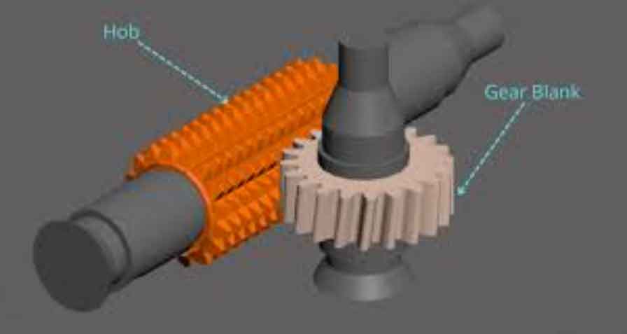
In a gear hobbing machine, the hob and the workpiece rotate in a coordinated manner. The hob acts like a moving rack, and the workpiece rotates as if it were meshing with that rack. The envelope of the hob tooth positions generates the involute tooth profile. When the process is applied to a face gear, the workpiece axis is reoriented so that the generated surface lies on the end face rather than on a cylindrical surface. This apparently simple change creates complex cutting force distributions, because the depth of cut, contact area, and number of active hob teeth vary continuously through each generating cycle. Therefore, face gear hobbing is not merely a variation of cylindrical gear hobbing; it demands a fixture that can resist time-varying loads in radial, axial, and tangential directions.
2. Kinematic Principle of Face Gear Gear Hobbing
I established a spatial coordinate system to describe the relative motion between the hob and the face gear during gear hobbing. Let the movable coordinate systems Sm(Xm, Ym, Zm) and Sn(Xn, Yn, Zn) represent the hob and the face gear, respectively. The hob rotates about the Zm axis at angular velocity ω2, while the workpiece rotates about the Z2 axis at angular velocity ω1. The center distance between the two axes is denoted by D. Auxiliary coordinate systems Ss and Sw are used to transform the motion. During a time interval t, the hob rotates through an angle θ2 and moves in the negative Xm direction. The coordinate system changes from Zm to Zw, and the axial distance to the face gear changes from D2 to D1. The face gear rotates through θ1, and its coordinate system changes from Zn to Zs. When the difference between d2 and d1 exceeds a specified height H, the tool moves upward in the Xm direction until the tool bottom separates completely from the face gear. It then moves along Zm by the next infeed depth and begins the cycle again.
The generating motion of gear hobbing can be understood by treating the face gear teeth as a rack with variable pressure angle and variable pitch. When the hob and the gear blank are forced to mesh according to the gear-rack transmission ratio, the consecutive positions of the hob teeth form an envelope that becomes the involute profile. As the hob feeds along the tooth width direction, the involute profile gradually extends across the face width. For a left-hand hob with helix angle θ, the installation angle λ is set to match the hob helix. When the hob is centered, one full rotation causes the face gear to index by one tooth pitch. At the same time, the hob feeds in the axial direction until it completely leaves the blank. Therefore, the gear hobbing process combines several motions:
- Cutting motion: the rotary primary motion of the hob.
- Vertical feed motion: the downward cutting feed and the upward return motion.
- Radial infeed motion: motion toward the gear center to establish the tooth depth.
- Circular generating motion: the coordinated rotation between hob and workpiece.
- Differential motion: an additional workpiece rotation used for helical gears when required.
For face gear hobbing, the axial and radial relationships become more complex because the generated tooth surface lies on the face of the blank. The hob must remove material from the end face while the workpiece rotates continuously. The cutting action is therefore intermittent at the tooth level but continuous in the generating sense. This is why the fixture must not only locate the workpiece accurately but also absorb periodic impulses from the gear hobbing cutter.
3. Limits Imposed by Root Undercut and Tip Sharpening
Face gear tooth width cannot be selected arbitrarily. If the tooth length is too large, the outer end may become pointed. If the inner radius is too small, root undercut may occur. The limiting radii can be expressed in terms of the module m and the number of teeth z. From the generating geometry, the minimum inner radius and maximum outer radius are approximately:
$$ r_{\min} \approx 0.4698 m z + 0.6977 $$
$$ r_{\max} \approx 0.5374 m z + 2.6977 $$
These equations provided me with a practical boundary for the gear blank design. They also helped me avoid tooth geometries that would be impossible to generate by gear hobbing without severe undercut or tip sharpening. In the experimental work, I used these limits to define the allowable face width and radius range for a 54-tooth face gear with module 2.5 mm.
| Parameter | Meaning | Effect on Face Gear Hobbing |
|---|---|---|
| Module m | Tooth size index | Larger module increases cutting force and fixture load |
| Number of teeth z | Tooth count of the face gear | Influences indexing ratio and tooth curvature |
| Inner radius rmin | Limit against root undercut | Prevents excessive material removal near the root |
| Outer radius rmax | Limit against tip sharpening | Prevents pointed teeth at the outer end |
| Face width b | Width of the generated tooth surface | Controls contact area and machining time |
4. Cutting Force in Face Gear Gear Hobbing
The cutting force in gear hobbing is one of the most important parameters for fixture design. It determines the clamping force, the required stiffness, the bearing selection, and the risk of vibration. I therefore analyzed the cutting force before modifying the tooling. The cutting model was simplified under several assumptions: inertial force due to chip momentum was neglected; friction on the flank face was neglected; the cutting action was treated as orthogonal; and the workpiece material was assumed to be homogeneous, isotropic, and incompressible elastic-plastic material. These assumptions are reasonable for the range of cutting speeds used on the available gear hobbing machine.
At a given instant, the force system on the workpiece can be represented by a shear-plane model. The resultant cutting force can be decomposed into a horizontal component and a vertical component. If τ is the shear stress, K is the cutting width, H is the uncut chip thickness, φ is the shear angle, β is the friction angle, and γ is the rake angle, then the principal components can be expressed as:
$$ F_r = \frac{K H \tau \sin\phi}{\sin\phi \cos(\phi+\beta-\gamma)} $$
$$ F_n = \frac{K H \tau \sin(\beta-\gamma)}{\sin\phi \cos(\phi+\beta-\gamma)} $$
Because the hob tooth has a trapezoidal shape, the cutting force comes from both the top edge and the side edges. In one complete generating cycle, a top edge and two side edges participate in cutting, but not always simultaneously. The left and right side edges remove different cross-sectional areas, and even the top edge removes an uneven chip thickness. Therefore, the force on the left side and the force on the right side are unequal. This imbalance produces a lateral resultant force on the hob and a time-varying load on the fixture. It is one of the main reasons why a fixture that works for resin face gears may fail during metal face gear hobbing.
For practical estimation, I used an empirical equation for the maximum gear hobbing force. In a form suitable for the present study, the maximum force can be written as:
$$ F_{\max}=0.0098 \left(2000 M_n^{0.95} S_a^{0.8} t^{0.15} e^{0.012\beta} C_g \right) \frac{e^{0.65\chi Z_n^{-0.35}} C_w}{V^{0.28} i^{0.7} A^{0.6}} $$
where Mn is the normal module, Sa is the axial feed, t is the cutting depth, β is the helix angle, Cg is the hob-head coefficient, χ is the tooth profile correction coefficient, Zn is the workpiece tooth number, Cw is the workpiece material coefficient, V is the cutting speed, i is the number of hob grooves, and A is the hob coefficient. The maximum resultant force can be decomposed into radial, axial, and tangential components:
$$ F = \sqrt{F_r^2 + F_a^2 + F_t^2} $$
For the purpose of fixture analysis, I used the following approximate relationships:
$$ F_r = (0.2\sim 0.6) F_t $$
$$ F_a = (0.2\sim 0.7) F_r $$
These relationships allowed me to define several load cases rather than relying on a single force direction. The radial component is especially important for face gear hobbing because the workpiece is supported on a cantilever-like bearing seat. The axial component can cause the blank to slide if the clamping system is not sufficiently preloaded. The tangential component tends to rotate the workholding plate about the machine table.
| Force component | Direction | Primary effect on fixture |
|---|---|---|
| Radial force Fr | Toward or away from gear center | Bending of the bearing seat and support plate |
| Axial force Fa | Along the workpiece axis | Axial slip, loosening of clamps, and bearing thrust |
| Tangential force Ft | Tangential to workpiece rotation | Rotation of the worktable and shear on location ribs |
| Resultant force F | Combined spatial direction | Overall deflection and vibration risk |
5. MATLAB Analysis of Gear Hobbing Parameters
I used MATLAB to examine how the empirical cutting force changes with the main gear hobbing parameters. The analysis was not intended to replace direct measurement, but to identify the dominant factors and to guide the fixture redesign. For a steel workpiece, the following trends emerged:
- The cutting force increases strongly with module. Increasing module from 10 to 25 in the parametric study produced a multiple-fold increase in force.
- For a fixed module, the force increases almost linearly with axial feed.
- At a hob head number of one, cutting speed has a relatively weak influence. As the number of hob heads increases, the force becomes more sensitive to cutting speed, especially below 100 m/min.
- Depth of cut has an obvious and direct effect because it changes the removed area and chip load.
- When the workpiece tooth number is below 100, the force changes noticeably with tooth number. Above 100, the change becomes much smaller.
Other factors also influence the gear hobbing force. Workpiece material and heat treatment directly determine machinability. Cutting fluid improves cooling and lubrication, reduces friction, and lowers the effective cutting resistance. The contact point between hob and workpiece changes continuously, so the cutting speed at the contact point is not constant. Tool geometry also matters: a sharper hob with suitable rake and relief angles requires less force. These observations helped me choose conservative cutting parameters for the first metal face gear hobbing trial.
| Parameter | Trend observed | Practical implication for gear hobbing |
|---|---|---|
| Module | Force rises rapidly with module | Use smaller depth increments for large modules |
| Axial feed | Force rises with feed | Reduce feed during roughing if fixture stiffness is limited |
| Cutting speed | Weak effect at one hob head, stronger at multiple heads | Select speed within machine range and avoid unstable zones |
| Depth of cut | Dominant influence on force magnitude | Use multiple passes for steel face gears |
| Workpiece tooth number | Strong below 100 teeth, weak above 100 | Pay attention to small and medium tooth counts |
6. Original Face Gear Hobbing Fixture and Its Limitations
The original fixture had been designed for principle experiments. It could support resin face gear hobbing, but when the cutting depth was increased, vibration appeared. In some trials, the fixture could not complete the cut at all. This showed that the original design was stiffness-limited. The original fixture consisted of a workplate, location ribs, a bearing seat, a clamping plate, a bevel gear pair, and a workpiece shaft. The clamping plate was welded to the location ribs and then tightened by four screws. This created a cantilever clamping condition. The clamping force was limited, and the reaction force acted on the location ribs, which reduced the overall stability of the fixture.
For a metal face gear, especially one made of 45 steel, the cutting force is much higher than for resin. The original fixture therefore had to be analyzed quantitatively. I used SolidWorks for three-dimensional modeling and ANSYS Workbench for finite element analysis. The workbench platform allowed me to connect the CAD model directly and to update geometry parameters without rebuilding the entire model. I simplified the assembly by removing screws, keyways, small holes, and other features that do not significantly affect stiffness but greatly increase mesh complexity. Bearings were replaced by equivalent material sleeves, and contact conditions were assigned according to the actual load path.
| Part | Material | Density (kg/m3) | Young’s modulus (Pa) | Poisson’s ratio |
|---|---|---|---|---|
| Main structural parts | 45 steel | 7890 | 2.09 × 10¹¹ | 0.269 |
| Support plates | Q235 | 7850 | 2.10 × 10¹¹ | 0.33 |
| Equivalent bearing sleeves | GCr15 | 7900 | 2.79 × 10¹¹ | 0.30 |
I defined contact pairs between the shaft and bearing seat, between the bearing seat and workplate, between the location ribs and workplate, and between the clamping plate and workplate. Bonded contact was used where no relative motion should occur. No-separation contact was used for surfaces that could slide slightly but should not separate. Frictionless contact was used where normal pressure could vary. Frictional contact was used for the clamping screw interface with a friction coefficient of 0.15. The mesh was controlled with an aggressive shape check, and midside nodes were retained for higher-order elements.
| Contact type | Contact surface | Target surface |
|---|---|---|
| Bonded | Shaft side surface | Bearing seat inner bore |
| Bonded | Bearing seat bottom face | Workplate top surface |
| Bonded | Workplate threaded hole surfaces | Bearing seat through-hole surfaces |
| Bonded | Location rib side faces | Workplate corresponding surfaces |
| Bonded | Location rib lower face | Workplate corresponding surface |
| No separation | Worktable cylindrical side | Workplate corresponding surface |
| Frictionless | Worktable upper surface | Workplate corresponding surface |
| Frictional | Clamping screw lower face | Workplate upper surface |
I applied boundary conditions by fixing the lower surface of the machine table and the rear end face of the location ribs. The cutting force was applied to a simplified tooth-space feature on the top of the gear blank. The tooth-space geometry was approximated as a trapezoid. For a 54-tooth face gear, the tooth-space depth was about 5.625 mm. The top width was set to approximately 1.5 mm to represent the hob tooth tip, and the bottom width was set between 4.5 mm and 5 mm. This simplification made it possible to apply the radial, axial, and tangential force components in a controlled manner.
| Load case | Fr to Ft ratio | Fa to Fr ratio | Radial force Fr (kN) | Axial force Fa (kN) | Tangential force Ft (kN) |
|---|---|---|---|---|---|
| 1 | 0.2 | 0.2 | 62.79 | 12.56 | 12.56 |
| 2 | 0.6 | 0.2 | 55.15 | 11.03 | 33.09 |
| 3 | 0.2 | 0.7 | 52.75 | 36.93 | 10.55 |
| 4 | 0.6 | 0.7 | 47.97 | 33.58 | 28.78 |
The static analysis showed that the maximum displacement of the original fixture exceeded 1 mm in all four load cases. Such a large deflection makes accurate gear hobbing impossible. The equivalent stress was concentrated on the workplate near the bearing seat. The workplate tended to lift in the vertical direction because the clamping was not sufficiently rigid. The location ribs also experienced reaction forces because the clamping plate was welded to them. I concluded that the original fixture needed two major improvements: a better upper clamping mechanism and a stiffer support arrangement for the cantilever bearing seat.
| Load case | Maximum displacement before improvement (mm) | Maximum displacement after improvement (mm) |
|---|---|---|
| 1 | 1.045 | 0.048 |
| 2 | 1.576 | 0.057 |
| 3 | 1.977 | 0.060 |
| 4 | 1.559 | 0.042 |
7. Improved Clamping and Support Design
The original clamping plate was a cantilever. For steel gear hobbing, the clamping force had to be increased and the load path had to be changed. I removed the original upper clamping plate and replaced it with a combination table. Four long studs were connected to the central threaded holes in the workplate. A top plate was then bolted to the studs. By adjusting four nuts at the lower ends of the studs, the upper and lower plates could be made parallel. The lower plate transferred its load to the upper plate, and the upper plate was pressed directly by the machine spindle. This arrangement greatly increased the vertical restraint of the workplate.
I considered two possible pressing schemes. In the first scheme, the existing M30 nut on the gear hobbing machine spindle was used to provide a downward clamping force. Because the nut rotates with the spindle, I placed a thrust ball bearing below the nut. A pressure cap was inserted between the nut and the bearing. The spindle passed through the central hole of the cap. The lower end of the cap mated with the bearing to prevent lateral sliding. A support tube made of seamless steel pipe was fitted below the thrust bearing. The upper end of the tube was welded with a thick washer and then turned to form a proper seat. The lower end of the pressure cap retained about 15 mm of thread for pressing the bevel gear. In the second scheme, the machine overarm was used to press the workplate through a support tube. The overarm was restrained by a pressing block attached to the column. After comparing the two schemes, I selected the first because it was more direct and reliable, although it required more careful machining of the cap and tube.
I also changed the bearing seat height. The original bearing seat was 272 mm high. This created a long cantilever and a large bending moment on the workplate. The machine allowed the hob axis to be positioned between 235 mm and 535 mm above the worktable. I reduced the bearing seat height to 150 mm. This shortened the cantilever, reduced the moment arm, and lowered the stress concentration near the workplate. To maintain alignment, I cut the original bearing seat and reconnected it by keyed joints and welding. The seat was then finish-machined. I also replaced the original straight bevel gears with spiral bevel gears to improve transmission smoothness and load capacity. The spiral bevel pair reduced impact and made the gear hobbing drive more stable.
| Design change | Original condition | Improved condition | Purpose |
|---|---|---|---|
| Upper clamping | Cantilever plate welded to ribs | Combination table with studs and top plate | Increase vertical restraint and reduce rib loading |
| Bearing seat height | 272 mm | 150 mm | Reduce bending moment on workplate |
| Bevel gear type | Straight bevel | Spiral bevel | Improve transmission smoothness and load capacity |
| Bearing seat top support | Unsupported cantilever | Screw-pressed support block | Reduce stress concentration |
| Workplate pressing | Four screws on welded plate | Spindle M30 nut and thrust bearing | Apply higher and more stable clamping force |
8. Static and Modal Analysis of the Improved Fixture
After redesign, I rebuilt the assembly and repeated the finite element analysis. The mesh was regenerated, contact conditions were reassigned, and the same four load cases were applied. The maximum displacement of the improved fixture was below 0.06 mm in all cases. This represented a reduction of more than one order of magnitude compared with the original fixture. The stress concentration near the workplate was also greatly reduced. The new support block at the top of the bearing seat helped stabilize the cantilever and distributed the load more evenly.
I then performed a modal analysis to identify the natural frequencies of the fixture. The first four natural frequencies were approximately 374.84 Hz, 409.8 Hz, 487.36 Hz, and 798.08 Hz. The first and fourth mode shapes showed maximum deformation on the workpiece, which means that these modes could affect tooth profile accuracy during gear hobbing. However, the excitation frequency from the hob teeth is much lower. For a hob with ten teeth on the end face, the blade frequency is:
$$ f_b = \frac{n_s z_b}{60} $$
where ns is the spindle speed in r/min and zb is the number of hob teeth. The blade frequencies for the available spindle speeds are shown below.
| Spindle speed (r/min) | 40 | 50 | 63 | 80 | 100 | 125 | 160 | 200 | 250 |
|---|---|---|---|---|---|---|---|---|---|
| Blade frequency (Hz) | 6.67 | 8.33 | 10.50 | 13.33 | 16.67 | 20.33 | 26.67 | 33.33 | 41.67 |
The natural frequencies of the improved fixture are far above the blade frequency range. Therefore, resonance is unlikely under normal gear hobbing conditions. This gave me confidence that the fixture could support metal face gear hobbing without excessive vibration.
9. Manufacturing and Installation of the Improved Fixture
I manufactured the improved fixture according to the design. The bearing seat was shortened by cutting and welding. Keyed joints were used to maintain alignment during welding. The upper clamping plate and support tube were machined to ensure coaxiality between the thrust bearing, pressure cap, and seamless tube. The location ribs were cleaned and ground where necessary. I installed the spiral bevel gear pair, the deep groove ball bearing, the thrust ball bearing, and the workplate in the correct sequence. A spirit level was used to align the workplate with the machine table. The location ribs were then bolted in place, and the seamless tube was inserted over the spindle. The M30 nut was tightened after the tube contacted the bevel gear. The bearing seat assembly was preassembled on a bench. The workpiece blank was located by its rear face against a round nut. I checked that the round nut end face was perpendicular to the shaft axis. The bearing seat was then connected to the workplate through a location key, and shims were used to adjust the bevel gear mesh.
The hob installation also required careful attention. The hob arbor was inserted into the spindle taper and pulled tight. The hob was positioned so that its center aligned with the centerline of the face gear blank. If the hob is offset, the generated tooth form becomes asymmetrical. I used adjustment spacers on both sides of the hob. The hob installation angle was set equal to the hob helix angle. For a left-hand hob with helix angle about 2°29′, the cutter head was rotated accordingly. Because the process used climb milling, the downward feed had to extend beyond the face gear blank without touching the workpiece shaft or fixture. I adjusted the stroke stop block to ensure a complete cut and safe return.
10. Selection of Gear Hobbing Parameters
For the metal face gear trial, I selected a 45 steel blank with 54 teeth, module 2.5 mm, and face width 10 mm. The hob had a diameter of 63 mm, one head, and a left-hand helix. I calculated the index change gears from the gear hobbing machine transmission balance. For a hob with K heads and a workpiece with Z teeth, the generating ratio is:
$$ \frac{\omega_{\text{work}}}{\omega_{\text{hob}}} = \frac{K}{Z} $$
On the available machine, the index change gear formula can be written as:
$$ \frac{e}{f}\frac{a}{b}\frac{c}{d} = \frac{24K}{Z} $$
For K = 1 and Z = 54, I used e/f = 36/36 and selected a = 40 and d = 90. The index change gear conditions are summarized below.
| Range of Z/K | e | f | Change gear relation |
|---|---|---|---|
| 8 ≤ Z/K ≤ 20 | 48 | 24 | ac/(bd) = 12K/Z or 18K/Z |
| 21 ≤ Z/K ≤ 142 | 36 | 36 | ac/(bd) = 24K/Z or 36K/Z |
| Z/K ≥ 143 | 24 | 48 | ac/(bd) = 48K/Z or 72K/Z |
I selected the spindle speed from the machine table. For the 36/36 change gear ratio, the available speeds were 80, 125, and 100 r/min depending on the handle position. I also checked the minimum number of teeth that could be cut at each spindle speed. For a one-head hob, the minimum tooth counts are listed below.
| Spindle speed (r/min) | 40 | 50 | 63 | 80 | 100 | 125 | 160 | 200 | 250 |
|---|---|---|---|---|---|---|---|---|---|
| Minimum tooth number Z | 6 | 7 | 9 | 11 | 13 | 16 | 21 | 26 | 32 |
For roughing and finishing, I chose the feed rates according to the module and surface finish requirements. The roughing feed was 0.87 mm/r, and the finishing feed was 0.56 mm/r. The cutting speed was 125 mm/s. The depth of cut was divided into three passes: 2.5 mm, 2.5 mm, and 0.625 mm. This reduced the maximum force and protected the fixture. The final pass left a small finishing allowance and produced a smoother tooth surface.
| Operation | Axial feed Sa (mm/r) | Depth of cut t (mm) | Cutting speed V (mm/s) |
|---|---|---|---|
| Roughing | 0.87 | 2.5 | 125 |
| Finishing | 0.56 | 0.625 | 125 |
11. Metal Face Gear Gear Hobbing Trial
Before the trial, I coated the blank with a thin layer of matte black paint so that the cutting tracks would be visible. I installed the fixture and hob, adjusted the change gears, set the spindle speed, and selected the feed. I then started the gear hobbing cycle. During the first attempt, the face gear blank showed slight circumferential sliding and noticeable shaking. I stopped the machine and inspected the fixture. The problem was traced to insufficient tightening of the spiral bevel gear on the spindle. The two small round nuts and the seamless tube could not provide enough clamping force. I replaced the two small round nuts with a single M30 hexagon nut. After retightening, the bevel gear no longer slipped.
Another practical issue appeared when the blank had to be removed and repositioned. Because face gear teeth are generated by a continuous envelope, removing the workpiece interrupts the generating relationship. If the blank is repositioned, the existing teeth may not align perfectly with the new cut. For small experimental cuts, I could face the blank slightly and reset the depth so that the tooth region remained within the original blank dimensions. However, for production, the workpiece should not be removed until the gear hobbing cycle is complete. I also adjusted the cutting fluid so that it reached both the hob and the cutting zone. This improved chip flushing and reduced thermal load.
After completing the passes, I removed the face gear from the fixture and cleaned it. The tooth surfaces showed a continuous generated pattern. The fixture remained stable during the final passes, and no severe vibration was observed. The trial confirmed that the improved tooling could support metal face gear hobbing on the available machine.
12. Motion Simulation and Interference Checking
To evaluate the generated face gear geometry, I created a parametric model of a spur pinion and a face gear. I used a module of 2.5 mm, a pinion tooth number of 18, a face gear tooth number of 54, a pressure angle of 20°, and standard addendum and clearance coefficients. I assembled the two gears in a CAD environment with orthogonal axes. I created cylindrical reference axes for both gears, mated each gear concentrically to its axis, and set the axial distance so that the pinion addendum surface was 0.625 mm from the face gear root surface. I then added a mechanical gear mate with a ratio of 18:54.
For the motion simulation, I applied a rotary motor to the pinion. The motor speed was 100 r/min, and the simulation was run for 10 seconds. The animation was set to reciprocating mode so that the full mesh cycle could be observed. During the simulation, I noticed that when the face gear had 54 teeth, a pinion with 19 or more teeth produced excessive interference. The simulation could not complete the mesh motion smoothly. Therefore, for a 54-tooth face gear, the pinion tooth number should remain below 19 for this geometry.
I then performed an interference check for several face gear radius combinations. The allowable radius range from the limiting equations was about 64.12 mm to 93.25 mm. I divided this range into increments of 2.5 mm and built a series of models. The interference volume decreased as the face gear radius decreased. The smallest interference occurred at an inner radius of 65 mm and an outer radius of 75 mm. The interference values for the tested cases are summarized below.
| Inner radius (mm) | Outer radius (mm) | Interference volume (mm3) |
|---|---|---|
| 75 | 85 | 0.001 |
| 72.5 | 82.5 | 0.0025 |
| 70 | 80 | 0.00081 |
| 67.5 | 77.5 | 0.00035 |
| 65 | 75 | 0.00013 |
13. Contact Pattern Detection and Accuracy Analysis
After gear hobbing, I assembled the metal face gear with a standard spur pinion on a simple meshing test stand. I coated the pinion teeth with red lead powder and rotated the pinion through one full revolution. The contact marks transferred to the face gear teeth. I recorded the contact pattern for each tooth and measured the percentage of contact along the tooth height and tooth length. The contact percentage along the tooth height was calculated as:
$$ P_h = \frac{h”}{h’} \times 100\% $$
The contact percentage along the tooth length was calculated as:
$$ P_b = \frac{b” – c}{b’} \times 100\% $$
where h″ is the average height of the contact mark, h′ is the working tooth height, b″ is the total length of the contact mark, c is the length of any broken segment, and b′ is the working tooth length. The measured contact percentages along the tooth height are listed below.
| Tooth group | Contact percentage along tooth height |
|---|---|
| Group 1 | 41%, 45%, 44%, 39%, 38%, 40% |
| Group 2 | 46%, 44%, 43%, 43%, 42%, 45% |
| Group 3 | 48%, 45%, 42%, 49%, 51%, 50% |
The average contact percentage along the tooth height was about 44.17%, which is below 45%. This indicates that the face gear accuracy was not better than grade 7. The gear hobbing process produced a tooth form that differed somewhat from the theoretical meshing form. I observed two main phenomena. First, some tooth surfaces showed multiple ridges or waviness. Second, some tooth profiles were asymmetrical. I analyzed the causes as follows.
Ridges on the tooth surface can come from poor indexing of the hob teeth along the face gear circumference. If the hob teeth are not equally spaced, some regions are over-cut while others are under-cut. The effect is stronger when the tooth curvature is large, which is typical for face gears with small tooth numbers. Hob runout and axial play also cause over-cut and under-cut. Asymmetry can come from non-axiality of the hob front face, which makes the left and right cutting edges deviate differently from the correct profile. Poor hob centering is another cause. If the hob is not centered on the blank centerline, the generated face gear is not truly orthogonal. The effect becomes more severe when the number of hob teeth enveloping the surface is small and the tooth curvature is large.
Machine errors also contribute. Index worm gear errors, change gear errors, worktable spindle stiffness, and machine vibration all influence the final tooth form in gear hobbing. To reduce these errors, I recommend using a high-precision hob, improving hob centering, increasing fixture stiffness, and avoiding unnecessary removal and reinstallation of the workpiece. For face gears with large module and small tooth number, a dedicated centering gauge can improve alignment. If necessary, the tooth surface can be corrected by a finishing operation or a controlled modification of the hob profile.
14. Discussion of Gear Hobbing Tooling Improvement
The improved tooling demonstrated that a general-purpose gear hobbing machine can be used for metal face gear experiments when the fixture is designed around the actual cutting force and vibration behavior. The most important lesson I learned is that the clamping system must not rely on a cantilever. The original clamping plate transmitted its reaction into the location ribs, which were not intended to carry the vertical component of the gear hobbing force. By changing to a combination table and using the spindle nut with a thrust bearing, I created a direct and stiff load path from the top plate to the machine spindle. This reduced the vertical displacement dramatically.
The second lesson is that the bearing seat height has a strong influence on the overall flexibility. A cantilever bearing seat multiplies the radial force into a bending moment on the workplate. Reducing the height from 272 mm to 150 mm reduced this moment and lowered the stress concentration. The additional top support screw further stabilized the bearing seat. The spiral bevel gear pair also improved the transmission smoothness, which is important because the gear hobbing drive experiences periodic load changes. These changes were not merely local reinforcements; they altered the structural load path of the entire fixture.
The third lesson is that modal analysis should be performed before the first metal cutting trial. The first natural frequency of the improved fixture was well above the blade frequency range. This does not guarantee zero vibration, but it reduces the risk of resonance. If a natural frequency had fallen within the operating range, I would have had to change the structure again. Therefore, modal analysis is a valuable tool for gear hobbing tooling design, especially when the workpiece material changes from polymer to metal.
15. Practical Recommendations for Metal Face Gear Gear Hobbing
Based on the analysis and the trial, I offer the following recommendations for future work on metal face gear gear hobbing:
- Use a cutting force model that includes radial, axial, and tangential components. A single resultant force is not sufficient for fixture design.
- Design the clamping system so that the main cutting force is transferred directly to a rigid machine element, not through a cantilever or welded bracket.
- Keep the bearing seat as short as possible while maintaining the required hob-to-workpiece center distance.
- Use spiral bevel gears or other smooth transmission elements in the gear hobbing drive train to reduce impact.
- Select the index change gears carefully and verify the minimum tooth number allowed at the chosen spindle speed.
- Divide the total depth of cut into multiple passes when cutting steel face gears. The depth of cut has a dominant effect on the gear hobbing force.
- Use sufficient cutting fluid and direct it to both the hob and the cutting zone.
- Do not remove the workpiece from the fixture during a gear hobbing cycle unless absolutely necessary.
- Check hob centering and hob runout before cutting. Poor centering causes asymmetrical tooth profiles.
- Perform contact pattern detection after gear hobbing and use the result to adjust the process.
16. Conclusions
I studied face gear gear hobbing with the goal of improving the tooling so that metal face gears could be machined on a general-purpose gear hobbing machine. I established the kinematic relationship between the hob and the face gear, derived the limiting radii for root undercut and tip sharpening, and analyzed the cutting force using both a theoretical model and an empirical formula. I used MATLAB to investigate how module, axial feed, cutting speed, depth of cut, and tooth number affect the gear hobbing force. The results showed that depth of cut and module are the most influential parameters, while the influence of cutting speed depends on the number of hob heads.
I then modeled the original fixture and performed static finite element analysis. The original fixture deflected by more than 1 mm under representative gear hobbing loads, which explained why it could not cut metal face gears. The stress concentration was found near the workplate and bearing seat. I redesigned the clamping system, shortened the bearing seat, added a top support, and replaced the straight bevel gears with spiral bevel gears. The improved fixture reduced the maximum displacement to less than 0.06 mm. Modal analysis showed that the first four natural frequencies were well above the blade frequency range, so resonance was unlikely during gear hobbing.
I manufactured and installed the improved fixture, selected the index change gears, spindle speed, feed rate, and depth of cut, and completed a metal face gear gear hobbing trial. The trial confirmed that the improved tooling could withstand the cutting load and maintain stability. I also built a parametric gear model, performed a motion simulation, and checked meshing interference. The smallest interference occurred at an inner radius of 65 mm and an outer radius of 75 mm for the 54-tooth face gear. Finally, I conducted a contact pattern detection test. The average contact percentage along the tooth height was about 44.17%, indicating that the accuracy was not better than grade 7. I identified hob indexing error, hob runout, poor centering, machine transmission error, and fixture stiffness as the main causes of tooth profile error.
Overall, the improved face gear hobbing tooling provides a practical foundation for further research. It shows that careful force analysis, finite element modeling, modal assessment, and incremental process selection can extend the capability of a conventional gear hobbing machine. Future work can focus on higher-precision hobs, in-process measurement, adaptive clamping force control, and optimized tooth surface correction. These developments would help move face gear gear hobbing from experimental trials toward more reliable and efficient production.