
I study the cutting force and cutting deformation that occur during the hobbing of cycloidal gears used in RV reducers. In my work, the cycloidal gear is treated as a core functional component of the reducer, and its porous structure is one of the main reasons why the gear can deform during gear machining. Because the gear has several circular holes and trapezoidal holes, its stiffness is not uniform. This non-uniform stiffness changes the local cutting condition, influences the instantaneous cutting force, and ultimately affects the tooth profile accuracy. My objective is to connect the geometry of the cycloidal gear, the geometry of the hob, the kinematics of gear machining, the finite element prediction of cutting force, and the finite element prediction of cutting deformation into one consistent analysis framework. I derive the tooth profile equations, build the hob edge equations, construct the spatial surface cluster of the hob edges, simplify the gear machining process into a single-tooth and single-groove model, validate the cutting force model, and then use the validated model to study deformation in weak-rigidity and medium-rigidity zones.
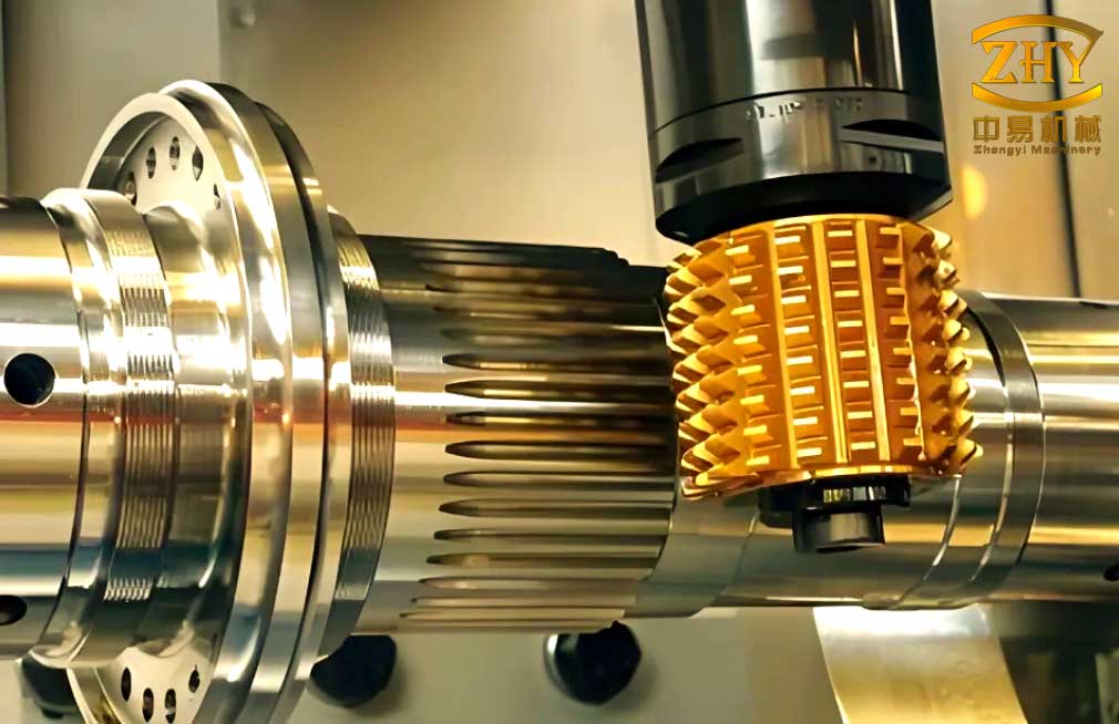
Geometric Modeling of the Cycloidal Gear and the Hob
I begin with the cycloidal gear tooth profile. The profile is generated by the enveloping method and the gear meshing principle. The gear pair is formed by an arc and an equidistant curve of a shortened epicycloid. I fix the cycloidal gear to a coordinate frame and the pin gear to another coordinate frame. The pin gear rotates relative to the cycloidal gear, and the pin centers generate the shortened epicycloid. The equidistant curve is then obtained by offsetting the epicycloid by the pin radius. This is the geometric basis of the cycloidal tooth profile used in gear machining.
Let the pin gear radius be R2, the eccentricity be e, the cycloidal gear base radius be r1, the pin gear base radius be r2, and the pin radius be rz. The rotation angles are φ1 and φ2. The parametric form of the cycloidal gear profile can be written as:
$$ \begin{aligned}
X_1 &= R_2\cos\phi_2 – e\cos\phi_1 – r_z \frac{R_2\cos\phi_2 – e\cos\phi_1}{\sqrt{R_2^2+e^2-2R_2e\cos(\phi_1-\phi_2)}},\\
Y_1 &= R_2\sin\phi_2 – e\sin\phi_1 – r_z \frac{R_2\sin\phi_2 – e\sin\phi_1}{\sqrt{R_2^2+e^2-2R_2e\cos(\phi_1-\phi_2)}}.
\end{aligned} $$
The angular relation between the two rotations is:
$$ \frac{\phi_2}{\phi_1} = \frac{r_1}{r_2} = \frac{r_1}{r_1+e}. $$
I use this relation to generate the full cycloidal tooth profile. The basic parameters used in my model are listed in the table below. These parameters define the geometric boundary of the cycloidal gear before gear machining and also define the conjugate relation between the gear and the hob.
| Parameter | Symbol | Value |
|---|---|---|
| Pin gear radius | R2 | 82 mm |
| Eccentricity | e | 1.5 mm |
| Cycloidal gear base radius | r1 | 38.5 mm |
| Pin gear base radius | r2 | 40 mm |
| Pin radius | rz | 7 mm |
| Rotation angle range | φ1 | 10° to 360° |
The hob is the tool that performs gear machining. I treat the hob as a conjugate worm-type tool. The hob edge profile is obtained from the conjugate condition between the cycloidal gear and the hob. I define a coordinate frame OCXCYC that is fixed to the hob. The transformed hob edge profile in this frame is:
$$ \begin{aligned}
X_C’ &= X_1\cos\eta – Y_1\sin\eta + r_1,\\
Y_C’ &= X_1\sin\eta + Y_1\cos\eta – r_1,
\end{aligned} $$
where the angle η satisfies the conjugate condition:
$$ \eta = \frac{\pi}{2} – \arccos\left(\frac{X_1\cos\gamma + Y_1\sin\gamma}{r_1}\right) + \gamma. $$
The hob tooth height, normal pitch, module, pitch diameter, helix angle, and axial pitch are determined from the gear geometry and the hob design. I use the following relations:
$$ h_0 = 2(r_a – r_f) = 2e, $$
$$ p_n = \frac{2\pi r_a}{Z_1}, $$
$$ m = \frac{p_n}{\pi}, $$
$$ d_0 = d – 2h_0 = d – 4e, $$
$$ \sin\gamma_z = \frac{m Z_0}{d_0}, $$
$$ p_x = \frac{p_n}{\cos\gamma_z}. $$
In these equations, h0 is the hob tooth height, pn is the normal pitch, m is the module, d0 is the pitch diameter, γz is the helix angle, px is the axial pitch, Z1 is the number of cycloidal gear teeth, Z0 is the number of hob starts, and d is the hob outer diameter. The hob parameters used in my gear machining model are summarized below.
| Hob parameter | Symbol | Relation or value |
|---|---|---|
| Hob tooth height | h0 | 2e |
| Normal pitch | pn | 2πra/Z1 |
| Module | m | pn/π |
| Pitch diameter | d0 | d − 4e |
| Helix angle | γz | arcsin(mZ0/d0) |
| Axial pitch | px | pn/cosγz |
| Number of starts | Z0 | 1 |
| Number of flutes | ZK | 10 to 14 |
Kinematic Model of Cycloidal Gear Hobbing
Gear machining by hobbing is a continuous generating process. The hob and the workpiece maintain a strict generating motion, while the hob also feeds along the workpiece axis. In my kinematic model, I define several coordinate frames: the workpiece frame, the machine table frame, the column frame, the axial slide frame, the tangential slide frame, and the hob frame. The relative motion between the hob and the workpiece is described by homogeneous coordinate transformation matrices. This is necessary because gear machining with a hob involves coupled rotation, axial feed, and sometimes tangential feed and radial feed.
The transformation matrix from the hob frame to the tangential slide frame is:
$$ M_{65} = \begin{bmatrix}
1&0&0&0\\
0&\cos\phi_1&-\sin\phi_1&0\\
0&\sin\phi_1&\cos\phi_1&0\\
0&0&0&1
\end{bmatrix}. $$
The transformation matrix from the tangential slide frame to the axial slide frame is:
$$ M_{54} = \begin{bmatrix}
\cos\gamma_{an}&0&\sin\gamma_{an}&x_z\cos\gamma_{an}\\
0&1&0&0\\
-\sin\gamma_{an}&0&\cos\gamma_{an}&x_z\sin\gamma_{an}\\
0&0&0&1
\end{bmatrix}. $$
The transformation matrix from the axial slide frame to the column frame is:
$$ M_{43} = \begin{bmatrix}
1&0&0&0\\
0&1&0&0\\
0&0&1&z_a\\
0&0&0&1
\end{bmatrix}. $$
The transformation matrix from the column frame to the machine table frame is:
$$ M_{32} = \begin{bmatrix}
1&0&0&0\\
0&1&0&-h_0\\
0&0&1&0\\
0&0&0&1
\end{bmatrix}. $$
The transformation matrix from the machine table frame to the workpiece frame is:
$$ M_{21} = \begin{bmatrix}
\cos\phi_2&\sin\phi_2&0&0\\
-\sin\phi_2&\cos\phi_2&0&0\\
0&0&1&0\\
0&0&0&1
\end{bmatrix}. $$
The full transformation from the hob frame to the workpiece frame is:
$$ M_{61} = M_{65}M_{54}M_{43}M_{32}M_{21}. $$
Any point on the hob can be transformed into the workpiece frame by:
$$ r_{pw}^{(1)} = M_{16} r_{phr}^{(6)}. $$
The velocity of the same point in the machine table frame is obtained from the rotational and translational velocity components:
$$ v_{ph}^{(2)} = \omega_1^{(2)} \times r_{ph}^{(2)} + \omega_2^{(2)} \times R_a^{(2)} + v_t^{(2)} + v_a^{(2)} + v_r^{(2)}. $$
The relative velocity between the hob and the workpiece at the contact point is:
$$ v_{phw}^{(2)} = v_{ph}^{(2)} – v_{pw}^{(2)}. $$
For the hob edge, I number the teeth and describe their spatial positions. The spatial surface cluster generated by the hob edges is:
$$ G_i(\varphi) = R_x(\varphi) R_z(\psi) T_z(\zeta) r_{hi}. $$
The axial feed and the rotational phase are expressed as:
$$ \zeta(\varphi) = \frac{n f}{2\pi z}\varphi, \quad \psi(\varphi) = \pm \frac{z_0}{z}\varphi. $$
Here, n is the number of workpiece revolutions, f is the axial feed per workpiece revolution, z is the number of gear teeth, and z0 is the number of hob starts. This surface cluster is the geometric basis for extracting the undeformed chip in gear machining. The chip is formed between two adjacent hob edge surfaces and the workpiece boundaries.
The undeformed chip thickness can be calculated from the distance between adjacent surfaces:
$$ h_i = \left| \frac{\partial G_i}{\partial i} \times \frac{\partial G_i}{\partial \varphi} \right| – \left| \frac{\partial G_{i+1}}{\partial (i+1)} \times \frac{\partial G_{i+1}}{\partial \varphi} \right|. $$
The chip volume is the integral of the thickness over the surface parameter domain:
$$ V_i = \iint h_i \left| \frac{\partial G_i}{\partial i} \times \frac{\partial G_i}{\partial \varphi} \right| di\,d\varphi. $$
The projected area is:
$$ A_i = \iint \left| \frac{\partial G_i}{\partial i} \times \frac{\partial G_i}{\partial \varphi} \right| di\,d\varphi. $$
The average chip thickness is:
$$ h_{avg} = \frac{V_i}{A_i}. $$
I divide the axial feed process into three stages: the entry stage, the full-cutting stage, and the exit stage. The full-cutting stage occupies most of the gear machining time and is not affected by the upper and lower end faces of the workpiece. Therefore, I focus my cutting force and deformation analysis on the full-cutting stage.
| Stage | Description | Role in gear machining |
|---|---|---|
| Entry stage | Hob begins to cut the blank until a complete tooth profile begins to form. | Short duration; chip volume increases rapidly. |
| Full-cutting stage | Hob cuts through the middle region of the gear width. | Dominant stage; chip geometry is stable and representative. |
| Exit stage | Hob approaches and leaves the lower end face. | Short duration; chip volume decreases. |
For the full-cutting stage, I analyze one cutting cycle of a single tooth groove. The undeformed chips generated by edges 1 through 8 are extracted. The chip length does not change strongly within one cutting cycle, but the chip thickness changes significantly. The chip is thicker at the circumferential entry and exit positions, and thinner in the middle positions. The chip width is also larger at edges 1, 2, and 8, because the cutting allowance near the tooth convex region is larger than that near the tooth concave region.
| Edge number | Relative chip length | Relative chip width | Maximum chip thickness |
|---|---|---|---|
| 1 | Long | Wide | 0.30 mm |
| 2 | Long | Wide | 0.28 mm |
| 3 | Medium | Narrow | 0.20 mm |
| 4 | Medium | Narrow | 0.18 mm |
| 5 | Medium | Narrow | 0.17 mm |
| 6 | Medium | Narrow | 0.15 mm |
| 7 | Long | Medium | 0.25 mm |
| 8 | Long | Wide | 0.35 mm |
The longest undeformed chip in my model is about 13 mm, and the shortest is about 11.5 mm. The maximum chip thickness ranges from about 0.15 mm to about 0.35 mm. These values are important because the cutting force in gear machining is strongly influenced by the chip cross-section. In particular, edge 8 produces the thickest and most stable chip, so I use the edge 8 cutting position as the representative position for cutting force collection and deformation loading.
Finite Element Model for Cutting Force in Gear Machining
I simplify the full cycloidal gear hobbing process into a single-tooth and single-groove model. This simplification is justified because the tooth grooves are generated sequentially and periodically, and the chip thickness is much smaller than the local workpiece thickness. Therefore, the influence of cutting force on deformation is stronger than the influence of deformation on cutting force. The simplified model allows me to control the cutting position and the cutting parameters while keeping the calculation efficient.
The finite element control equation for the large-deformation, large-strain-rate, thermo-mechanical problem is:
$$ \int_V B^T S\,dV = \int_V N^T f_i\,dV + \int_A N^T F_i\,dA. $$
Here, B is the strain-displacement matrix, S is the stress tensor, N is the shape function, fi is the body force, and Fi is the surface force. The workpiece material is 25CrMo4 steel, and the hob material is M35. The workpiece is modeled as an elastic-plastic material with temperature-dependent properties.
I use the Johnson-Cook constitutive model to describe the flow stress of the workpiece:
$$ \sigma = (A+B\epsilon^n)\left(1+C\ln\frac{\dot\epsilon}{\dot\epsilon_0}\right)(1-T^{*m}). $$
The homologous temperature is:
$$ T^* = \frac{T-T_{room}}{T_{melt}-T_{room}}. $$
The material constants used in my simulation are listed below.
| Parameter | Symbol | Value |
|---|---|---|
| Quasi-static yield strength | A | 1200 MPa |
| Strain hardening parameter | B | 891 MPa |
| Strain rate sensitivity | C | 0.02 |
| Hardening exponent | n | 0.2 |
| Thermal softening exponent | m | 0.64 |
| Reference strain rate | ε0 | 1 s−1 |
| Room temperature | Troom | 293 K |
| Melting temperature | Tmelt | 1800 K |
| Poisson ratio of workpiece | ν | 0.3 |
| Density of workpiece | ρ | 7.85 × 10⁻⁶ kg/mm3 |
The fracture separation criterion is based on the accumulated plastic strain and the tensile stress state:
$$ \int_0^{\epsilon_f} \frac{d\epsilon}{\sigma^*} = C_4, $$
$$ \sigma^* = \begin{cases}
1, & \sigma_1 \ge 0,\\
0, & \sigma_1 < 0.
\end{cases} $$
I use a sticking-sliding friction model at the tool-chip interface:
$$ \tau_f = \begin{cases}
k_{chip}, & \mu\sigma_n \ge k_{chip},\\
\mu\sigma_n, & \mu\sigma_n < k_{chip}.
\end{cases} $$
The finite element mesh is refined near the cutting zone. The cutting tool is treated as a rigid body, while the workpiece is deformable. The bottom of the workpiece is axially constrained, and the symmetry planes of the tooth groove are constrained to represent the periodic structure. The cooling condition is oil-based, with a heat convection coefficient of about 2125 W/(m·K).
I validate the finite element model using published hobbing experiments on a 25CrMo steel blank. The hob is an involute gear hob with a single start, an outer diameter of 75 mm, a module of 4 mm, and a pressure angle of 20°. The comparison between simulated and experimental cutting forces is shown below. The axial force error is within 10%, and the radial force error is also within about 10%. This agreement confirms that the finite element model is reliable enough for gear machining analysis.
| Case | Hobbing speed | Axial feed | Simulated axial force | Experimental axial force | Axial error | Simulated radial force | Experimental radial force | Radial error |
|---|---|---|---|---|---|---|---|---|
| 1 | 300 r/min | 1.667 mm/r | 556.4 N | 609.1 N | 8.64% | 76.05 N | 84.04 N | 10.5% |
| 2 | 900 r/min | 1.667 mm/r | 571.7 N | 624.8 N | 9.28% | 81.6 N | 89.9 N | 6.79% |
Cutting Force Results and Parameter Effects
I analyze the cutting force in gear machining for different edge positions and different process parameters. In the same tooth groove, the chip thickness and chip width change with the edge number. Edge 8 produces the most stable force curve, with a high peak and a long stable period. Edge 6 produces a thinner chip and a lower force peak. Edge 3 produces an intermediate chip thickness. Therefore, I select the edge 8 position as the representative cutting position for detailed analysis.
The cutting force curves show three main features. First, the axial force rises quickly during the entry phase, remains stable in the middle phase, and then decreases during the exit phase. Second, the radial force rises quickly at the beginning and then decreases gradually as the cutting edge rotates out of the workpiece. Third, the tangential force first increases, then experiences a short decrease caused by tool-workpiece deflection before the chip is fully formed, and finally rises to a peak before decreasing to zero. The stable intervals are approximately 2–5 ms for the axial force, 1–3 ms for the radial force, and 4–6 ms for the tangential force.
| Edge position | Maximum chip thickness | Force curve character | Representative use |
|---|---|---|---|
| 3 | 0.20 mm | Moderate peak, moderate fluctuation | Comparison of chip thickness effect |
| 6 | 0.15 mm | Low peak, low fluctuation | Thin chip comparison |
| 8 | 0.35 mm | High peak, most stable plateau | Representative cutting position |
I use a hobbing speed range from 300 r/min to 900 r/min and an axial feed range from 0.25 mm/r to 1.0 mm/r. The cutting force results are summarized in the following tables. The axial force increases from about 791 N at 300 r/min to about 834 N at 900 r/min. The axial feed has a stronger effect: the axial force increases from about 803 N at 0.25 mm/r to about 914 N at 1.0 mm/r. The radial and tangential forces also increase with the axial feed. In particular, when the axial feed exceeds 0.75 mm/r, the radial and tangential forces rise rapidly. This indicates that 0.75 mm/r is a threshold for the cycloidal gear hobbing process in my simulation.
| Hobbing speed (r/min) | Axial cutting force (N) |
|---|---|
| 300 | 791 |
| 450 | 799 |
| 600 | 811 |
| 750 | 824 |
| 900 | 834 |
| Axial feed (mm/r) | Axial force (N) | Radial force (N) | Tangential force (N) |
|---|---|---|---|
| 0.25 | 803 | 324 | 50.9 |
| 0.50 | 811 | 358 | 52.0 |
| 0.75 | 823 | 408 | 54.7 |
| 1.00 | 914 | 554 | 81.9 |
The influence of the axial feed is greater than the influence of the hobbing speed. This happens because the chip volume and chip thickness are directly controlled by the axial feed. In gear machining, the cutting force is closely related to the chip cross-section. When the axial feed increases, the chip thickness increases, and the shear zone area increases. As a result, the cutting force increases. The hobbing speed also affects the force, but its influence is smaller because the generating ratio is fixed, and the cooling condition limits the thermal softening of the workpiece material. Within my parameter range, the cutting speed is not high enough to produce strong thermal softening. Therefore, the cutting force tends to increase with the hobbing speed.
Finite Element Model for Cutting Deformation
After validating the cutting force model, I use the force results as input loads for the deformation model. The cycloidal gear has three circular holes and three trapezoidal holes. The trapezoidal-hole region has the lowest stiffness, the circular-hole region has medium stiffness, and the region between the holes has the highest stiffness. I define these as the weak-rigidity zone, the medium-rigidity zone, and the strong-rigidity zone. The deformation direction is mainly radial and circumferential. The axial deformation is less important because it does not strongly change the cutting allowance. The radial deformation changes the effective cutting depth, and the circumferential deformation changes the angular position of the tooth profile. Both affect the final accuracy of gear machining.
| Zone | Structural feature | Relative stiffness | Expected deformation |
|---|---|---|---|
| Weak-rigidity zone | Trapezoidal holes | Lowest | Largest |
| Medium-rigidity zone | Circular holes | Medium | Medium |
| Strong-rigidity zone | Between holes | Highest | Smallest |
I model the clamping condition by constraining the central hole in the radial and circumferential directions, constraining the bottom rim in the axial direction, and applying a surface pressure on the top surface to represent the clamping pressure. The cutting force is applied as a concentrated force through a point-surface coupling at the cutting position. The force direction is decomposed into the axial, radial, and tangential directions. The finite element mesh is refined near the gear rim and the tooth groove.
I first analyze the same tooth groove at different cutting stages. In the weak-rigidity zone, the maximum deformation in the entry stage is about 8.19 μm. In the full-cutting stage, the deformation increases to about 9.71 μm and then reaches about 10.47 μm near the end of the full-cutting stage. In the exit stage, the deformation decreases to about 9.00 μm. The deformation trend is therefore an inverted parabola: it increases slowly during the entry and full-cutting stages and decreases more quickly during the exit stage. This happens because the chip thickness increases over a longer period and then decreases over a shorter period.
| Cutting stage | Maximum deformation in weak-rigidity zone (μm) |
|---|---|
| Entry stage | 8.19 |
| Full-cutting stage, early | 9.71 |
| Full-cutting stage, late | 10.47 |
| Exit stage | 9.00 |
I then analyze different tooth grooves at the same cutting stage. The weak-rigidity zone shows the largest deformation. For the six tooth grooves in the weak-rigidity region, the maximum deformation values are about 10.79 μm, 11.22 μm, 11.29 μm, 11.05 μm, 10.87 μm, and 10.48 μm. The deformation first increases and then decreases as the cutting position moves from groove 1 to groove 6. This is caused by the combined effect of the local stiffness distribution and the direction of the radial cutting force.
| Tooth groove number | Maximum deformation in weak-rigidity zone (μm) |
|---|---|
| 1 | 10.79 |
| 2 | 11.22 |
| 3 | 11.29 |
| 4 | 11.05 |
| 5 | 10.87 |
| 6 | 10.48 |
For the medium-rigidity zone, the same tooth groove at different cutting stages also shows the largest deformation in the full-cutting stage. The maximum deformation in the full-cutting stage is about 10.20 μm. However, most of the medium-rigidity region itself deforms by only about 4–7 μm. The largest deformation still occurs in the weak-rigidity zone. This means that during gear machining, the weak-rigidity zone controls the maximum deformation, regardless of which zone is being cut.
| Cutting stage | Maximum deformation when cutting medium-rigidity zone (μm) |
|---|---|
| Entry stage | 8.00 |
| Full-cutting stage, early | 9.00 |
| Full-cutting stage, late | 10.20 |
| Exit stage | 9.00 |
For different tooth grooves in the medium-rigidity zone, the maximum deformation values are about 10.15 μm, 10.36 μm, 10.47 μm, 10.58 μm, 10.66 μm, and 10.63 μm. Here, the deformation increases from groove 1 to groove 5 and then slightly decreases at groove 6. The reason is that the radial cutting force direction relative to the hole and support structure changes as the cutting position moves. When the radial force is directed toward a weak region, the local stiffness is reduced, and the deformation increases. When the cutting position moves into a support rib, the deformation decreases slightly.
| Tooth groove number | Maximum deformation when cutting medium-rigidity zone (μm) |
|---|---|
| 1 | 10.15 |
| 2 | 10.36 |
| 3 | 10.47 |
| 4 | 10.58 |
| 5 | 10.66 |
| 6 | 10.63 |
Effect of Process Parameters on Cutting Deformation
I analyze the effect of hobbing speed and axial feed on the deformation of the cycloidal gear. For the weak-rigidity zone, the maximum deformation increases from about 10.69 μm at 300 r/min to about 11.29 μm at 750 r/min. For the medium-rigidity zone, the maximum deformation increases from about 10.11 μm at 300 r/min to about 10.66 μm at 750 r/min. The deformation increases with the hobbing speed because the cutting force increases with the speed under the cooled condition. The thermal softening effect is limited, so the friction and cutting force increase as the speed increases.
| Hobbing speed (r/min) | Maximum deformation in weak-rigidity zone (μm) | Maximum deformation in medium-rigidity zone (μm) |
|---|---|---|
| 300 | 10.69 | 10.11 |
| 450 | 10.73 | 10.31 |
| 600 | 11.23 | 10.47 |
| 750 | 11.29 | 10.66 |
The axial feed has a stronger effect on deformation. For the weak-rigidity zone, the maximum deformation increases from about 11.03 μm at 0.25 mm/r to about 12.74 μm at 1.0 mm/r. For the medium-rigidity zone, the maximum deformation increases from about 10.33 μm at 0.25 mm/r to about 11.44 μm at 1.0 mm/r. This result agrees with the cutting force analysis: the axial feed directly controls the chip thickness, and a thicker chip produces a larger cutting force and a larger deformation. Therefore, reducing the axial feed is more effective than reducing the hobbing speed for controlling deformation in gear machining.
| Axial feed (mm/r) | Maximum deformation in weak-rigidity zone (μm) | Maximum deformation in medium-rigidity zone (μm) |
|---|---|---|
| 0.25 | 11.03 | 10.33 |
| 0.50 | 11.23 | 10.47 |
| 0.75 | 11.75 | 10.93 |
| 1.00 | 12.74 | 11.44 |
Radial and Circumferential Deformation Laws
I also examine the radial and circumferential deformation of the finished tooth profile. For a point P on the cycloidal gear, the original radial distance from the gear axis is:
$$ R_P = \sqrt{X^2+Y^2}. $$
After deformation, the point moves to P’, and the new radial distance is:
$$ R_P’ = \sqrt{X’^2+Y’^2}. $$
The radial deformation is:
$$ \Delta R = \sqrt{X’^2+Y’^2} – \sqrt{X^2+Y^2}. $$
The circumferential deformation is related to the angular displacement:
$$ \Delta l = R\,\Delta\theta. $$
I select a path on the completed tooth profile at the full-cutting stage and distribute fifteen points along the path. The radial deformation increases as the hobbing speed increases. At an axial feed of 0.5 mm/r, the maximum radial deformation reaches about 7.56 μm at 750 r/min. The radial deformation also increases with the axial feed. At a hobbing speed of 600 r/min, the maximum radial deformation reaches about 8.19 μm at 1.0 mm/r. The deformation curve is relatively smooth because the selected path is on an already machined region and is not directly loaded by the cutting force.
| Hobbing speed (r/min) | Maximum radial deformation (μm) | Maximum circumferential deformation (μm) |
|---|---|---|
| 300 | 5.10 | 1.20 |
| 450 | 5.80 | 1.80 |
| 600 | 6.70 | 2.60 |
| 750 | 7.56 | 3.71 |
| Axial feed (mm/r) | Maximum radial deformation (μm) | Maximum circumferential deformation (μm) |
|---|---|---|
| 0.25 | 6.10 | 2.60 |
| 0.50 | 6.70 | 3.20 |
| 0.75 | 7.40 | 4.30 |
| 1.00 | 8.19 | 5.67 |
The circumferential deformation follows a similar trend. The maximum circumferential deformation reaches about 3.71 μm at 750 r/min and about 5.67 μm at 1.0 mm/r. The axial feed has a greater effect than the hobbing speed on both radial and circumferential deformation. This conclusion is consistent with the cutting force analysis and with the deformation results in the weak-rigidity and medium-rigidity zones. In gear machining of cycloidal gears, the weak-rigidity zone is the critical region, the full-cutting stage is the critical stage, and the axial feed is the most influential process parameter for controlling deformation.
Summary of Findings
I have developed a complete analysis workflow for cycloidal gear hobbing. The workflow includes tooth profile derivation, hob edge derivation, kinematic modeling, spatial surface cluster construction, undeformed chip extraction, finite element cutting force prediction, experimental validation, and finite element deformation prediction. The main findings can be summarized as follows.
First, the cycloidal gear profile can be expressed by a parametric equation derived from the enveloping method and gear meshing theory. The hob edge profile is the conjugate curve of the gear profile, and the hob parameters can be calculated from the gear parameters and the hob design relations. This provides a consistent geometric basis for gear machining simulation.
Second, the hobbing process can be divided into entry, full-cutting, and exit stages. The full-cutting stage dominates the gear machining time. The undeformed chip in one cutting cycle has a length of about 11.5–13 mm and a maximum thickness of about 0.15–0.35 mm. The chip is thicker and wider at the entry and exit positions of the tooth groove and thinner in the middle positions.
Third, the finite element cutting force model is validated against experimental data. The axial force error is within about 9.3%, and the radial force error is within about 10.5%. The cutting force increases with hobbing speed and with axial feed. The axial feed has a stronger influence than the hobbing speed. The threshold of rapid force increase is about 0.75 mm/r axial feed.
Fourth, the deformation analysis shows that the weak-rigidity zone always produces the largest deformation. The maximum deformation occurs near the end of the full-cutting stage. For the weak-rigidity zone, the maximum deformation reaches about 10.47 μm in the same tooth groove and about 11.29 μm for different tooth grooves. For the medium-rigidity zone, the maximum deformation is about 10.20 μm, but the maximum deformation region is still the weak-rigidity zone.
Fifth, the axial feed has a greater effect on deformation than the hobbing speed. At an axial feed of 1.0 mm/r, the maximum radial deformation reaches about 8.19 μm, and the maximum circumferential deformation reaches about 5.67 μm. These results indicate that reducing the axial feed is an effective way to improve the accuracy of cycloidal gear machining.
In my future work, I plan to include tool wear in the cutting force model and to consider the effects of fixture stiffness and cutting temperature. These factors can further improve the prediction accuracy of gear machining deformation. The present work provides a foundation for understanding cutting force and deformation in cycloidal gear hobbing and for optimizing the gear machining process.